
Amplitude modulation (AM) is a modulation technique used in electronic communication, most commonly for transmitting messages with a radio wave. In amplitude modulation, the amplitude of the wave is varied in proportion to that of the message signal, such as an audio signal. This technique contrasts with angle modulation, in which either the frequency of the carrier wave is varied, as in frequency modulation, or its phase, as in phase modulation.
A diode is a two-terminal electronic component that conducts current primarily in one direction. It has low resistance in one direction and high resistance in the other.

An amplifier, electronic amplifier or (informally) amp is an electronic device that can increase the magnitude of a signal. It is a two-port electronic circuit that uses electric power from a power supply to increase the amplitude of a signal applied to its input terminals, producing a proportionally greater amplitude signal at its output. The amount of amplification provided by an amplifier is measured by its gain: the ratio of output voltage, current, or power to input. An amplifier is defined as a circuit that has a power gain greater than one.

In radio communications, single-sideband modulation (SSB) or single-sideband suppressed-carrier modulation (SSB-SC) is a type of modulation used to transmit information, such as an audio signal, by radio waves. A refinement of amplitude modulation, it uses transmitter power and bandwidth more efficiently. Amplitude modulation produces an output signal the bandwidth of which is twice the maximum frequency of the original baseband signal. Single-sideband modulation avoids this bandwidth increase, and the power wasted on a carrier, at the cost of increased device complexity and more difficult tuning at the receiver.

A heterodyne is a signal frequency that is created by combining or mixing two other frequencies using a signal processing technique called heterodyning, which was invented by Canadian inventor-engineer Reginald Fessenden. Heterodyning is used to shift signals from one frequency range into another, and is also involved in the processes of modulation and demodulation. The two input frequencies are combined in a nonlinear signal-processing device such as a vacuum tube, transistor, or diode, usually called a mixer.
Demodulation is extracting the original information-bearing signal from a carrier wave. A demodulator is an electronic circuit that is used to recover the information content from the modulated carrier wave. There are many types of modulation so there are many types of demodulators. The signal output from a demodulator may represent sound, images or binary data.

A crystal radio receiver, also called a crystal set, is a simple radio receiver, popular in the early days of radio. It uses only the power of the received radio signal to produce sound, needing no external power. It is named for its most important component, a crystal detector, originally made from a piece of crystalline mineral such as galena. This component is now called a diode.
The coherer was a primitive form of radio signal detector used in the first radio receivers during the wireless telegraphy era at the beginning of the 20th century. Its use in radio was based on the 1890 findings of French physicist Édouard Branly and adapted by other physicists and inventors over the next ten years. The device consists of a tube or capsule containing two electrodes spaced a small distance apart with loose metal filings in the space between. When a radio frequency signal is applied to the device, the metal particles would cling together or "cohere", reducing the initial high resistance of the device, thereby allowing a much greater direct current to flow through it. In a receiver, the current would activate a bell, or a Morse paper tape recorder to make a record of the received signal. The metal filings in the coherer remained conductive after the signal (pulse) ended so that the coherer had to be "decohered" by tapping it with a clapper actuated by an electromagnet, each time a signal was received, thereby restoring the coherer to its original state. Coherers remained in widespread use until about 1907, when they were replaced by more sensitive electrolytic and crystal detectors.

An envelope detector is an electronic circuit that takes a (relatively) high-frequency signal as input and outputs the envelope of the original signal.

In radio communications, a radio receiver, also known as a receiver, a wireless, or simply a radio, is an electronic device that receives radio waves and converts the information carried by them to a usable form. It is used with an antenna. The antenna intercepts radio waves and converts them to tiny alternating currents which are applied to the receiver, and the receiver extracts the desired information. The receiver uses electronic filters to separate the desired radio frequency signal from all the other signals picked up by the antenna, an electronic amplifier to increase the power of the signal for further processing, and finally recovers the desired information through demodulation.
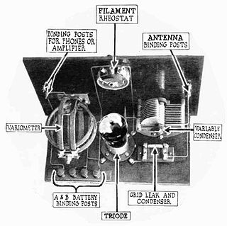
A grid leak detector is an electronic circuit that demodulates an amplitude modulated alternating current and amplifies the recovered modulating voltage. The circuit utilizes the non-linear cathode to control grid conduction characteristic and the amplification factor of a vacuum tube. Invented by Lee De Forest around 1912, it was used as the detector (demodulator) in the first vacuum tube radio receivers until the 1930s.
A direct-conversion receiver (DCR), also known as a homodyne, synchrodyne, zero intermediate frequency or zero-IF receiver, is a radio receiver design that demodulates the incoming radio signal using synchronous detection driven by a local oscillator whose frequency is identical to, or very close to the carrier frequency of the intended signal.

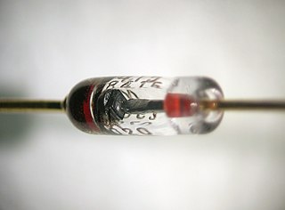
A crystal detector is an obsolete electronic component used in some early 20th century radio receivers that consists of a piece of crystalline mineral which rectifies the alternating current radio signal. It was employed as a detector (demodulator) to extract the audio modulation signal from the modulated carrier, to produce the sound in the earphones. It was the first type of semiconductor diode, and one of the first semiconductor electronic devices. The most common type was the so-called cat's whisker detector, which consisted of a piece of crystalline mineral, usually galena, with a fine wire touching its surface.

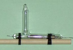
The electrolytic detector, or liquid barretter, was a type of detector (demodulator) used in early radio receivers. First used by Canadian radio researcher Reginald Fessenden in 1903, it was used until about 1913, after which it was superseded by crystal detectors and vacuum tube detectors such as the Fleming valve and Audion (triode). It was considered very sensitive and reliable compared to other detectors available at the time such as the magnetic detector and the coherer. It was one of the first rectifying detectors, able to receive AM (sound) transmissions. On December 24, 1906, US Naval ships with radio receivers equipped with Fessenden's electrolytic detectors received the first AM radio broadcast from Fessenden's Brant Rock, Massachusetts transmitter, consisting of a program of Christmas music.

In radio, a detector is a device or circuit that extracts information from a modulated radio frequency current or voltage. The term dates from the first three decades of radio (1888–1918). Unlike modern radio stations which transmit sound on an uninterrupted carrier wave, early radio stations transmitted information by radiotelegraphy. The transmitter was switched on and off to produce long or short periods of radio waves, spelling out text messages in Morse code. Therefore, early radio receivers could reproduce the Morse code "dots" and "dashes" by simply distinguishing between the presence or absence of a radio signal. The device that performed this function in the receiver circuit was called a detector. A variety of different detector devices, such as the coherer, electrolytic detector, magnetic detector and the crystal detector, were used during the wireless telegraphy era until superseded by vacuum tube technology.

The autodyne circuit was an improvement to radio signal amplification using the De Forest Audion vacuum tube amplifier. By allowing the tube to oscillate at a frequency slightly different from the desired signal, the sensitivity over other receivers was greatly improved. The autodyne circuit was invented by Edwin Howard Armstrong of Columbia University, New York, NY. He inserted a tuned circuit in the output circuit of the Audion vacuum tube amplifier. By adjusting the tuning of this tuned circuit, Armstrong was able to dramatically increase the gain of the Audion amplifier. Further increase in tuning resulted in the Audion amplifier reaching self-oscillation.
Wollaston wire is a very fine platinum wire clad in silver and used in electrical instruments. For most uses, the silver cladding is etched away by acid to expose the platinum core.

The Thing, also known as the Great Seal bug, was one of the first covert listening devices to use passive techniques to transmit an audio signal. It was concealed inside a gift given by the Soviet Union to W. Averell Harriman, the United States Ambassador to the Soviet Union, on August 4, 1945. Because it was passive, needing electromagnetic energy from an outside source to become energized and active, it is considered a predecessor of radio-frequency identification (RFID) technology.

In electronics, a plate detector is a vacuum tube circuit in which an amplifying tube having a control grid is operated in a non-linear region of its grid voltage versus plate current transfer characteristic, usually near plate current cutoff, to demodulate amplitude modulated carrier signal. This differs from the grid leak detector, which utilizes the non-linearity of the grid voltage versus grid current characteristic for demodulation. It also differs from the diode detector, which is a two-terminal device.
