
An amplifier, electronic amplifier or (informally) amp is an electronic device that can increase the magnitude of a signal. It is a two-port electronic circuit that uses electric power from a power supply to increase the amplitude of a signal applied to its input terminals, producing a proportionally greater amplitude signal at its output. The amount of amplification provided by an amplifier is measured by its gain: the ratio of output voltage, current, or power to input. An amplifier is defined as a circuit that has a power gain greater than one.

A microphone, colloquially called a mic, or mike, is a transducer that converts sound into an electrical signal. Microphones are used in many applications such as telephones, hearing aids, public address systems for concert halls and public events, motion picture production, live and recorded audio engineering, sound recording, two-way radios, megaphones, and radio and television broadcasting. They are also used in computers and other electronic devices, such as mobile phones, for recording sounds, speech recognition, VoIP, and other purposes, such as ultrasonic sensors or knock sensors.

Balanced audio is a method of interconnecting audio equipment using balanced interfaces. This type of connection is very important in sound recording and production because it allows the use of long cables while reducing susceptibility to external noise caused by electromagnetic interference. The balanced interface guarantees that induced noise appears as common-mode voltages at the receiver which can be rejected by a differential device.

A balun is an electrical device that allows balanced and unbalanced lines to be interfaced without disturbing the impedance arrangement of either line. A balun can take many forms and may include devices that also transform impedances but need not do so. Sometimes, in the case of transformer baluns, they use magnetic coupling but need not do so. Common-mode chokes are also used as baluns and work by eliminating, rather than rejecting, common mode signals.

In electrical engineering, impedance matching is the practice of designing or adjusting the input impedance or output impedance of an electrical device for a desired value. Often, the desired value is selected to maximize power transfer or minimize signal reflection. For example, impedance matching typically is used to improve power transfer from a radio transmitter via the interconnecting transmission line to the antenna. Signals on a transmission line will be transmitted without reflections if the transmission line is terminated with a matching impedance.
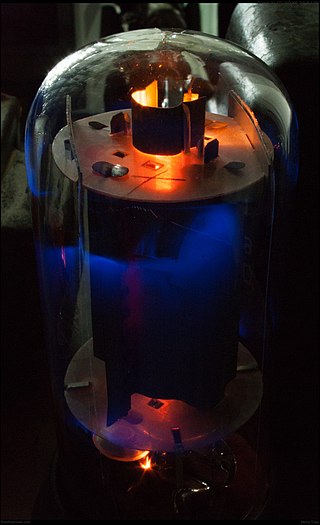
A valve amplifier or tube amplifier is a type of electronic amplifier that uses vacuum tubes to increase the amplitude or power of a signal. Low to medium power valve amplifiers for frequencies below the microwaves were largely replaced by solid state amplifiers in the 1960s and 1970s. Valve amplifiers can be used for applications such as guitar amplifiers, satellite transponders such as DirecTV and GPS, high quality stereo amplifiers, military applications and very high power radio and UHF television transmitters.

A DI unit is an electronic device typically used in recording studios and in sound reinforcement systems to connect a high output impedance unbalanced output signal to a low-impedance, microphone level, balanced input, usually via an XLR connector and XLR cable. DIs are frequently used to connect an electric guitar or electric bass to a mixing console's microphone input jack. Its signal comes "direct" from the source instrument without passing through the air as sound waves, and thus is isolated from other sounds and avoids effects of microphone or room acoustics. The DI performs level matching, balancing, and either active buffering or passive impedance matching/impedance bridging. DI units are typically metal boxes with input and output jacks and, for more expensive units, “ground lift” and attenuator switches.
In electrical engineering, the input impedance of an electrical network is the measure of the opposition to current (impedance), both static (resistance) and dynamic (reactance), into a load network or circuit that is external to the electrical source network. The input admittance is a measure of the load network's propensity to draw current. The source network is the portion of the network that transmits power, and the load network is the portion of the network that consumes power.
In electrical engineering, the output impedance of an electrical network is the measure of the opposition to current flow (impedance), both static (resistance) and dynamic (reactance), into the load network being connected that is internal to the electrical source. The output impedance is a measure of the source's propensity to drop in voltage when the load draws current, the source network being the portion of the network that transmits and the load network being the portion of the network that consumes.
Line level is the specified strength of an audio signal used to transmit analog sound between audio components such as CD and DVD players, television sets, audio amplifiers, and mixing consoles.
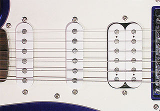
A pickup is an electronic device that converts energy from one form to another that captures or senses mechanical vibrations produced by musical instruments, particularly stringed instruments such as the electric guitar, and converts these to an electrical signal that is amplified using an instrument amplifier to produce musical sounds through a loudspeaker in a speaker enclosure. The signal from a pickup can also be recorded directly.
The cascode is a two-stage amplifier that consists of a common emitter stage feeding into a common base stage when using bipolar junction transistors (BJTs) or alternatively a common source stage feeding a common gate stage when using field-effect transistors (FETs).

An attenuator is a passive broadband electronic device that reduces the power of a signal without appreciably distorting its waveform.
A Wilson current mirror is a three-terminal circuit that accepts an input current at the input terminal and provides a "mirrored" current source or sink output at the output terminal. The mirrored current is a precise copy of the input current.
In electronics, high impedance means that a point in a circuit allows a relatively small amount of current through, per unit of applied voltage at that point. High impedance circuits are low current and potentially high voltage, whereas low impedance circuits are the opposite. Numerical definitions of "high impedance" vary by application.

An L pad is a network composed of two impedances that typically resemble the letter capital "L" when drawn on a schematic circuit diagram. It is commonly used for attenuation and for impedance matching.
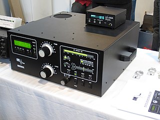
A valve RF amplifier or tube amplifier (U.S.) is a device for electrically amplifying the power of an electrical radio frequency signal.

Various types of electrical transformer are made for different purposes. Despite their design differences, the various types employ the same basic principle as discovered in 1831 by Michael Faraday, and share several key functional parts.
Zobel networks are a type of filter section based on the image-impedance design principle. They are named after Otto Zobel of Bell Labs, who published a much-referenced paper on image filters in 1923. The distinguishing feature of Zobel networks is that the input impedance is fixed in the design independently of the transfer function. This characteristic is achieved at the expense of a much higher component count compared to other types of filter sections. The impedance would normally be specified to be constant and purely resistive. For this reason, Zobel networks are also known as constant resistance networks. However, any impedance achievable with discrete components is possible.
Technical specifications and detailed information on the valve audio amplifier, including its development history.


