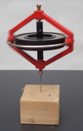
Angular momentum is the rotational analog of linear momentum. It is an important physical quantity because it is a conserved quantity – the total angular momentum of a closed system remains constant. Angular momentum has both a direction and a magnitude, and both are conserved. Bicycles and motorcycles, flying discs, rifled bullets, and gyroscopes owe their useful properties to conservation of angular momentum. Conservation of angular momentum is also why hurricanes form spirals and neutron stars have high rotational rates. In general, conservation limits the possible motion of a system, but it does not uniquely determine it.
A Costas loop is a phase-locked loop (PLL) based circuit which is used for carrier frequency recovery from suppressed-carrier modulation signals and phase modulation signals. It was invented by John P. Costas at General Electric in the 1950s. Its invention was described as having had "a profound effect on modern digital communications". The primary application of Costas loops is in wireless receivers. Its advantage over other PLL-based detectors is that at small deviations the Costas loop error voltage is as compared to . This translates to double the sensitivity and also makes the Costas loop uniquely suited for tracking Doppler-shifted carriers, especially in OFDM and GPS receivers.
Kinematics is a subfield of physics and mathematics, developed in classical mechanics, that describes the motion of points, bodies (objects), and systems of bodies without considering the forces that cause them to move. Kinematics, as a field of study, is often referred to as the "geometry of motion" and is occasionally seen as a branch of both applied and pure mathematics since it can be studied without considering the mass of a body or the forces acting upon it. A kinematics problem begins by describing the geometry of the system and declaring the initial conditions of any known values of position, velocity and/or acceleration of points within the system. Then, using arguments from geometry, the position, velocity and acceleration of any unknown parts of the system can be determined. The study of how forces act on bodies falls within kinetics, not kinematics. For further details, see analytical dynamics.

Flight dynamics is the science of air vehicle orientation and control in three dimensions. The three critical flight dynamics parameters are the angles of rotation in three dimensions about the vehicle's center of gravity (cg), known as pitch, roll and yaw. These are collectively known as aircraft attitude, often principally relative to the atmospheric frame in normal flight, but also relative to terrain during takeoff or landing, or when operating at low elevation. The concept of attitude is not specific to fixed-wing aircraft, but also extends to rotary aircraft such as helicopters, and dirigibles, where the flight dynamics involved in establishing and controlling attitude are entirely different.
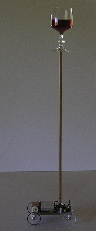
An inverted pendulum is a pendulum that has its center of mass above its pivot point. It is unstable and falls over without additional help. It can be suspended stably in this inverted position by using a control system to monitor the angle of the pole and move the pivot point horizontally back under the center of mass when it starts to fall over, keeping it balanced. The inverted pendulum is a classic problem in dynamics and control theory and is used as a benchmark for testing control strategies. It is often implemented with the pivot point mounted on a cart that can move horizontally under control of an electronic servo system as shown in the photo; this is called a cart and pole apparatus. Most applications limit the pendulum to 1 degree of freedom by affixing the pole to an axis of rotation. Whereas a normal pendulum is stable when hanging downward, an inverted pendulum is inherently unstable, and must be actively balanced in order to remain upright; this can be done either by applying a torque at the pivot point, by moving the pivot point horizontally as part of a feedback system, changing the rate of rotation of a mass mounted on the pendulum on an axis parallel to the pivot axis and thereby generating a net torque on the pendulum, or by oscillating the pivot point vertically. A simple demonstration of moving the pivot point in a feedback system is achieved by balancing an upturned broomstick on the end of one's finger.
In control theory and signal processing, a linear, time-invariant system is said to be minimum-phase if the system and its inverse are causal and stable.
In physics, circular motion is movement of an object along the circumference of a circle or rotation along a circular arc. It can be uniform, with a constant rate of rotation and constant tangential speed, or non-uniform with a changing rate of rotation. The rotation around a fixed axis of a three-dimensional body involves the circular motion of its parts. The equations of motion describe the movement of the center of mass of a body, which remains at a constant distance from the axis of rotation. In circular motion, the distance between the body and a fixed point on its surface remains the same, i.e., the body is assumed rigid.
In physics and astronomy, the Reissner–Nordström metric is a static solution to the Einstein–Maxwell field equations, which corresponds to the gravitational field of a charged, non-rotating, spherically symmetric body of mass M. The analogous solution for a charged, rotating body is given by the Kerr–Newman metric.
A rotating frame of reference is a special case of a non-inertial reference frame that is rotating relative to an inertial reference frame. An everyday example of a rotating reference frame is the surface of the Earth.
In rotordynamics, the rigid rotor is a mechanical model of rotating systems. An arbitrary rigid rotor is a 3-dimensional rigid object, such as a top. To orient such an object in space requires three angles, known as Euler angles. A special rigid rotor is the linear rotor requiring only two angles to describe, for example of a diatomic molecule. More general molecules are 3-dimensional, such as water, ammonia, or methane.

Spacecraft flight dynamics is the application of mechanical dynamics to model how the external forces acting on a space vehicle or spacecraft determine its flight path. These forces are primarily of three types: propulsive force provided by the vehicle's engines; gravitational force exerted by the Earth and other celestial bodies; and aerodynamic lift and drag.

In the mathematical theory of bifurcations, a Hopfbifurcation is a critical point where, as a parameter changes, a system's stability switches and a periodic solution arises. More accurately, it is a local bifurcation in which a fixed point of a dynamical system loses stability, as a pair of complex conjugate eigenvalues—of the linearization around the fixed point—crosses the complex plane imaginary axis as a parameter crosses a threshold value. Under reasonably generic assumptions about the dynamical system, the fixed point becomes a small-amplitude limit cycle as the parameter changes.

In differential geometry, the torsion tensor is a tensor that is associated to any affine connection. The torsion tensor is a bilinear map of two input vectors , that produces an output vector representing the displacement within a tangent space when the tangent space is developed along an infinitesimal parallelogram whose sides are . It is skew symmetric in its inputs, because developing over the parallelogram in the opposite sense produces the opposite displacement, similarly to how a screw moves in opposite ways when it is twisted in two directions.
Hunting oscillation is a self-oscillation, usually unwanted, about an equilibrium. The expression came into use in the 19th century and describes how a system "hunts" for equilibrium. The expression is used to describe phenomena in such diverse fields as electronics, aviation, biology, and railway engineering.
Directional stability is stability of a moving body or vehicle about an axis which is perpendicular to its direction of motion. Stability of a vehicle concerns itself with the tendency of a vehicle to return to its original direction in relation to the oncoming medium when disturbed (rotated) away from that original direction. If a vehicle is directionally stable, a restoring moment is produced which is in a direction opposite to the rotational disturbance. This "pushes" the vehicle so as to return it to the original orientation, thus tending to keep the vehicle oriented in the original direction.

A pendulum is a body suspended from a fixed support such that it freely swings back and forth under the influence of gravity. When a pendulum is displaced sideways from its resting, equilibrium position, it is subject to a restoring force due to gravity that will accelerate it back towards the equilibrium position. When released, the restoring force acting on the pendulum's mass causes it to oscillate about the equilibrium position, swinging it back and forth. The mathematics of pendulums are in general quite complicated. Simplifying assumptions can be made, which in the case of a simple pendulum allow the equations of motion to be solved analytically for small-angle oscillations.

The perifocal coordinate (PQW) system is a frame of reference for an orbit. The frame is centered at the focus of the orbit, i.e. the celestial body about which the orbit is centered. The unit vectors and lie in the plane of the orbit. is directed towards the periapsis of the orbit and has a true anomaly of 90 degrees past the periapsis. The third unit vector is the angular momentum vector and is directed orthogonal to the orbital plane such that:
In geometry, various formalisms exist to express a rotation in three dimensions as a mathematical transformation. In physics, this concept is applied to classical mechanics where rotational kinematics is the science of quantitative description of a purely rotational motion. The orientation of an object at a given instant is described with the same tools, as it is defined as an imaginary rotation from a reference placement in space, rather than an actually observed rotation from a previous placement in space.
The Routh array is a tabular method permitting one to establish the stability of a system using only the coefficients of the characteristic polynomial. Central to the field of control systems design, the Routh–Hurwitz theorem and Routh array emerge by using the Euclidean algorithm and Sturm's theorem in evaluating Cauchy indices.

A yaw rotation is a movement around the yaw axis of a rigid body that changes the direction it is pointing, to the left or right of its direction of motion. The yaw rate or yaw velocity of a car, aircraft, projectile or other rigid body is the angular velocity of this rotation, or rate of change of the heading angle when the aircraft is horizontal. It is commonly measured in degrees per second or radians per second.


