
A pump is a device that moves fluids, or sometimes slurries, by mechanical action, typically converted from electrical energy into hydraulic energy. Pumps can be classified into three major groups according to the method they use to move the fluid: direct lift, displacement, and gravity pumps.
A valve is a device or natural object that regulates, directs or controls the flow of a fluid by opening, closing, or partially obstructing various passageways. Valves are technically fittings, but are usually discussed as a separate category. In an open valve, fluid flows in a direction from higher pressure to lower pressure. The word is derived from the Latin valva, the moving part of a door, in turn from volvere, to turn, roll.
Instrumentation is a collective term for measuring instruments that are used for indicating, measuring and recording physical quantities. The term has its origins in the art and science of scientific instrument-making.
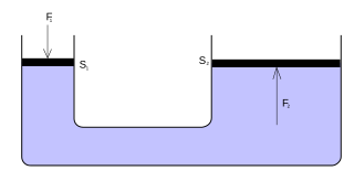
Fluid power is the use of fluids under pressure to generate, control, and transmit power. Fluid power is subdivided into hydraulics using a liquid such as mineral oil or water, and pneumatics using a gas such as air or other gases. Compressed-air and water-pressure systems were once used to transmit power from a central source to industrial users over extended geographic areas; fluid power systems today are usually within a single building or mobile machine.
An industrial process control in continuous production processes is a discipline that uses industrial control systems to achieve a production level of consistency, economy and safety which could not be achieved purely by human manual control. It is implemented widely in industries such as automotive, mining, dredging, oil refining, pulp and paper manufacturing, chemical processing and power generating plants.
A flow control valve regulates the flow or pressure of a fluid. Control valves normally respond to signals generated by independent devices such as flow meters or temperature gauges.

A chemical plant is an industrial process plant that manufactures chemicals, usually on a large scale. The general objective of a chemical plant is to create new material wealth via the chemical or biological transformation and or separation of materials. Chemical plants use specialized equipment, units, and technology in the manufacturing process. Other kinds of plants, such as polymer, pharmaceutical, food, and some beverage production facilities, power plants, oil refineries or other refineries, natural gas processing and biochemical plants, water and wastewater treatment, and pollution control equipment use many technologies that have similarities to chemical plant technology such as fluid systems and chemical reactor systems. Some would consider an oil refinery or a pharmaceutical or polymer manufacturer to be effectively a chemical plant.
A piping and instrumentation diagram (P&ID) is a detailed diagram in the process industry which shows the piping and process equipment together with the instrumentation and control devices.
Building automation is the automatic centralized control of a building's HVAC, electrical, lighting, shading, Access Control, Security Systems, and other interrelated systems through a Building Management System (BMS) or Building Automation System (BAS). The objectives of building automation are improved occupant comfort, efficient operation of building systems, reduction in energy consumption, reduced operating and maintaining costs, increased security, historical performance documentation, remote access/control/operation, and improved life cycle of equipment and related utilities.
Level sensors detect the level of liquids and other fluids and fluidized solids, including slurries, granular materials, and powders that exhibit an upper free surface. Substances that flow become essentially horizontal in their containers because of gravity whereas most bulk solids pile at an angle of repose to a peak. The substance to be measured can be inside a container or can be in its natural form. The level measurement can be either continuous or point values. Continuous level sensors measure level within a specified range and determine the exact amount of substance in a certain place, while point-level sensors only indicate whether the substance is above or below the sensing point. Generally the latter detect levels that are excessively high or low.
In the upstream oil industry, a gas–oil separation plant (GOSP) is temporary or permanent facilities that separate wellhead fluids into constituent vapor (gas) and liquid components.

Vapour-compression refrigeration or vapor-compression refrigeration system (VCRS), in which the refrigerant undergoes phase changes, is one of the many refrigeration cycles and is the most widely used method for air conditioning of buildings and automobiles. It is also used in domestic and commercial refrigerators, large-scale warehouses for chilled or frozen storage of foods and meats, refrigerated trucks and railroad cars, and a host of other commercial and industrial services. Oil refineries, petrochemical and chemical processing plants, and natural gas processing plants are among the many types of industrial plants that often utilize large vapor-compression refrigeration systems. Cascade refrigeration systems may also be implemented using two compressors.
NeSSI is a global and open initiative sponsored by the Center for Process Analysis and Control (CPAC) at the University of Washington, in Seattle.
An oil production plant is a facility which processes production fluids from oil wells in order to separate out key components and prepare them for export. Typical oil well production fluids are a mixture of oil, gas and produced water. An oil production plant is distinct from an oil depot, which does not have processing facilities.
The term separator in oilfield terminology designates a pressure vessel used for separating well fluids produced from oil and gas wells into gaseous and liquid components. A separator for petroleum production is a large vessel designed to separate production fluids into their constituent components of oil, gas and water. A separating vessel may be referred to in the following ways: Oil and gas separator, Separator, Stage separator, Trap, Knockout vessel, Flash chamber, Expansion separator or expansion vessel, Scrubber, Filter. These separating vessels are normally used on a producing lease or platform near the wellhead, manifold, or tank battery to separate fluids produced from oil and gas wells into oil and gas or liquid and gas. An oil and gas separator generally includes the following essential components and features:
A shutdown valve is an actuated valve designed to stop the flow of a hazardous fluid upon the detection of a dangerous event. This provides protection against possible harm to people, equipment or the environment. Shutdown valves form part of a safety instrumented system. The process of providing automated safety protection upon the detection of a hazardous event is called functional safety.

A vapor–liquid separator is a device used in industrial applications to separate a vapor–liquid mixture into its constituent phases. It can be a vertical or horizontal vessel, and can act as a 2-phase or 3-phase separator.
A high-integrity pressure protection system (HIPPS) is a type of safety instrumented system (SIS) designed to prevent over-pressurization of a plant, such as a chemical plant or oil refinery. The HIPPS will shut off the source of the high pressure before the design pressure of the system is exceeded, thus preventing loss of containment through rupture (explosion) of a line or vessel. Therefore, a HIPPS is considered as a barrier between a high-pressure and a low-pressure section of an installation.
Pipeline leak detection is used to determine if and in some cases where a leak has occurred in systems which contain liquids and gases. Methods of detection include hydrostatic testing, infrared, and laser technology after pipeline erection and leak detection during service.
An isolation valve is a valve in a fluid handling system that stops the flow of process media to a given location, usually for maintenance or safety purposes. They can also be used to provide flow logic, and to connect external equipment to a system. A valve is classified as an isolation valve because of its intended function in a system, not because of the type of the valve itself. Therefore, many different types of valves can be classified as isolation valves.


