
Structural engineering is a sub-discipline of civil engineering in which structural engineers are trained to design the 'bones and joints' that create the form and shape of human-made structures. Structural engineers also must understand and calculate the stability, strength, rigidity and earthquake-susceptibility of built structures for buildings and nonbuilding structures. The structural designs are integrated with those of other designers such as architects and building services engineer and often supervise the construction of projects by contractors on site. They can also be involved in the design of machinery, medical equipment, and vehicles where structural integrity affects functioning and safety. See glossary of structural engineering.
In statics and structural mechanics, a structure is statically indeterminate when the static equilibrium equations – force and moment equilibrium conditions – are insufficient for determining the internal forces and reactions on that structure.
An active structure is a mechanical structure with the ability to alter its configuration, form or properties in response to changes in the environment.
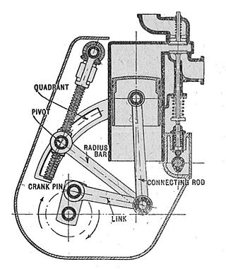
A mechanical linkage is an assembly of systems connected to manage forces and movement. The movement of a body, or link, is studied using geometry so the link is considered to be rigid. The connections between links are modeled as providing ideal movement, pure rotation or sliding for example, and are called joints. A linkage modeled as a network of rigid links and ideal joints is called a kinematic chain.
Seismic analysis is a subset of structural analysis and is the calculation of the response of a building structure to earthquakes. It is part of the process of structural design, earthquake engineering or structural assessment and retrofit in regions where earthquakes are prevalent.
Earthquake engineering is an interdisciplinary branch of engineering that designs and analyzes structures, such as buildings and bridges, with earthquakes in mind. Its overall goal is to make such structures more resistant to earthquakes. An earthquake engineer aims to construct structures that will not be damaged in minor shaking and will avoid serious damage or collapse in a major earthquake. A properly engineered structure does not necessarily have to be extremely strong or expensive. It has to be properly designed to withstand the seismic effects while sustaining an acceptable level of damage.
In structural engineering, the flexibility method, also called the method of consistent deformations, is the traditional method for computing member forces and displacements in structural systems. Its modern version formulated in terms of the members' flexibility matrices also has the name the matrix force method due to its use of member forces as the primary unknowns.
As one of the methods of structural analysis, the direct stiffness method, also known as the matrix stiffness method, is particularly suited for computer-automated analysis of complex structures including the statically indeterminate type. It is a matrix method that makes use of the members' stiffness relations for computing member forces and displacements in structures. The direct stiffness method is the most common implementation of the finite element method (FEM). In applying the method, the system must be modeled as a set of simpler, idealized elements interconnected at the nodes. The material stiffness properties of these elements are then, through matrix mathematics, compiled into a single matrix equation which governs the behaviour of the entire idealized structure. The structure’s unknown displacements and forces can then be determined by solving this equation. The direct stiffness method forms the basis for most commercial and free source finite element software.

A mirror mount is a device that holds a mirror. In optics research, these can be quite sophisticated devices, due to the need to be able to tip and tilt the mirror by controlled amounts, while still holding it in a precise position when it is not being adjusted.
The finite element method (FEM) is a powerful technique originally developed for numerical solution of complex problems in structural mechanics, and it remains the method of choice for complex systems. In the FEM, the structural system is modeled by a set of appropriate finite elements interconnected at discrete points called nodes. Elements may have physical properties such as thickness, coefficient of thermal expansion, density, Young's modulus, shear modulus and Poisson's ratio.
Applied mechanics is the branch of science concerned with the motion of any substance that can be experienced or perceived by humans without the help of instruments. In short, when mechanics concepts surpass being theoretical and are applied and executed, general mechanics becomes applied mechanics. It is this stark difference that makes applied mechanics an essential understanding for practical everyday life. It has numerous applications in a wide variety of fields and disciplines, including but not limited to structural engineering, astronomy, oceanography, meteorology, hydraulics, mechanical engineering, aerospace engineering, nanotechnology, structural design, earthquake engineering, fluid dynamics, planetary sciences, and other life sciences. Connecting research between numerous disciplines, applied mechanics plays an important role in both science and engineering.

In the structural engineering beam theory, the term "plastic hinge" is used to describe the deformation of a section of a beam where plastic bending occurs. In earthquake engineering plastic hinge is also a type of energy damping device allowing plastic rotation [deformation] of an otherwise rigid column connection.
Kinematic coupling describes fixtures designed to exactly constrain the part in question, providing precision and certainty of location. A canonical example of a kinematic coupling consists of three radial v-grooves in one part that mate with three hemispheres in another part. Each hemisphere has two contact points for a total of six contact points, enough to constrain all six of the part's degrees of freedom. An alternative design consists of three hemispheres on one part that fit respectively into a tetrahedral dent, a v-groove, and a flat.
Structural dynamics is a type of structural analysis which covers the behavior of a structure subjected to dynamic loading. Dynamic loads include people, wind, waves, traffic, earthquakes, and blasts. Any structure can be subjected to dynamic loading. Dynamic analysis can be used to find dynamic displacements, time history, and modal analysis.

Anchor bolts are used to connect structural and non-structural elements to concrete. The connection can be made by a variety of different components: anchor bolts, steel plates, or stiffeners. Anchor bolts transfer different types of load: tension forces and shear forces.
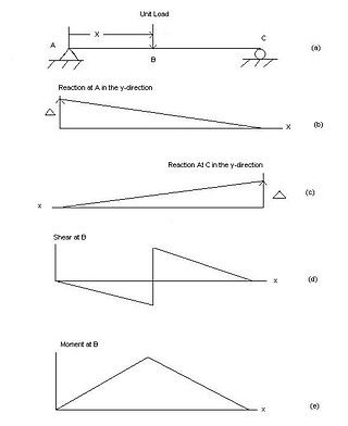
In engineering, an influence line graphs the variation of a function at a specific point on a beam or truss caused by a unit load placed at any point along the structure. Common functions studied with influence lines include reactions, shear, moment, and deflection (Deformation). Influence lines are important in designing beams and trusses used in bridges, crane rails, conveyor belts, floor girders, and other structures where loads will move along their span. The influence lines show where a load will create the maximum effect for any of the functions studied.

Precision engineering is a subdiscipline of electrical engineering, software engineering, electronics engineering, mechanical engineering, and optical engineering concerned with designing machines, fixtures, and other structures that have exceptionally low tolerances, are repeatable, and are stable over time. These approaches have applications in machine tools, MEMS, NEMS, optoelectronics design, and many other fields.
Slope stability analysis is a static or dynamic, analytical or empirical method to evaluate the stability of slopes of soil- and rock-fill dams, embankments, excavated slopes, and natural slopes in soil and rock. It is performed to assess the safe design of a human-made or natural slopes and the equilibrium conditions. Slope stability is the resistance of inclined surface to failure by sliding or collapsing. The main objectives of slope stability analysis are finding endangered areas, investigation of potential failure mechanisms, determination of the slope sensitivity to different triggering mechanisms, designing of optimal slopes with regard to safety, reliability and economics, designing possible remedial measures, e.g. barriers and stabilization.

Discontinuity layout optimization (DLO) is an engineering analysis procedure which can be used to directly establish the amount of load that can be carried by a solid or structure prior to collapse. Using DLO the layout of failure planes, or 'discontinuities', in a collapsing solid or structure are identified using mathematical optimization methods. It is assumed that failure occurs in a ductile or 'plastic' manner.
A quick return mechanism is an apparatus to produce a reciprocating motion in which the time taken for travel in return stroke is less than in the forward stroke. It is driven by a circular motion source and uses a system of links with three turning pairs and a sliding pair. A quick-return mechanism is a subclass of a slider-crank linkage, with an offset crank.