Kinematic synthesis

Last updated

In mechanical engineering, kinematic synthesis (also known as mechanism synthesis) determines the size and configuration of mechanisms that shape the flow of power through a mechanical system, or machine, to achieve a desired performance. [1] The word synthesis refers to combining parts to form a whole. [2] Hartenberg and Denavit describe kinematic synthesis as [3]

Contents

...it is design, the creation of something new. Kinematically, it is the conversion of a motion idea into hardware.

The earliest machines were designed to amplify human and animal effort, later gear trains and linkage systems captured wind and flowing water to rotate millstones and pumps. Now machines use chemical and electric power to manufacture, transport, and process items of all types. And kinematic synthesis is the collection of techniques for designing those elements of these machines that achieve required output forces and movement for a given input.

Applications of kinematic synthesis include determining:

Kinematic synthesis for a mechanical system is described as having three general phases, known as type synthesis, number synthesis and dimensional synthesis. [3] Type synthesis matches the general characteristics of a mechanical system to the task at hand, selecting from an array of devices such as a cam-follower mechanism, linkage, gear train, a fixture or a robotic system for use in a required task. Number synthesis considers the various ways a particular device can be constructed, generally focussed on the number and features of the parts. Finally, dimensional synthesis determines the geometry and assembly of the components that form the device.

Linkage synthesis

A linkage is an assembly of links and joints that is designed to provide required force and movement. Number synthesis of linkages which considers the number of links and the configuration of the joints is often called type synthesis, because it identifies the type of linkage. [10] Generally, the number of bars, the joint types, and the configuration of the links and joints are determined before starting dimensional synthesis. [11] However, design strategies have been developed that combine type and dimensional synthesis. [12]

Dimensional synthesis of linkages begins with a task defined as the movement of an output link relative to a base reference frame. This task may consist of the trajectory of a moving point or the trajectory of a moving body. The kinematics equations, or loop equations, of the mechanism must be satisfied in all of the required positions of the moving point or body. The result is a system of equations that are solved to compute the dimensions of the linkage. [4]

There are three general tasks for dimensional synthesis, i) path generation, in which the trajectory of a point in the output link is required, ii) motion generation, in which the trajectory of the output link is required, and iii) function generation in which the movement of the output link relative to an input link is required. [3] The equations for function generation can be obtained from those for motion generation by considering the movement of the output link relative to an input link, rather than relative to the base frame.

The trajectory and motion requirements for dimensional synthesis are defined as sets of either instantaneous positions or finite positions. Instantaneous positions is a convenient way to describe requirements on the differential properties of the trajectory of a point or body, which are geometric versions of velocity, acceleration and rate of change of acceleration. The mathematical results that support instantaneous position synthesis are called curvature theory. [13]

Finite-position synthesis has a task defined as a set of positions of the moving body relative to a base frame, or relative to an input link. A crank that connects a moving pivot to a base pivot constrains the center of the moving pivot to follow a circle. This yields constraint equations that can be solved graphically using techniques developed by L. Burmester, [14] and called Burmester theory.

Cam and follower design

A cam and follower mechanism uses the shape of the cam to guide the movement of the follower by direct contact. Kinematic synthesis of a cam and follower mechanism consists of finding the shape of the cam that guides a particular follower through the required movement. [15]

Examples of cams with a knife edge, a roller and a flat-faced follower Came disque types suiveurs.svg
Examples of cams with a knife edge, a roller and a flat-faced follower

A plate cam is connected to a base frame by hinged joint and the contour of the cam forms a surface that pushes on a follower. The connection of the follower to the base frame can be either a hinged or sliding joint to form a rotating and translating follower. The portion of the follower that contacts the cam can have any shape, such as a knife-edge, a roller, or flat-faced contact. As the cam rotates its contact with the follower face drives its output rotation or sliding movement.

The task for a cam and follower mechanism is provided by a displacement diagram, which defines the rotation angle or sliding distance of the follower as a function of the rotation of the cam. Once the contact shape of follower and its motion are defined, the cam can be constructed using graphical or numerical techniques. [15]

Gear teeth and gear train design

A pair of mating gears can be viewed as a cam and follower mechanism designed to use the rotary movement of an input shaft to drive the rotary movement of an output shaft. [15] This is achieved by providing a series of cam and followers, or gear teeth, distributed around the circumferences of two circles that form the mating gears. Early implementation of this rotary movement used cylindrical and rectangular teeth without concern for smooth transmission of movement, while the teeth were engaged---see the photo of the main drive gears for the windmill Doesburgermolen in Ede, Netherlands.

Windmill drive gears of the Doesburgermolen in Ede, Netherlands. Doesburger molen Ede aandrijfwerk 2e maalstoel.jpg
Windmill drive gears of the Doesburgermolen in Ede, Netherlands.

The geometric requirement that ensures smooth movement of contacting gear teeth is known as the fundamental law of gearing. This law states that for two bodies rotating about separate centers and in contact along their profiles, the relative angular velocity of the two will be constant as long as the line perpendicular to the point of contact of their two profiles, the profile normal, passes through the same point along the line between their centers throughout their movement. [15] A pair of tooth profiles that satisfy the fundamental law of gearing are said to be conjugate to each other. The involute profile that is used for most gear teeth today is self-conjugate, which means that if the teeth of two gears are the same size then they will mesh smoothly independent of the diameters of the mating gears.

The relative movement of gears with conjugate tooth profiles is defined by the distance from the center of each gear to the point at which the profile normal intersects the line of centers. This is known as the radius of the pitch circle for each gear. The calculation of the speed ratios for a gear train with conjugate gear teeth becomes a calculation using the ratios of the radii of the pitch circles that make up the gear train. [15]

Gear train design uses the desired speed ratio for a system of gears to select the number of gears, their configuration, and the size of their pitch circles. This is independent of the selection of the gear teeth as long as the tooth profiles are conjugate, with the exception that the circumferences of the pitch circles must provide for a whole number of teeth.

Related Research Articles

<span class="mw-page-title-main">Analog computer</span> Computer that uses continuously varying data technology

An analog computer or analogue computer is a type of computer that uses the continuous variation aspect of physical phenomena such as electrical, mechanical, or hydraulic quantities to model the problem being solved. In contrast, digital computers represent varying quantities symbolically and by discrete values of both time and amplitude.

<span class="mw-page-title-main">Simple machine</span> Mechanical device that changes the direction or magnitude of a force

A simple machine is a mechanical device that changes the direction or magnitude of a force. In general, they can be defined as the simplest mechanisms that use mechanical advantage to multiply force. Usually the term refers to the six classical simple machines that were defined by Renaissance scientists:

<span class="mw-page-title-main">Cam (mechanism)</span> Rotating or sliding component that transmits variable motion to a follower

A cam is a rotating or sliding piece in a mechanical linkage used especially in transforming rotary motion into linear motion. It is often a part of a rotating wheel or shaft that strikes a lever at one or more points on its circular path. The cam can be a simple tooth, as is used to deliver pulses of power to a steam hammer, for example, or an eccentric disc or other shape that produces a smooth reciprocating motion in the follower, which is a lever making contact with the cam. A cam timer is similar, and were widely used for electric machine control before the advent of inexpensive electronics, microcontrollers, integrated circuits, programmable logic controllers and digital control.

<span class="mw-page-title-main">Machine</span> Powered mechanical device

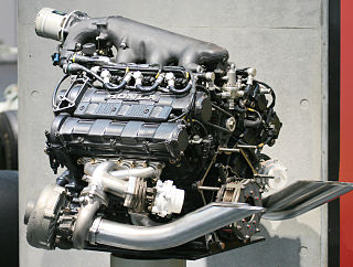
A machine is a physical system that uses power to apply forces and control movement to perform an action. The term is commonly applied to artificial devices, such as those employing engines or motors, but also to natural biological macromolecules, such as molecular machines. Machines can be driven by animals and people, by natural forces such as wind and water, and by chemical, thermal, or electrical power, and include a system of mechanisms that shape the actuator input to achieve a specific application of output forces and movement. They can also include computers and sensors that monitor performance and plan movement, often called mechanical systems.

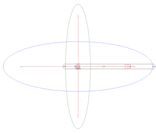
Kinematics is a subfield of physics, developed in classical mechanics, that describes the motion of points, bodies (objects), and systems of bodies without considering the forces that cause them to move. Kinematics, as a field of study, is often referred to as the "geometry of motion" and is occasionally seen as a branch of mathematics. A kinematics problem begins by describing the geometry of the system and declaring the initial conditions of any known values of position, velocity and/or acceleration of points within the system. Then, using arguments from geometry, the position, velocity and acceleration of any unknown parts of the system can be determined. The study of how forces act on bodies falls within kinetics, not kinematics. For further details, see analytical dynamics.

<span class="mw-page-title-main">Epicyclic gearing</span> Two gears mounted so the center of one gear revolves around the center of the other

An epicyclic gear train is a gear reduction assembly consisting of two gears mounted so that the center of one gear revolves around the center of the other. A carrier connects the centers of the two gears and rotates, to carry the planet gear(s) around the sun gear. The planet and sun gears mesh so that their pitch circles roll without slip. If the sun gear is held fixed, then a point on the pitch circle of the planet gear traces an epicycloid curve.

<span class="mw-page-title-main">Inverse kinematics</span> Computing joint values of a kinematic chain from a known end position

In computer animation and robotics, inverse kinematics is the mathematical process of calculating the variable joint parameters needed to place the end of a kinematic chain, such as a robot manipulator or animation character's skeleton, in a given position and orientation relative to the start of the chain. Given joint parameters, the position and orientation of the chain's end, e.g. the hand of the character or robot, can typically be calculated directly using multiple applications of trigonometric formulas, a process known as forward kinematics. However, the reverse operation is, in general, much more challenging.

<span class="mw-page-title-main">Robot kinematics</span> Geometric analysis of multi-DoF kinematic chains that model a robot

In robotics, robot kinematics applies geometry to the study of the movement of multi-degree of freedom kinematic chains that form the structure of robotic systems. The emphasis on geometry means that the links of the robot are modeled as rigid bodies and its joints are assumed to provide pure rotation or translation.

<span class="mw-page-title-main">Four-bar linkage</span> Mechanical linkage consisting of four links connected by joints in a loop

In the study of mechanisms, a four-bar linkage, also called a four-bar, is the simplest closed-chain movable linkage. It consists of four bodies, called bars or links, connected in a loop by four joints. Generally, the joints are configured so the links move in parallel planes, and the assembly is called a planar four-bar linkage. Spherical and spatial four-bar linkages also exist and are used in practice.

<span class="mw-page-title-main">Linkage (mechanical)</span> Assembly of systems connected to manage forces and movement

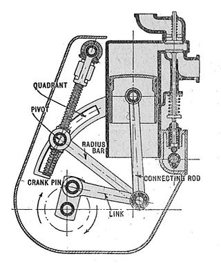
A mechanical linkage is an assembly of systems connected to manage forces and movement. The movement of a body, or link, is studied using geometry so the link is considered to be rigid. The connections between links are modeled as providing ideal movement, pure rotation or sliding for example, and are called joints. A linkage modeled as a network of rigid links and ideal joints is called a kinematic chain.

<span class="mw-page-title-main">Gear train</span> Mechanical transmission using multiple gears

A gear train or gear set is a machine element of a mechanical system formed by mounting two or more gears on a frame such that the teeth of the gears engage.

In physics, the degrees of freedom (DOF) of a mechanical system is the number of independent parameters that define its configuration or state. It is important in the analysis of systems of bodies in mechanical engineering, structural engineering, aerospace engineering, robotics, and other fields.

<span class="mw-page-title-main">Overconstrained mechanism</span> Moveable linkage with zero mobility

In mechanical engineering, an overconstrained mechanism is a linkage that has more degrees of freedom than is predicted by the mobility formula. The mobility formula evaluates the degree of freedom of a system of rigid bodies that results when constraints are imposed in the form of joints between the links.

The following outline is provided as an overview of and topical guide to machines:

In classical mechanics, a kinematic pair is a connection between two physical objects that imposes constraints on their relative movement (kinematics). German engineer Franz Reuleaux introduced the kinematic pair as a new approach to the study of machines that provided an advance over the motion of elements consisting of simple machines.

<span class="mw-page-title-main">Kinematic chain</span> Mathematical model for a mechanical system

In mechanical engineering, a kinematic chain is an assembly of rigid bodies connected by joints to provide constrained motion that is the mathematical model for a mechanical system. As the word chain suggests, the rigid bodies, or links, are constrained by their connections to other links. An example is the simple open chain formed by links connected in series, like the usual chain, which is the kinematic model for a typical robot manipulator.

<span class="mw-page-title-main">Mechanism (engineering)</span> Device used to transfer forces via non-electric means

In engineering, a mechanism is a device that transforms input forces and movement into a desired set of output forces and movement. Mechanisms generally consist of moving components which may include:

In kinematics, Burmester theory comprises geometric techniques for synthesis of linkages. It was introduced in the late 19th century by Ludwig Burmester (1840–1927). His approach was to compute the geometric constraints of the linkage directly from the inventor's desired movement for a floating link. From this point of view a four-bar linkage is a floating link that has two points constrained to lie on two circles.

Kinematics equations are the constraint equations of a mechanical system such as a robot manipulator that define how input movement at one or more joints specifies the configuration of the device, in order to achieve a task position or end-effector location. Kinematics equations are used to analyze and design articulated systems ranging from four-bar linkages to serial and parallel robots.

<span class="mw-page-title-main">Five-bar linkage</span> 2-DoF mechanism with 5 links and 5 joints

In kinematics, a five-bar linkage is a mechanism with two degrees of freedom that is constructed from five links that are connected together in a closed chain. All links are connected to each other by five joints in series forming a loop. One of the links is the ground or base. This configuration is also called a pantograph, however, it is not to be confused with the parallelogram-copying linkage pantograph.

References

  1. J. M. McCarthy and Leo Joskowitz, Ch. 9 Kinematic Synthesis, Formal Engineering Design Synthesis, (J. Cagan and E. Antonson, eds.), Cambridge Univ. Press 2002.
  2. Merriam-Webster dictionary, synthesis
  3. 1 2 3 Hartenberg, R.S. and J. Denavit (1964) Kinematic synthesis of linkages, New York: McGraw-Hill — Online link from Cornell University.
  4. 1 2 J. M. McCarthy and G. S. Soh, Geometric Design of Linkages, 2nd Edition, Springer 2010, dos 10.1007/978-1-4419-7892-9
  5. J. J. Craig, Introduction to Robotics: Mechanics and Control, 4th Edition, Pearson Publishing, 2018
  6. M. T. Mason and J. K. Salisbury, Robot Hands and the Mechanics of Manipulation, MIT Press, 1985
  7. M.A. González-Palacios and J. Angeles, Cam Synthesis, Springer Netherlands, 1993, 10.1007/978-94-011-1890-3
  8. D. Dooner, Kinematic Geometry of Gearing, Wiley Publishing, 2012, ISBN   978-1-119-95094-3
  9. A. Slocum, Kinematic Couplings: A Review of Design Principles and Applications International Journal of Machine Tools and Manufacture 50.4 (2010): 310-327.
  10. J. M. McCarthy, Type synthesis: Gruebler's equation, Assur groups, Baranov trusses, Graph theory, and Rigidity, MDA Press, 2017
  11. L. W. Tsai, Mechanism Design: Enumeration of Kinematic Structures According to Function, CRC Press, 2000
  12. X. Li, P. Zhao, Q. J. Ge, and A. Purwar, A Task Driven Approach to Simultaneous Type Synthesis and Dimensional Optimization of Planar Parallel Manipulator Using Algebraic Fitting of a Family of Quadrics, ASME 2013 International Design Engineering Technical Conferences and Computers and Information in Engineering Conference, Volume 6B: 37th Mechanisms and Robotics Conference Portland, Oregon, USA, August 4–7, 2013
  13. G. R. Veldkamp, Curvature Theory in Plane Kinematics Doctor of Philosophy, Delft University of Technology, 1963
  14. L. Burmester, Lehrbuch der Kinematik, Felix Verlag, Leipzig, 1888
  15. 1 2 3 4 5 J. J. Uicker, G. R. Pennock, and J. E. Shigley, Theory of Machines and Mechanisms, Fifth Ed., Oxford University Press, 2016.