Lift-induced drag

Last updated

Lift-induced drag, induced drag, vortex drag, or sometimes drag due to lift, in aerodynamics, is an aerodynamic drag force that occurs whenever a moving object redirects the airflow coming at it. This drag force occurs in airplanes due to wings or a lifting body redirecting air to cause lift and also in cars with airfoil wings that redirect air to cause a downforce. It is symbolized as , and the lift-induced drag coefficient as .

Contents

For a constant amount of lift, induced drag can be reduced by increasing airspeed. A counter-intuitive effect of this is that, up to the speed-for-minimum-drag, aircraft need less power to fly faster. [1] Induced drag is also reduced when the wingspan is higher, [2] or for wings with wingtip devices.

Explanation

Induced drag is related to the angle of the induced downwash in the vicinity of the wing. The grey vertical line labeled "L" is the force required to counteract the weight of the aircraft. The red vector labeled "Leff" is the actual lift on the wing; it is perpendicular to the effective relative airflow in the vicinity of the wing. The lift generated by the wing has been tilted rearwards through an angle equal to the downwash angle in three-dimensional flow. The component of "Leff" parallel to the free stream is the induced drag on the wing. Induce drag downwash.png
Induced drag is related to the angle of the induced downwash in the vicinity of the wing. The grey vertical line labeled "L" is the force required to counteract the weight of the aircraft. The red vector labeled "Leff" is the actual lift on the wing; it is perpendicular to the effective relative airflow in the vicinity of the wing. The lift generated by the wing has been tilted rearwards through an angle equal to the downwash angle in three-dimensional flow. The component of "Leff" parallel to the free stream is the induced drag on the wing.

The total aerodynamic force acting on a body is usually thought of as having two components, lift and drag. By definition, the component of force parallel to the oncoming flow is called drag; and the component perpendicular to the oncoming flow is called lift. [7] [4] :Section 5.3 At practical angles of attack the lift greatly exceeds the drag. [8]

Lift is produced by the changing direction of the flow around a wing. The change of direction results in a change of velocity (even if there is no speed change), which is an acceleration. To change the direction of the flow therefore requires that a force be applied to the fluid; the total aerodynamic force is simply the reaction force of the fluid acting on the wing.

An aircraft in slow flight at a high angle of attack will generate an aerodynamic reaction force with a high drag component. By increasing the speed and reducing the angle of attack, the lift generated can be held constant while the drag component is reduced. At the optimum angle of attack, total drag is minimised. If speed is increased beyond this, total drag will increase again due to increased profile drag.

Vortices

When producing lift, air below the wing is at a higher pressure than the air pressure above the wing. On a wing of finite span, this pressure difference causes air to flow from the lower surface, around the wingtip, towards the upper surface. [9] :8.1.1 This spanwise flow of air combines with chordwise flowing air, which twists the airflow and produces vortices along the wing trailing edge. Induced drag is the cause of the vortices; the vortices do not cause induced drag. [6] :4.6 [6] :4.7 [9] :8.1.4,8.3,8.4.1

The vortices reduce the wing's ability to generate lift, so that it requires a higher angle of attack for the same lift, which tilts the total aerodynamic force rearwards and increases the drag component of that force. The angular deflection is small and has little effect on the lift. However, there is an increase in the drag equal to the product of the lift force and the angle through which it is deflected. Since the deflection is itself a function of the lift, the additional drag is proportional to the square of the lift. [4] :Section 5.17

The vortices created are unstable,[ clarification needed ] and they quickly combine to produce wingtip vortices which trail behind the wingtip. [4] :Section 5.14

Calculation of induced drag

For a planar wing with an elliptical lift distribution, induced drag Di can be calculated as follows:

,

where

is the lift,
is the standard density of air at sea level,
is the equivalent airspeed,
is the ratio of circumference to diameter of a circle, and
is the wingspan.

From this equation it is clear that the induced drag varies with the square of the lift; and inversely with the square of the equivalent airspeed; and inversely with the square of the wingspan. Deviation from the non-planar wing with elliptical lift distribution are taken into account by dividing the induced drag by the span efficiency factor .

To compare with other sources of drag, it can be convenient to express this equation in terms of lift and drag coefficients: [10]

, where

and

is the aspect ratio,
is a reference wing area.

This indicates how, for a given wing area, high aspect ratio wings are beneficial to flight efficiency. With being a function of angle of attack, induced drag increases as the angle of attack increases. [4] :Section 5.17

The above equation can be derived using Prandtl's lifting-line theory.[ citation needed ] Similar methods can also be used to compute the minimum induced drag for non-planar wings or for arbitrary lift distributions.[ citation needed ]

Reducing induced drag

According to the equations above, for wings generating the same lift, the induced drag is inversely proportional to the square of the wingspan. A wing of infinite span and uniform airfoil segment (or a 2D wing) would experience no induced drag. [11] The drag characteristics of a wing with infinite span can be simulated using an airfoil segment the width of a wind tunnel. [12]

An increase in wingspan or a solution with a similar effect is one way to reduce induced drag. [6] :4.10 The Wright brothers used curved trailing edges on their rectangular wings. [13] Some early aircraft had fins mounted on the tips. More recent aircraft have wingtip-mounted winglets to reduce the induced drag. [14] Winglets also provide some benefit by increasing the vertical height of the wing system. [6] :4.10 Wingtip mounted fuel tanks and wing washout may also provide some benefit.[ citation needed ]

Typically, the elliptical spanwise distribution of lift produces the minimum induced drag [15] for a planar wing of a given span. A small number of aircraft have a planform approaching the elliptical — the most famous examples being the World War II Spitfire [13] and Thunderbolt. For modern wings with winglets, the ideal lift distribution is not elliptical. [6] :4.9

For a given wing area, a high aspect ratio wing will produce less induced drag than a wing of low aspect ratio. [16] While induced drag is inversely proportional to the square of the wingspan, not necessarily inversely proportional to aspect ratio, if the wing area is held constant, then induced drag will be inversely proportional to aspect ratio. However, since wingspan can be increased while decreasing aspect ratio, or vice versa, the apparent relationship between aspect ratio and induced drag does not always hold. [2] [9] :489

For a typical twin-engine wide-body aircraft at cruise speed, induced drag is the second-largest component of total drag, accounting for approximately 37% of total drag. Skin friction drag is the largest component of total drag, at almost 48%. [17] [18] [19] :20 Reducing induced drag can therefore significantly reduce cost and environmental impact. [19] :18

Combined effect with other drag sources

Total drag is parasitic drag plus induced drag Drag curves for aircraft in flight.svg
Total drag is parasitic drag plus induced drag

In 1891, Samuel Langley published the results of his experiments on various flat plates. At the same airspeed and the same angle of attack, plates with higher aspect ratio produced greater lift and experienced lower drag than those with lower aspect ratio. [1]

His experiments were carried out at relatively low airspeeds, slower than the speed for minimum drag. [20] He observed that, at these low airspeeds, increasing speed required reducing power. [21] (At higher airspeeds, parasitic drag came to dominate, causing the power required to increase with increasing airspeed.)

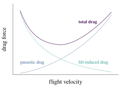
Induced drag must be added to the parasitic drag to find the total drag. Since induced drag is inversely proportional to the square of the airspeed (at a given lift) whereas parasitic drag is proportional to the square of the airspeed, the combined overall drag curve shows a minimum at some airspeed - the minimum drag speed (VMD). An aircraft flying at this speed is operating at its optimal aerodynamic efficiency. According to the above equations, the speed for minimum drag occurs at the speed where the induced drag is equal to the parasitic drag. [4] :Section 5.25 This is the speed at which for unpowered aircraft, optimum glide angle is achieved. This is also the speed for greatest range (although VMD will decrease as the plane consumes fuel and becomes lighter). The speed for greatest range (i.e. distance travelled) is the speed at which a straight line from the origin is tangent to the fuel flow rate curve.

The curve of range versus airspeed is normally very shallow and it is customary to operate at the speed for 99% best range since this gives 3-5% greater speed for only 1% less range. Flying higher where the air is thinner will raise the speed at which minimum drag occurs, and so permits a faster voyage for the same amount of fuel. If the plane is flying at the maximum permissible speed, then there is an altitude at which the air density will be sufficient to keep it aloft while flying at the angle of attack that minimizes the drag. The optimum altitude will increase during the flight as the plane becomes lighter.

The speed for maximum endurance (i.e. time in the air) is the speed for minimum fuel flow rate, and is always less than the speed for greatest range. The fuel flow rate is calculated as the product of the power required and the engine specific fuel consumption (fuel flow rate per unit of power [lower-alpha 1] ). The power required is equal to the drag times the speed.

See also

Notes

  1. The engine specific fuel consumption is normally expressed in units of fuel flow rate per unit of thrust or per unit of power depending on whether the engine output is measured in thrust, as for a jet engine, or shaft horsepower, as for a propeller engine. To convert fuel rate per unit thrust to fuel rate per unit power one must divide by the speed.

Related Research Articles

<span class="mw-page-title-main">Lift (force)</span> Force perpendicular to flow of surrounding fluid

When a fluid flows around an object, the fluid exerts a force on the object. Lift is the component of this force that is perpendicular to the oncoming flow direction. It contrasts with the drag force, which is the component of the force parallel to the flow direction. Lift conventionally acts in an upward direction in order to counter the force of gravity, but it is defined to act perpendicular to the flow and therefore can act in any direction.

<span class="mw-page-title-main">Wing</span> Appendage used for flight

A wing is a type of fin that produces lift while moving through air or some other fluid. Accordingly, wings have streamlined cross-sections that are subject to aerodynamic forces and act as airfoils. A wing's aerodynamic efficiency is expressed as its lift-to-drag ratio. The lift a wing generates at a given speed and angle of attack can be one to two orders of magnitude greater than the total drag on the wing. A high lift-to-drag ratio requires a significantly smaller thrust to propel the wings through the air at sufficient lift.

<span class="mw-page-title-main">Chord (aeronautics)</span> Imaginary straight line joining the leading and trailing edges of an aerofoil

In aeronautics, the chord is an imaginary straight line joining the leading edge and trailing edge of an aerofoil. The chord length is the distance between the trailing edge and the point where the chord intersects the leading edge. The point on the leading edge used to define the chord may be the surface point of minimum radius. For a turbine aerofoil the chord may be defined by the line between points where the front and rear of a 2-dimensional blade section would touch a flat surface when laid convex-side up.

<span class="mw-page-title-main">Aspect ratio (aeronautics)</span> Ratio of an aircrafts wing span to its mean chord

In aeronautics, the aspect ratio of a wing is the ratio of its span to its mean chord. It is equal to the square of the wingspan divided by the wing area. Thus, a long, narrow wing has a high aspect ratio, whereas a short, wide wing has a low aspect ratio.

<span class="mw-page-title-main">Airfoil</span> Cross-sectional shape of a wing, blade of a propeller, rotor, or turbine, or sail

An airfoil or aerofoil is a streamlined body that is capable of generating significantly more lift than drag. Wings, sails and propeller blades are examples of airfoils. Foils of similar function designed with water as the working fluid are called hydrofoils.

<span class="mw-page-title-main">Lift-to-drag ratio</span> Measure of aerodynamic efficiency

In aerodynamics, the lift-to-drag ratio is the lift generated by an aerodynamic body such as an aerofoil or aircraft, divided by the aerodynamic drag caused by moving through air. It describes the aerodynamic efficiency under given flight conditions. The L/D ratio for any given body will vary according to these flight conditions.

In fluid dynamics, the lift coefficient is a dimensionless quantity that relates the lift generated by a lifting body to the fluid density around the body, the fluid velocity and an associated reference area. A lifting body is a foil or a complete foil-bearing body such as a fixed-wing aircraft. CL is a function of the angle of the body to the flow, its Reynolds number and its Mach number. The section lift coefficient cl refers to the dynamic lift characteristics of a two-dimensional foil section, with the reference area replaced by the foil chord.

<span class="mw-page-title-main">Wingtip device</span> Aircraft component fixed to the end of the wings to improve performance

Wingtip devices are intended to improve the efficiency of fixed-wing aircraft by reducing drag. Although there are several types of wing tip devices which function in different manners, their intended effect is always to reduce an aircraft's drag. Wingtip devices can also improve aircraft handling characteristics and enhance safety for following aircraft. Such devices increase the effective aspect ratio of a wing without greatly increasing the wingspan. Extending the span would lower lift-induced drag, but would increase parasitic drag and would require boosting the strength and weight of the wing. At some point, there is no net benefit from further increased span. There may also be operational considerations that limit the allowable wingspan.

<span class="mw-page-title-main">Parasitic drag</span> Aerodynamic resistance against the motion of an object

Parasitic drag, also known as profile drag, is a type of aerodynamic drag that acts on any object when the object is moving through a fluid. Parasitic drag is a combination of form drag and skin friction drag. It affects all objects regardless of whether they are capable of generating lift.

<span class="mw-page-title-main">Downforce</span> Downwards lift force created by the aerodynamic characteristics of a vehicle

Downforce is a downwards lift force created by the aerodynamic features of a vehicle. If the vehicle is a car, the purpose of downforce is to allow the car to travel faster by increasing the vertical force on the tires, thus creating more grip. If the vehicle is a fixed-wing aircraft, the purpose of the downforce on the horizontal stabilizer is to maintain longitudinal stability and allow the pilot to control the aircraft in pitch.

<span class="mw-page-title-main">Wingtip vortices</span> Turbulence caused by difference in air pressure on either side of wing

Wingtip vortices are circular patterns of rotating air left behind a wing as it generates lift. The name is a misnomer because the cores of the vortices are slightly inboard of the wing tips. Wingtip vortices are sometimes named trailing or lift-induced vortices because they also occur at points other than at the wing tips. Indeed, vorticity is trailed at any point on the wing where the lift varies span-wise ; it eventually rolls up into large vortices near the wingtip, at the edge of flap devices, or at other abrupt changes in wing planform.

<span class="mw-page-title-main">Wing tip</span> Part of an aircraft

A wing tip is the part of the wing that is most distant from the fuselage of a fixed-wing aircraft.

In fluid dynamics, air resistance, more commonly known as drag is a force acting opposite to the relative motion of any object moving with respect to a surrounding fluid. This can exist between two fluid layers or between a fluid and a solid surface.

The Kutta–Joukowski theorem is a fundamental theorem in aerodynamics used for the calculation of lift of an airfoil translating in a uniform fluid at a constant speed large enough so that the flow seen in the body-fixed frame is steady and unseparated. The theorem relates the lift generated by an airfoil to the speed of the airfoil through the fluid, the density of the fluid and the circulation around the airfoil. The circulation is defined as the line integral around a closed loop enclosing the airfoil of the component of the velocity of the fluid tangent to the loop. It is named after Martin Kutta and Nikolai Zhukovsky who first developed its key ideas in the early 20th century. Kutta–Joukowski theorem is an inviscid theory, but it is a good approximation for real viscous flow in typical aerodynamic applications.

Gliding flight is heavier-than-air flight without the use of thrust; the term volplaning also refers to this mode of flight in animals. It is employed by gliding animals and by aircraft such as gliders. This mode of flight involves flying a significant distance horizontally compared to its descent and therefore can be distinguished from a mostly straight downward descent like a round parachute.

<span class="mw-page-title-main">Formation flying</span> Flight of multiple objects in a coordinated shape or pattern

Formation flying is the flight of multiple objects in coordination. Formation flying occurs in nature among flying and gliding animals, and is also conducted in human aviation, often in military aviation and air shows.

<span class="mw-page-title-main">Vortex lattice method</span>

The Vortex lattice method, (VLM), is a numerical method used in computational fluid dynamics, mainly in the early stages of aircraft design and in aerodynamic education at university level. The VLM models the lifting surfaces, such as a wing, of an aircraft as an infinitely thin sheet of discrete vortices to compute lift and induced drag. The influence of the thickness and viscosity is neglected.

<span class="mw-page-title-main">Wind-turbine aerodynamics</span> Physical property

The primary application of wind turbines is to generate energy using the wind. Hence, the aerodynamics is a very important aspect of wind turbines. Like most machines, wind turbines come in many different types, all of them based on different energy extraction concepts.

<span class="mw-page-title-main">Forces on sails</span>

Forces on sails result from movement of air that interacts with sails and gives them motive power for sailing craft, including sailing ships, sailboats, windsurfers, ice boats, and sail-powered land vehicles. Similar principles in a rotating frame of reference apply to windmill sails and wind turbine blades, which are also wind-driven. They are differentiated from forces on wings, and propeller blades, the actions of which are not adjusted to the wind. Kites also power certain sailing craft, but do not employ a mast to support the airfoil and are beyond the scope of this article.

<span class="mw-page-title-main">Fuel economy in aircraft</span> Aircraft fuel efficiency

The fuel economy in aircraft is the measure of the transport energy efficiency of aircraft. Fuel efficiency is increased with better aerodynamics and by reducing weight, and with improved engine brake-specific fuel consumption and propulsive efficiency or thrust-specific fuel consumption. Endurance and range can be maximized with the optimum airspeed, and economy is better at optimum altitudes, usually higher. An airline efficiency depends on its fleet fuel burn, seating density, air cargo and passenger load factor, while operational procedures like maintenance and routing can save fuel.

References

  1. 1 2 Bjorn Fehrm (Nov 3, 2017). "Bjorn's Corner: Aircraft drag reduction, Part 3". Leeham.
  2. 1 2 Illsley, Michael (4 July 2017). "Why Aspect Ratio doesn't Matter – Understanding Aerospace". Understanding Aerospace. Retrieved 25 March 2022.
  3. Hurt, H. H. (1965) Aerodynamics for Naval Aviators, Figure 1.30, NAVWEPS 00-80T-80
  4. 1 2 3 4 5 6 Clancy, L.J. (1975) Aerodynamics. Pitman Publishing Limited, London. ISBN   0-273-01120-0
  5. Kermode, A.C. (1972). Mechanics of Flight, Figure 3.29, Ninth edition. Longman Scientific & Technical, England. ISBN   0-582-42254-X
  6. 1 2 3 4 5 6 McLean, Doug (2005). Wingtip Devices: What They Do and How They Do It (PDF). 2005 Boeing Performance and Flight Operations Engineering Conference.
  7. Anderson, John D. Jr. (2017). Fundamentals of aerodynamics (Sixth ed.). New York, NY: McGraw-Hill Education. p. 20. ISBN   978-1-259-12991-9.
  8. Abbott, Ira H., and Von Doenhoff, Albert E., Theory of Wing Sections, Section 1.2 and Appendix IV
  9. 1 2 3 McLean, Doug (2012). Understanding Aerodynamics: Arguing from the Real Physics. ISBN   978-1119967514.
  10. Anderson, John D. (2005), Introduction to Flight, McGraw-Hill. ISBN   0-07-123818-2. p318
  11. Houghton, E. L. (2012). "1.6". Aerodynamics for engineering students (Sixth ed.). Waltham, MA. p. 61. ISBN   978-0-08-096632-8. For a two-dimensional wing at low Mach numbers, the drag contains no induced or wave drag{{cite book}}: CS1 maint: location missing publisher (link)
  12. Molland, Anthony F. (2007). "Physics of control surface operation". Marine rudders and control surfaces : principles, data, design and applications (1st ed.). Amsterdam: Elsevier/Butterworth-Heinemann. p. 41. ISBN   9780750669443. With infinite span, fluid motion is 2-D and in the direction of flow perpendicular to the span. Infinite span can, for example, be simulated using a foil completely spanning a wind tunnel.
  13. 1 2 "Induced Drag Coefficient". www.grc.nasa.gov. Retrieved 9 February 2023.
  14. Richard T. Whitcomb (July 1976). A design approach and selected wind-tunnel results at high subsonic speeds for wing-tip mounted winglets (PDF) (Technical report). NASA. 19760019075. p. 1: Winglets, which are small, nearly vertical, winglike surfaces mounted at the tips of a wing, are intended to provide, for lifting conditions and subsonic Mach numbers, reductions in drag coefficient greater than those achieved by a simple wing-tip extension with the same structural weight penalty.{{cite tech report}}: CS1 maint: date and year (link)
  15. Glauert, H. The Elements of Aerofoil and Airscrew Theory (1926); referenced in Fig. 5.4 of Airplane Aerodynamics by Daniel O. Dommasch, Sydney S. Sherby, Thomas F. Connolly, 3rd ed. (1961)
  16. "Skybrary: Induced Drag" . Retrieved 5 May 2015.
  17. Robert, JP (March 1992). Cousteix, J (ed.). "Drag reduction: an industrial challenge". Special Course on Skin Friction Drag Reduction. AGARD. AGARD Report 786: 2-13.
  18. Coustols, Eric (1996). Meier, GEA; Schnerr, GH (eds.). "Control of Turbulent Flows for Skin Friction Drag Reduction". Control of Flow Instabilities and Unsteady Flows: 156. ISBN   9783709126882 . Retrieved 24 March 2022.
  19. 1 2 Marec, J.-P. (2001). "Drag Reduction: A Major Task for Research". In Peter Thiede (ed.). Aerodynamic Drag Reduction Technologies. Springer. pp. 17–27. Bibcode:2001adrt.conf...17M. doi:10.1007/978-3-540-45359-8_3. ISBN   978-3-642-07541-4. ISSN   0179-9614 . Retrieved 22 March 2022.
  20. Hallion, Richard (8 May 2003). Taking Flight: Inventing the Aerial Age, from Antiquity Through the First World War. Oxford University Press, USA. p. 147. ISBN   978-0-19-516035-2 . Retrieved 13 April 2022.
  21. Hansen, James R. (2004). The Bird Is on the Wing: Aerodynamics and the Progress of the American Airplane. College Station: Texas A&M University Press. p. 23. ISBN   978-1-58544-243-0 . Retrieved 13 April 2022.

Bibliography