Line-of-sight propagation

Last updated
Line of sight (LoS) propagation from an antenna VHF propagation.png
Line of sight (LoS) propagation from an antenna

Line-of-sight propagation is a characteristic of electromagnetic radiation or acoustic wave propagation which means waves can only travel in a direct visual path from the source to the receiver without obstacles. [1] Electromagnetic transmission includes light emissions traveling in a straight line. The rays or waves may be diffracted, refracted, reflected, or absorbed by the atmosphere and obstructions with material and generally cannot travel over the horizon or behind obstacles.

Contents

In contrast to line-of-sight propagation, at low frequency (below approximately 3  MHz) due to diffraction, radio waves can travel as ground waves, which follow the contour of the Earth. This enables AM radio stations to transmit beyond the horizon. Additionally, frequencies in the shortwave bands between approximately 1 and 30 MHz, can be refracted back to Earth by the ionosphere, called skywave or "skip" propagation, thus giving radio transmissions in this range a potentially global reach.

However, at frequencies above 30 MHz (VHF and higher) and in lower levels of the atmosphere, neither of these effects are significant. Thus, any obstruction between the transmitting antenna (transmitter) and the receiving antenna (receiver) will block the signal, just like the light that the eye may sense. Therefore, since the ability to visually see a transmitting antenna (disregarding the limitations of the eye's resolution) roughly corresponds to the ability to receive a radio signal from it, the propagation characteristic at these frequencies is called "line-of-sight". The farthest possible point of propagation is referred to as the "radio horizon".

In practice, the propagation characteristics of these radio waves vary substantially depending on the exact frequency and the strength of the transmitted signal (a function of both the transmitter and the antenna characteristics). Broadcast FM radio, at comparatively low frequencies of around 100 MHz, are less affected by the presence of buildings and forests.

Impairments to line-of-sight propagation

Objects within the Fresnel zone can disturb line of sight propagation even if they do not block the geometric line between antennas. Fresnel zone disrupted.png
Objects within the Fresnel zone can disturb line of sight propagation even if they do not block the geometric line between antennas.

Low-powered microwave transmitters can be foiled by tree branches, or even heavy rain or snow. The presence of objects not in the direct line-of-sight can cause diffraction effects that disrupt radio transmissions. For the best propagation, a volume known as the first Fresnel zone should be free of obstructions.

Reflected radiation from the surface of the surrounding ground or salt water can also either cancel out or enhance the direct signal. This effect can be reduced by raising either or both antennas further from the ground: The reduction in loss achieved is known as height gain.

See also Non-line-of-sight propagation for more on impairments in propagation.

It is important to take into account the curvature of the Earth for calculation of line-of-sight paths from maps, when a direct visual fix cannot be made. Designs for microwave formerly used 43 Earth radius to compute clearances along the path.

Mobile telephones

Although the frequencies used by mobile phones (cell phones) are in the line-of-sight range, they still function in cities. This is made possible by a combination of the following effects:

The combination of all these effects makes the mobile phone propagation environment highly complex, with multipath effects and extensive Rayleigh fading. For mobile phone services, these problems are tackled using:

A Faraday cage is composed of a conductor that completely surrounds an area on all sides, top, and bottom. Electromagnetic radiation is blocked where the wavelength is longer than any gaps. For example, mobile telephone signals are blocked in windowless metal enclosures that approximate a Faraday cage, such as elevator cabins, and parts of trains, cars, and ships. The same problem can affect signals in buildings with extensive steel reinforcement.

Two stations not in line-of-sight may be able to communicate through an intermediate radio repeater station. Repeater-schema.svg
Two stations not in line-of-sight may be able to communicate through an intermediate radio repeater station.

Radio horizon

The radio horizon is the locus of points at which direct rays from an antenna are tangential to the surface of the Earth. If the Earth were a perfect sphere without an atmosphere, the radio horizon would be a circle.

The radio horizon of the transmitting and receiving antennas can be added together to increase the effective communication range.

Radio wave propagation is affected by atmospheric conditions, ionospheric absorption, and the presence of obstructions, for example mountains or trees. Simple formulas that include the effect of the atmosphere give the range as:

The simple formulas give a best-case approximation of the maximum propagation distance, but are not sufficient to estimate the quality of service at any location.

Earth bulge

In telecommunications, Earth bulge refers to the effect of earth's curvature on radio propagation. It is a consequence of a circular segment of earth profile that blocks off long-distance communications. Since the vacuum line of sight passes at varying heights over the Earth, the propagating radio wave encounters slightly different propagation conditions over the path.[ citation needed ]

Vacuum distance to horizon

R is the radius of the Earth, h is the height of the transmitter (exaggerated), d is the line of sight distance Earthbulge.jpg
R is the radius of the Earth, h is the height of the transmitter (exaggerated), d is the line of sight distance

Assuming a perfect sphere with no terrain irregularity, the distance to the horizon from a high altitude transmitter (i.e., line of sight) can readily be calculated.

Let R be the radius of the Earth and h be the altitude of a telecommunication station. The line of sight distance d of this station is given by the Pythagorean theorem;

Since the altitude of the station is much less than the radius of the Earth,

If the height is given in metres, and distance in kilometres, [2]

If the height is given in feet, and the distance in statute miles,

Atmospheric refraction

The usual effect of the declining pressure of the atmosphere with height (vertical pressure variation) is to bend (refract) radio waves down towards the surface of the Earth. This results in an effective Earth radius, [3] increased by a factor around 43. [4] This k-factor can change from its average value depending on weather.

Refracted distance to horizon

The previous vacuum distance analysis does not consider the effect of atmosphere on the propagation path of RF signals. In fact, RF signals do not propagate in straight lines: Because of the refractive effects of atmospheric layers, the propagation paths are somewhat curved. Thus, the maximum service range of the station is not equal to the line of sight vacuum distance. Usually, a factor k is used in the equation above, modified to be

k > 1 means geometrically reduced bulge and a longer service range. On the other hand, k < 1 means a shorter service range.

Under normal weather conditions, k is usually chosen [5] to be 43. That means that the maximum service range increases by 15%.

for h in metres and d in kilometres; or

for h in feet and d in miles.

But in stormy weather, k may decrease to cause fading in transmission. (In extreme cases k can be less than 1.) That is equivalent to a hypothetical decrease in Earth radius and an increase of Earth bulge. [6]

For example, in normal weather conditions, the service range of a station at an altitude of 1500 m with respect to receivers at sea level can be found as,

See also

Related Research Articles

In telecommunication, the term critical frequency has the following meanings:

<span class="mw-page-title-main">Fresnel zone</span> Region of space between a transmitting and receiving antenna

A Fresnel zone, named after physicist Augustin-Jean Fresnel, is one of a series of confocal prolate ellipsoidal regions of space between and around a transmitter and a receiver. The primary wave will travel in a relative straight line from the transmitter to the receiver. Aberrant transmitted radio, sound, or light waves which are transmitted at the same time can follow slightly different paths before reaching a receiver, especially if there are obstructions or deflecting objects between the two. The two waves can arrive at the receiver at slightly different times and the aberrant wave may arrive out of phase with the primary wave due to the different path lengths. Depending on the magnitude of the phase difference between the two waves, the waves can interfere constructively or destructively. The size of the calculated Fresnel zone at any particular distance from the transmitter and receiver can help to predict whether obstructions or discontinuities along the path will cause significant interference.

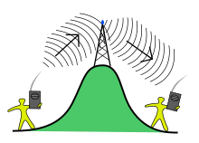
Ground waves are radio waves propagating parallel to and adjacent to the surface of the Earth, following the curvature of the Earth beyond the visible horizon. This radiation is known as Norton surface wave, or more properly Norton ground wave, because ground waves in radio propagation are not confined to the surface.

Path loss, or path attenuation, is the reduction in power density (attenuation) of an electromagnetic wave as it propagates through space. Path loss is a major component in the analysis and design of the link budget of a telecommunication system.

<span class="mw-page-title-main">Transmission medium</span> Conduit for signal propagation

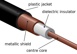
A transmission medium is a system or substance that can mediate the propagation of signals for the purposes of telecommunication. Signals are typically imposed on a wave of some kind suitable for the chosen medium. For example, data can modulate sound, and a transmission medium for sounds may be air, but solids and liquids may also act as the transmission medium. Vacuum or air constitutes a good transmission medium for electromagnetic waves such as light and radio waves. While a material substance is not required for electromagnetic waves to propagate, such waves are usually affected by the transmission media they pass through, for instance, by absorption or reflection or refraction at the interfaces between media. Technical devices can therefore be employed to transmit or guide waves. Thus, an optical fiber or a copper cable is used as transmission media.

<span class="mw-page-title-main">Horizon</span> Apparent curve that separates earth from sky

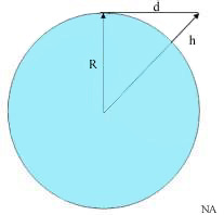
The horizon is the apparent curve that separates the surface of a celestial body from its sky when viewed from the perspective of an observer on or near the surface of the relevant body. This curve divides all viewing directions based on whether it intersects the relevant body's surface or not.

<span class="mw-page-title-main">Very high frequency</span> Electromagnetic wave range of 30-300 MHz

Very high frequency (VHF) is the ITU designation for the range of radio frequency electromagnetic waves from 30 to 300 megahertz (MHz), with corresponding wavelengths of ten meters to one meter. Frequencies immediately below VHF are denoted high frequency (HF), and the next higher frequencies are known as ultra high frequency (UHF).

Rayleigh fading is a statistical model for the effect of a propagation environment on a radio signal, such as that used by wireless devices.

<span class="mw-page-title-main">Radio wave</span> Type of electromagnetic radiation

Radio waves are a type of electromagnetic radiation with the longest wavelengths in the electromagnetic spectrum, typically with frequencies of 300 gigahertz (GHz) and below. At 300 GHz, the corresponding wavelength is 1mm, which is shorter than the diameter of a grain of rice. At 30 Hz the corresponding wavelength is ~10,000 kilometers, which is longer than the radius of the Earth. Wavelength of a radio wave is inversely proportional to its frequency, because its velocity is constant. Like all electromagnetic waves, radio waves in a vacuum travel at the speed of light, and in the Earth's atmosphere at a slightly slower speed. Radio waves are generated by charged particles undergoing acceleration, such as time-varying electric currents. Naturally occurring radio waves are emitted by lightning and astronomical objects, and are part of the blackbody radiation emitted by all warm objects.

<span class="mw-page-title-main">Speed of sound</span> Speed of sound wave through elastic medium

The speed of sound is the distance travelled per unit of time by a sound wave as it propagates through an elastic medium. At 20 °C (68 °F), the speed of sound in air is about 343 m/s, or one km in 2.91 s or one mile in 4.69 s. It depends strongly on temperature as well as the medium through which a sound wave is propagating. At 0 °C (32 °F), the speed of sound in air is about 331 m/s. More simply, the speed of sound is how fast vibrations travel.

<span class="mw-page-title-main">Medium frequency</span> The range 300-3000 kHz of the electromagnetic spectrum

Medium frequency (MF) is the ITU designation for radio frequencies (RF) in the range of 300 kilohertz (kHz) to 3 megahertz (MHz). Part of this band is the medium wave (MW) AM broadcast band. The MF band is also known as the hectometer band as the wavelengths range from ten to one hectometers. Frequencies immediately below MF are denoted as low frequency (LF), while the first band of higher frequencies is known as high frequency (HF). MF is mostly used for AM radio broadcasting, navigational radio beacons, maritime ship-to-shore communication, and transoceanic air traffic control.

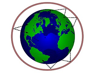
Radio propagation is the behavior of radio waves as they travel, or are propagated, from one point to another in vacuum, or into various parts of the atmosphere. As a form of electromagnetic radiation, like light waves, radio waves are affected by the phenomena of reflection, refraction, diffraction, absorption, polarization, and scattering. Understanding the effects of varying conditions on radio propagation has many practical applications, from choosing frequencies for amateur radio communications, international shortwave broadcasters, to designing reliable mobile telephone systems, to radio navigation, to operation of radar systems.

<span class="mw-page-title-main">Effective radiated power</span> Definition of directional radio frequency power

Effective radiated power (ERP), synonymous with equivalent radiated power, is an IEEE standardized definition of directional radio frequency (RF) power, such as that emitted by a radio transmitter. It is the total power in watts that would have to be radiated by a half-wave dipole antenna to give the same radiation intensity as the actual source antenna at a distant receiver located in the direction of the antenna's strongest beam. ERP measures the combination of the power emitted by the transmitter and the ability of the antenna to direct that power in a given direction. It is equal to the input power to the antenna multiplied by the gain of the antenna. It is used in electronics and telecommunications, particularly in broadcasting to quantify the apparent power of a broadcasting station experienced by listeners in its reception area.

<span class="mw-page-title-main">Skywave</span> Propagation of radio waves beyond the radio horizon.

In radio communication, skywave or skip refers to the propagation of radio waves reflected or refracted back toward Earth from the ionosphere, an electrically charged layer of the upper atmosphere. Since it is not limited by the curvature of the Earth, skywave propagation can be used to communicate beyond the horizon, at intercontinental distances. It is mostly used in the shortwave frequency bands.

In telecommunications, particularly in radio frequency engineering, signal strength refers to the transmitter power output as received by a reference antenna at a distance from the transmitting antenna. High-powered transmissions, such as those used in broadcasting, are expressed in dB-millivolts per metre (dBmV/m). For very low-power systems, such as mobile phones, signal strength is usually expressed in dB-microvolts per metre (dBμV/m) or in decibels above a reference level of one milliwatt (dBm). In broadcasting terminology, 1 mV/m is 1000 μV/m or 60 dBμ.

In astronomy, air mass or airmass is a measure of the amount of air along the line of sight when observing a star or other celestial source from below Earth's atmosphere. It is formulated as the integral of air density along the light ray.

<span class="mw-page-title-main">Atmospheric refraction</span> Deviation of light as it moves through the atmosphere

Atmospheric refraction is the deviation of light or other electromagnetic wave from a straight line as it passes through the atmosphere due to the variation in air density as a function of height. This refraction is due to the velocity of light through air decreasing with increased density. Atmospheric refraction near the ground produces mirages. Such refraction can also raise or lower, or stretch or shorten, the images of distant objects without involving mirages. Turbulent air can make distant objects appear to twinkle or shimmer. The term also applies to the refraction of sound. Atmospheric refraction is considered in measuring the position of both celestial and terrestrial objects.

Non-line-of-sight (NLOS) radio propagation occurs outside of the typical line-of-sight (LOS) between the transmitter and receiver, such as in ground reflections. Near-line-of-sight conditions refer to partial obstruction by a physical object present in the innermost Fresnel zone.

<span class="mw-page-title-main">Radar horizon</span> Distance at which ground targets are hidden

The radar horizon is a critical area of performance for aircraft detection systems that is defined by the distance at which the radar beam rises enough above the Earth's surface to make detection of a target at the lowest level possible. It is associated with the low elevation region of performance, and its geometry depends on terrain, radar height, and signal processing. This is associated with the notions of radar shadow, the clutter zone, and the clear zone.

<span class="mw-page-title-main">Two-ray ground-reflection model</span>

The two-rays ground-reflection model is a multipath radio propagation model which predicts the path losses between a transmitting antenna and a receiving antenna when they are in line of sight (LOS). Generally, the two antenna each have different height. The received signal having two components, the LOS component and the reflection component formed predominantly by a single ground reflected wave.

References

  1. "Line-of-sight propagation". IEEE Technology Navigator. Retrieved 2023-05-10.
  2. Mean radius of the Earth is ≈ 6.37×10⁶ metres = 6370 km. See Earth radius
  3. "P.834 : Effects of tropospheric refraction on radiowave propagation". ITU. 2021-03-05. Retrieved 2021-11-17.
  4. Christopher Haslett. (2008). Essentials of radio wave propagation, pp 119120. Cambridge University Press. ISBN   052187565X.
  5. Busi, R. (1967). High Altitude VHF and UHF Broadcasting Stations. Technical Monograph 3108-1967. Brussels: European Broadcasting Union.
  6. This analysis is for high altitude to sea level reception. In microwave radio link chains, both stations are at high altitudes.