Non-line-of-sight propagation

Last updated

Non-line-of-sight (NLOS) radio propagation occurs outside of the typical line-of-sight (LOS) between the transmitter and receiver, such as in ground reflections. Near-line-of-sight (also NLOS) conditions refer to partial obstruction by a physical object present in the innermost Fresnel zone.

Contents

Obstacles that commonly cause NLOS propagation include buildings, trees, hills, mountains, and, in some cases, high voltage electric power lines. Some of these obstructions reflect certain radio frequencies, while some simply absorb or garble the signals; but, in either case, they limit the use of many types of radio transmissions, especially when low on power budget.

Lower power levels at a receiver reduce the chance of successfully receiving a transmission. Low levels can be caused by at least three basic reasons: low transmit level, for example Wi-Fi power levels; far-away transmitter, such as 3G more than 5 miles (8.0 km) away or TV more than 31 miles (50 km) away; and obstruction between the transmitter and the receiver, leaving no clear path.

NLOS lowers the effective received power. Near Line Of Sight can usually be dealt with using better antennas, but Non Line Of Sight usually requires alternative paths or multipath propagation methods.

How to achieve effective NLOS networking has become one of the major questions of modern computer networking. Currently, the most common method for dealing with NLOS conditions on wireless computer networks is simply to circumvent the NLOS condition and place relays at additional locations, sending the content of the radio transmission around the obstructions. Some more advanced NLOS transmission schemes now use multipath signal propagation, bouncing the radio signal off other nearby objects to get to the receiver.

Non-Line-of-Sight (NLOS) is a term often used in radio communications to describe a radio channel or link where there is no visual line of sight (LOS) between the transmitting antenna and the receiving antenna. In this context LOS is taken

There are many electrical characteristics of the transmission media that affect the radio wave propagation and therefore the quality of operation of a radio channel, if it is possible at all, over an NLOS path.

The acronym NLOS has become more popular in the context of wireless local area networks (WLANs) and wireless metropolitan area networks such as WiMAX because the capability of such links to provide a reasonable level of NLOS coverage greatly improves their marketability and versatility in the typical urban environments where they are most frequently used. However NLOS contains many other subsets of radio communications.

The influence of a visual obstruction on a NLOS link may be anything from negligible to complete suppression. An example might apply to a LOS path between a television broadcast antenna and a roof mounted receiving antenna. If a cloud passed between the antennas the link could actually become NLOS but the quality of the radio channel could be virtually unaffected. If, instead, a large building was constructed in the path making it NLOS, the channel may be impossible to receive.

Beyond line-of-sight (BLOS) is a related term often used in the military to describe radio communications capabilities that link personnel or systems too distant or too fully obscured by terrain for LOS communications. These radios utilize active repeaters, groundwave propagation, tropospheric scatter links, and ionospheric propagation to extend communication ranges from a few kilometers to a few thousand kilometers.

Background

Radio waves as plane electromagnetic waves

From Maxwell's equations [1] we find that radio waves, as they exist in free space in the far field or Fraunhofer region behave as plane waves . [2] [3] In plane waves the electric field, magnetic field and direction of propagation are mutually perpendicular. [4] To understand the various mechanisms that allow successful radio communications over NLOS paths we must consider how such plane waves are affected by the object or objects that visually obstruct the otherwise LOS path between the antennas. It is understood that the terms radio far field waves and radio plane waves are interchangeable.

What is line-of-sight?

By definition, line of sight is the visual line of sight, that is determined by the ability of the average human eye to resolve a distant object. Our eyes are sensitive to light but optical wavelengths are very short compared to radio wavelengths. Optical wavelengths range from about 400 nanometer (nm) to 700 nm but radio wavelengths range from approximately 1 millimeter (mm) at 300 GHz to 30 kilometers (km) at 10 kHz. Even the shortest radio wavelength is therefore about 2000 times longer than the longest optical wavelength. For typical communications frequencies up to about 10 GHz, the difference is on the order of 60,000 times so it is not always reliable to compare visual obstructions, such as might suggest a NLOS path, with the same obstructions as they might affect a radio propagation path.

NLOS links may either be simplex (transmission is in one direction only), duplex (transmission is in both directions simultaneously) or half-duplex (transmission is possible in both directions but not simultaneously). Under normal conditions, all radio links, including NLOSl are reciprocal—which means that the effects of the propagation conditions on the radio channel are identical whether it operates in simplex, duplex, or half-duplex. [5] However, propagation conditions on different frequencies are different, so traditional duplex with different uplink and downlink frequencies is not necessarily reciprocal.

Effect of obstruction size

In general, the way a plane wave is affected by an obstruction depends on the size of the obstruction relative to its wavelength and the electrical properties of the obstruction. For example, a hot air balloon with multi-wavelength dimensions passing between the transmit and receive antennas could be a significant visual obstruction but is unlikely to affect the NLOS radio propagation much assuming it is constructed from fabric and full of hot air, both of which are good insulators. Conversely, a metal obstruction of dimensions comparable to a wavelength would cause significant reflections. When considering obstruction size, we assume its electrical properties are the most common intermediate or lossy type.

Broadly, there are three approximate sizes of obstruction in relationship to a wavelength to consider in a possible NLOS path—those that are:

If the obstruction dimensions are much smaller than the wavelength of the incident plane wave, the wave is essentially unaffected. For example, low frequency (LF) broadcasts, also known as long waves, at about 200 kHz has a wavelength of 1500 m and is not significantly affected by most average size buildings, which are much smaller.

If the obstruction dimensions are of the same order as a wavelength, there is a degree of diffraction around the obstruction and possibly some transmission through it. The incident radio wave could be slightly attenuated and there might be some interaction between the diffracted wavefronts.

If the obstruction has dimensions of many wavelengths, the incident plane waves depend heavily on the electrical properties of the material that forms the obstruction.

Effect of electrical properties of obstructions

The electrical properties of the material forming an obstruction to radio waves could range from a perfect conductor at one extreme to a perfect insulator at the other. Most materials have both conductor and insulator properties. They may be mixed: for example, many NLOS paths result from the LOS path being obstructed by reinforced concrete buildings constructed from concrete and steel. Concrete is quite a good insulator when dry and steel is a good conductor. Alternatively the material may be a homogeneous lossy material.

The parameter that describes to what degree a material is a conductor or insulator is known as , or the loss tangent, given by

where

is the conductivity of the material in siemens per meter (S/m)
is the angular frequency of the RF plane wave in radians per second (rad/s) and is its frequency in hertz (Hz).
is the absolute permittivity of free space in farads per meter (F/m)

and

is the relative permittivity of the material (also known as dielectric constant) and has no units.

Good conductors (poor insulators)

If the material is a good conductor or a poor insulator and substantially reflects the radio waves that are incident upon it with almost the same power. [6] Therefore, virtually no RF power is absorbed by the material itself and virtually none is transmitted, even if it is very thin. All metals are good conductors and there are of course many examples that cause significant reflections of radio waves in the urban environment, for example bridges, metal clad buildings, storage warehouses, aircraft and electrical power transmission towers or pylons.

Good insulators (poor conductors)

If the material is a good insulator (or dielectric) or a poor conductor and substantially transmit waves that are incident upon it. Virtually no RF power is absorbed but some can be reflected at its boundaries depending on its relative permittivity compared to that of free space, which is unity. This uses the concept of intrinsic impedance, which is described below. There are few large physical objects that are also good insulators, with the interesting exception of fresh water icebergs but these do not usually feature in most urban environments. However large volumes of gas generally behave as dielectrics. Examples of these are regions of the Earths atmosphere, which gradually reduce in density at increasing altitudes up to 10 to 20 km. At greater altitudes from about 50 km to 200 km various ionospheric layers also behave like dielectrics and are heavily dependent on the influence of the Sun. Ionospheric layers are not gases but plasmas.

Plane waves and intrinsic impedance

Even if an obstruction is a perfect insulator, it may have some reflective properties on account of its relative permittivity differing from that of the atmosphere. Electrical materials through which plane waves may propagate have a property called intrinsic impedance () or electromagnetic impedance, which is analogous to the characteristic impedance of a cable in transmission line theory. The intrinsic impedance of a homogeneous material is given by: [7]

where

is the absolute permeability in henries per meter (H/m) and is a constant fixed at H/m
is the relative permeability (unitless)
is the absolute permittivity in farads per meter (F/m) and is a constant fixed at F/m
is the relative permittivity or dielectric constant (unitless)

For free space and , therefore the intrinsic impedance of free space is given by

which evaluates to approximately 377 .

Reflection losses at dielectric boundaries

In an analogy of plane wave theory and transmission line theory, the definition of reflection coefficient is a measure of the level of reflection normally at the boundary when a plane wave passes from one dielectric medium to another. For example, if the intrinsic impedance of the first and second media were and respectively, the reflection coefficient of medium 2 relative to 1, , is given by:

The logarithmic measure in decibels () of how the transmitted RF signal over the NLOS link is affected by such a reflection is given by:

Intermediate materials with finite conductivity

Most materials of the type affecting radio wave transmission over NLOS links are intermediate: they are neither good insulators nor good conductors. Radio waves incident upon an obstruction comprising a thin intermediate material are partly reflected at both the incident and exit boundaries and partly absorbed, depending on the thickness. If the obstruction is thick enough the radio wave might be completely absorbed. Because of the absorption, these are often called lossy materials, although the degree of loss is usually extremely variable and often very dependent on the level of moisture present. They are often heterogeneous and comprise a mixture of materials with various degrees of conductor and insulator properties. Such examples are hills, valley sides, mountains (with substantial vegetation) and buildings constructed from stone, brick or concrete but without reinforced steel. The thicker they are the greater the loss. For example, a wall absorbs much less RF power from a normally incident wave than a building constructed from the same material.

Modes

Passive random reflections

Passive random reflections are achieved when plane waves are subject to one or more reflective paths around an object that makes an otherwise LOS radio path into NLOS. The reflective paths might be caused by various objects that could either be metallic (very good conductors such as a steel bridge or an airplane) or relatively good conductors to plane waves such as large expanses of concrete building sides, walls etc. Sometimes this is considered a brute force method because, on each reflection the plane wave undergoes a transmission loss that must be compensated for by a higher output power from the transmit antenna compared to if the link had been LOS. However, the technique is cheap and easy to employ and passive random reflections are widely exploited in urban areas to achieve NLOS. Communication services that use passive reflections include WiFi, WiMax, WiMAX MIMO, mobile (cellular) communications and terrestrial broadcast to urban areas.

Passive repeaters

Passive repeaters may be used to achieve NLOS links by deliberately installing a precisely designed reflector at a critical position to provide a path around the obstruction. However they are unacceptable in most urban environments due to the bulky reflector requiring critical positioning at perhaps an inaccessible location or at one not acceptable to the planning authorities or the owner of the building. Passive reflector NLOS links also incur substantial loss due to the received signal being a 'double inverse-square law' function of the transmit signal, one for each hop from the transmit antenna to the receive antenna. However, they have been successfully used in rural mountainous areas to extend the range of LOS microwave links around mountains, thus creating NLOS links. In such cases the installation of the more usual active repeater was usually not possible due to problems in obtaining a suitable power supply.

Active repeaters

An active repeater is a powered piece of equipment essentially comprising a receiving antenna, a receiver, a transmitter and a transmitting antenna. If the ends of the NLOS link are at positions A and C, the repeater is located at position B where links A-B and B-C are in fact LOS. The active repeater may simply amplify the received signal and re-transmit it un-altered at either the same frequency or a different frequency. The former case is simpler and cheaper but requires good isolation between two antennas to avoid feedback, however it does mean that the end of the NLOS link at A or C does not require to change the receive frequency from that used for a LOS link. A typical application might be to repeat or re-broadcast signals for vehicles using car radios in tunnels. A repeater that changes frequency would avoid any feedback problems but would be more difficult to design and expensive and it would require a receiver to change frequency when moving from the LOS to the NLOS zone.

A communications satellite is an example of an active repeater that does change frequency. Communications satellites, in most cases, are in geosynchronous orbit at an altitude of 22,300 miles (35,000 km) above the Equator.

Groundwave propagation

Application of the Poynting Vector to vertically polarized plane waves at LF (30 kHz to 300 kHz) and VLF (3 kHz to 30 kHz) indicates that a component of the field is propagated a few meters into the surface of the Earth. The propagation is very low loss and communications over thousands of kilometers over NLOS links is possible. However, such low frequencies by definition (Nyquist–Shannon sampling theorem) are very low bandwidth, so this type of communication is not widely used.

Tropospheric modes

Radio waves in the VHF and UHF bands can travel somewhat beyond the visual horizon due to refraction in the troposphere, the bottom layer of the atmosphere below 20 km (12 miles). [8] [9] This is due to changes in the refractive index of air with temperature and pressure. Tropospheric delay is a source of error in radio ranging techniques, such as the Global Positioning System (GPS). [10] In addition, unusual conditions can sometimes allow propagation at greater distances:

Tropospheric refraction

The obstruction that creates an NLOS link may be the Earth itself, such as would exist if the other end of the link was beyond the optical horizon. A very useful property of the Earth's atmosphere is that, on average, the density of air gas molecules reduces as the altitude increases up to approximately 30 km. Its relative permittivity or dielectric constant reduces steadily from about 1.00536 at the Earth's surface. [11] To model the change in refractive index with altitude, the atmosphere may be approximated to many thin air layers, each of which has a slightly smaller refractive index than the one below. The trajectory of radio waves progressing through such an atmosphere model at each interface, is analogous to optical beams passing from one optical medium to another as predicted by Snell's Law. When the beam passes from a higher to lower refractive index it tends to get bent or refracted away from the normal at the boundary according to Snell's Law. When the curvature of the Earth is taken into account it is found that, on average, radio waves whose initial trajectory is towards the optical horizon follows a path that does not return to the Earth's surface at the horizon, but slightly beyond it. The distance from the transmit antenna to where it does return is approximately equivalent to the optical horizon, had the Earth's radius been 4/3 of its actual value. The '4/3 Earth's radius' is a useful rule of thumb to the radio communication engineers when designing such a NLOS link.

The 4/3 Earth radius rule of thumb is an average for the Earth's atmosphere assuming it is reasonably homogenised, absent of temperature inversion layers or unusual meteorological conditions. NLOS links that exploit atmospheric refraction typically operate at frequencies in the VHF and UHF bands, including FM and TV terrestrial broadcast services.

Anomalous propagation

The phenomenon described above that the atmospheric refractive index, relative permittivity or dielectric constant gradually reduces with increasing height is on account of the reduction of the atmospheric air density with increasing height. Air density is also a function of temperature, which ordinarily also reduces with increasing height. However, these are only average conditions; local meteorological conditions can create phenomena such as temperature inversion layers where a warm layer of air settles above a cool layer. At the interface between them exists a relatively abrupt change in refractive index from a smaller value in the cool layer to a larger value in the warm layer. By analogy with the optical Snell's Law, this can cause significant reflections of radio waves back towards the Earth's surface where they are further reflected, thus causing a ducting effect. The result is that radio waves can propagate well beyond their intended service area with less than normal attenuation. This effect is only apparent in the VHF and UHF spectra and is often exploited by amateur radio enthusiasts to achieve communications over abnormally long distances for the frequencies involved. [12] For commercial communication services it cannot be exploited because it is unreliable (the conditions can form and disperse in minutes) and it can cause interference well outside of the normal service area.

Temperature inversion and anomalous propagation can occur at most latitudes but they are more common in tropical climates than temperate climates, usually associated with high pressure areas (anticyclones).

Tropospheric ducting

Sudden changes in the atmosphere's vertical moisture content and temperature profiles can on random occasions make UHF, VHF and microwave signals propagate hundreds of kilometers (miles) up to about 2,000 kilometers (1,200 miles)and for ducting mode even fartherbeyond the normal radio-horizon. The inversion layer is mostly observed over high pressure regions, but there are several tropospheric weather conditions which create these randomly occurring propagation modes. Inversion layer's altitude for non-ducting is typically found between 100 and 1,000 meters (330 and 3,280 feet) and for ducting about 500 to 3,000 meters (1,600 to 9,800 feet), and the duration of the events are typically from several hours up to several days. Higher frequencies experience the most dramatic increase of signal strengths, while on low-VHF and HF the effect is negligible. Propagation path attenuation may be below free-space loss. Some of the lesser inversion types related to warm ground and cooler air moisture content occur regularly at certain times of the year and time of day. A typical example could be the late summer, early morning tropospheric enhancements that bring in signals from distances up to few hundred kilometers (miles) for a couple of hours, until undone by the Sun's warming effect.

Tropospheric scattering (troposcatter)

At VHF and higher frequencies, small variations (turbulence) in the density of the atmosphere at a height of around 6 miles (9.7 km) can scatter some of the normally line-of-sight beam of radio frequency energy back toward the ground. In tropospheric scatter (troposcatter) communication systems a powerful beam of microwaves is aimed above the horizon, and a high gain antenna over the horizon aimed at the section of the troposphere though which the beam passes receives the tiny scattered signal. Troposcatter systems can achieve over-the-horizon communication between stations 500 miles (800 km) apart, and the military developed networks such as the White Alice Communications System covering all of Alaska before the 1960s, when communication satellites largely replaced them.

A tropospheric scatter NLOS link typically operates at a few gigahertz using potentially very high transmit powers (typically 3 kW to 30 kW, depending on conditions), very sensitive receivers and very high gain, usually fixed, large reflector antennas. The transmit beam is directed into the troposphere just above the horizon with sufficient power flux density that gas and water vapour molecules cause scattering in a region in the beam path known as the scatter volume. Some components of the scattered energy travel in the direction of the receiver antennas and form the receive signal. Since there are very many particles to cause scattering in this region, the Rayleigh fading statistical model may usefully predict behaviour and performance in this kind of system.

Rain scattering

Rain scattering is purely a microwave propagation mode and is best observed around 10 GHz, but extends down to a few gigahertz—the limit being the size of the scattering particle size vs. wavelength. This mode scatters signals mostly forwards and backwards when using horizontal polarization and side-scattering with vertical polarization. Forward-scattering typically yields propagation ranges of 800 km (500 miles). Scattering from snowflakes and ice pellets also occurs, but scattering from ice without watery surface is less effective. The most common application for this phenomenon is microwave rain radar, but rain scatter propagation can be a nuisance causing unwanted signals to intermittently propagate where they are not anticipated or desired. Similar reflections may also occur from insects though at lower altitudes and shorter range. Rain also causes attenuation of point-to-point and satellite microwave links. Attenuation values up to 30 dB have been observed on 30 GHz during heavy tropical rain.

Lightning scattering

Lightning scattering has sometimes been observed on VHF and UHF over distances of about 500 km (300 miles). The hot lightning channel scatters radio-waves for a fraction of a second. The RF noise burst from the lightning makes the initial part of the open channel unusable and the ionization disappears quickly because of recombination at low altitude and high atmospheric pressure. Although the hot lightning channel is briefly observable with microwave radar, no practical use for this mode has been found in communications.

Ionospheric propagation

The mechanism of ionospheric propagation in supporting NLOS links is similar to that for atmospheric refraction but, in this case, the radio wave refraction occurs not in the atmosphere but in the ionosphere at much greater altitudes. [13] Like its tropospheric counterpart, ionospheric propagation can sometimes be statistically modelled using Rayleigh fading.

The ionosphere extends from altitudes of approximately 50 km to 400 km and is divided into distinct plasma layers denoted D, E, F1, and F2 in increasing altitude. Refraction of radio waves by the ionosphere rather than the atmosphere can therefore allow NLOS links of much greater distance for just one refraction path or 'hop' via one of the layers. Under certain conditions radio waves that have undergone one hop may reflect off the Earth's surface and experience more hops, so increasing the range. The positions of these and their ion densities are significantly controlled by the Sun's incident radiation and therefore change diurnally, seasonally and during Sun spot activity. The initial discovery that radio waves could travel beyond the horizon by Marconi in the early 20th century prompted extensive studies of ionospheric propagation for the next 50 years or so, which have yielded various HF link channel prediction tables and charts.

Frequencies that are affected by ionospheric propagation range from approximately 500 kHz to 50 MHz but the majority of such NLOS links operate in the 'short wave' or high frequency (HF) frequency bands between 3 MHz and 30 MHz.

In the latter half of the twentieth century, alternative means of communicating over large NLOS distances were developed such as satellite communications and submarine optical fiber, both of which potentially carry much larger bandwidths than HF and are much more reliable. Despite their limitations, HF communications only need relatively cheap, crude equipment and antennas so they are mostly used as backups to main communications systems and in sparsely populated remote areas where other methods of communication are not cost effective.

Discussion
Sky Wave Propagation Sky Wave Propagation.svg
Sky Wave Propagation

Skywave propagation, also referred to as skip, is any of the modes that rely on reflection and refraction of radio waves from the ionosphere. The ionosphere is a region of the atmosphere from about 60 to 500 km (37 to 311 mi) that contains layers of charged particles (ions) which can refract a radio wave back toward the Earth. A radio wave directed at an angle into the sky can be reflected back to Earth beyond the horizon by these layers, allowing long-distance radio transmission. The F2 layer is the most important ionospheric layer for long-distance, multiple-hop HF propagation, though F1, E, and D-layers also play significant roles. The D-layer, when present during sunlight periods, causes significant amount of signal loss, as does the E-layer whose maximum usable frequency can rise to 4 MHz and above and thus block higher frequency signals from reaching the F2-layer. The layers, or more appropriately "regions", are directly affected by the sun on a daily diurnal cycle, a seasonal cycle and the 11-year sunspot cycle and determine the utility of these modes. During solar maxima, or sunspot highs and peaks, the whole HF range up to 30 MHz can be used usually around the clock and F2 propagation up to 50 MHz is observed frequently depending upon daily solar flux values. During solar minima, or minimum sunspot counts down to zero, propagation of frequencies above 15 MHz is generally unavailable.

Although the claim is commonly made that two-way HF propagation along a given path is reciprocal, that is, if the signal from location A reaches location B at a good strength, the signal from location B will be similar at station A because the same path is traversed in both directions. However, the ionosphere is far too complex and constantly changing to support the reciprocity theorem. The path is never exactly the same in both directions. [14] In brief, conditions at the two end-points of a path generally cause dissimilar polarization shifts, hence dissimilar splits into ordinary rays and extraordinary rays (Pedersen rays) which have different propagation characteristics due to differences in ionization density, shifting zenith angles, effects of the Earth's magnetic dipole contours, antenna radiation patterns, ground conditions, and other variables.

Forecasting of skywave modes is of considerable interest to amateur radio operators and commercial marine and aircraft communications, and also to shortwave broadcasters. Real-time propagation can be assessed by listening for transmissions from specific beacon transmitters.

Finite absorption

If an object that changes a LOS link to NLOS is not a good conductor but an intermediate material, it absorbs some of the RF power incident upon it. However, if it has finite thickness the absorption is also finite and the resulting attenuation of the radio waves may be tolerable and an NLOS link may be set up using radio waves that actually pass through the material. As an example, WLANs often use finite absorption NLOS links to communicate between a WLAN access point and WLAN client(s) in the typical office environment. The radio frequencies used, typically a few gigahertz (GHz) normally passes through a few thin office walls and partitions with tolerable attenuation. After many such walls though or after a few thick concrete or similar (non-metallic) walls the NLOS link becomes unworkable.

Meteor scattering

Meteor scattering relies on reflecting radio waves off the intensely ionized columns of air generated by meteors. While this mode is very short duration, often only from a fraction of second to couple of seconds per event, digital Meteor burst communications allows remote stations to communicate to a station that may be hundreds of miles up to over 1,000 miles (1,600 km) away, without the expense required for a satellite link. This mode is most generally useful on VHF frequencies between 30 and 250 MHz.

Auroral backscatter

Intense columns of Auroral ionization at 100 km (60 mile) altitudes within the auroral oval backscatter radio waves, including those on HF and VHF. Backscatter is angle-sensitive—incident ray vs. magnetic field line of the column must be very close to right-angle. Random motions of electrons spiraling around the field lines create a Doppler-spread that broadens the spectra of the emission to more or less noise-like – depending on how high radio frequency is used. The radio-auroras are observed mostly at high latitudes and rarely extend down to middle latitudes. The occurrence of radio-auroras depends on solar activity (flares, coronal holes, CMEs) and annually the events are more numerous during solar cycle maxima. Radio aurora includes the so-called afternoon radio aurora which produces stronger but more distorted signals and after the Harang-minima, the late-night radio aurora (sub-storming phase) returns with variable signal strength and lesser doppler spread. The propagation range for this predominantly back-scatter mode extends up to about 2000 km (1250 miles) in east–west plane, but strongest signals are observed most frequently from the north at nearby sites on same latitudes.

Rarely, a strong radio-aurora is followed by Auroral-E, which resembles both propagation types in some ways.

Sporadic-E propagation

Sporadic E (Es) propagation occurs on HF and VHF bands. [15] It must not be confused with ordinary HF E-layer propagation. Sporadic-E at mid-latitudes occurs mostly during summer season, from May to August in the northern hemisphere and from November to February in the southern hemisphere. There is no single cause for this mysterious propagation mode. The reflection takes place in a thin sheet of ionization around 90 km (55 miles) height. The ionization patches drift westwards at speeds of few hundred km (miles) per hour. There is a weak periodicity noted during the season and typically Es is observed on 1 to 3 successive days and remains absent for a few days to reoccur again. Es do not occur during small hours; the events usually begin at dawn, and there is a peak in the afternoon and a second peak in the evening. [16] Es propagation is usually gone by local midnight.

Observation of radio propagation beacons operating around 28.2 MHz, 50 MHz and 70 MHz, indicates that maximum observed frequency (MOF) for Es is found to be lurking around 30 MHz on most days during the summer season, but sometimes MOF may shoot up to 100 MHz or even more in ten minutes to decline slowly during the next few hours. The peak-phase includes oscillation of MOF with periodicity of approximately 5...10 minutes. The propagation range for Es single-hop is typically 1000 to 2000 km (600 to 1250 miles), but with multi-hop, double range is observed. The signals are very strong but also with slow deep fading.

Airplane scattering

Airplane scattering (or most often reflection) is observed on VHF through microwaves and, besides back-scattering, yields momentary propagation up to 500 km (300 miles) even in mountainous terrain. The most common back-scatter applications are air-traffic radar, bistatic forward-scatter guided-missile and airplane-detecting trip-wire radar, and the US space radar.

Earth–Moon–Earth communication

Earth–Moon–Earth communication (EME), also known as Moon bounce, is a radio communications technique that relies on the propagation of radio waves from an Earth-based transmitter directed via reflection from the surface of the Moon back to an Earth-based receiver.

Other effects

Diffraction

Knife-edge diffraction is the propagation mode where radio waves are bent around sharp edges. For example, this mode is used to send radio signals over a mountain range when a line-of-sight path is not available. However, the angle cannot be too sharp or the signal will not diffract. The diffraction mode requires increased signal strength, so higher power or better antennas will be needed than for an equivalent line-of-sight path.

Diffraction depends on the relationship between the wavelength and the size of the obstacle. In other words, the size of the obstacle in wavelengths. Lower frequencies diffract around large smooth obstacles such as hills more easily. For example, in many cases where VHF (or higher frequency) communication is not possible due to shadowing by a hill, it is still possible to communicate using the upper part of the HF band where the surface wave is of little use.

Diffraction phenomena by small obstacles are also important at high frequencies. Signals for urban cellular telephony tend to be dominated by ground-plane effects as they travel over the rooftops of the urban environment. They then diffract over roof edges into the street, where multipath propagation, absorption and diffraction phenomena dominate.

Absorption

Low-frequency radio waves travel easily through brick and stone and VLF even penetrates sea-water. As the frequency rises, absorption effects become more important. At microwave or higher frequencies, absorption by molecular resonances in the atmosphere (mostly from water, H2O and oxygen, O2) is a major factor in radio propagation. For example, in the 58–60 GHz band, there is a major absorption peak which makes this band useless for long-distance use. This phenomenon was first discovered during radar research in World War II. Above about 400 GHz, the Earth's atmosphere blocks most of the spectrum while still passing some - up to UV light, which is blocked by ozone - but visible light and some of the near-infrared is transmitted. Heavy rain and falling snow also affect microwave absorption.

Effect on positioning

In most of the recent localization systems, it is assumed that the received signals propagate through a LOS path. However, infringement of this assumption can result in inaccurate positioning data. [17] For Time of Arrival based localization system, the emitted signal can only arrive at the receiver through its NLOS paths. The NLOS error is defined as the extra distance travelled by the received signal with respect to the LOS path. The NLOS error is always positively biased with the magnitude dependent on the propagation environment.

Related Research Articles

<span class="mw-page-title-main">Ionosphere</span> Ionized part of Earths upper atmosphere

The ionosphere is the ionized part of the upper atmosphere of Earth, from about 48 km (30 mi) to 965 km (600 mi) above sea level, a region that includes the thermosphere and parts of the mesosphere and exosphere. The ionosphere is ionized by solar radiation. It plays an important role in atmospheric electricity and forms the inner edge of the magnetosphere. It has practical importance because, among other functions, it influences radio propagation to distant places on Earth.

In telecommunication, the term critical frequency has the following meanings:

The F region of the ionosphere is home to the F layer of ionization, also called the Appleton–Barnett layer, after the English physicist Edward Appleton and New Zealand physicist and meteorologist Miles Barnett. As with other ionospheric sectors, 'layer' implies a concentration of plasma, while 'region' is the volume that contains the said layer. The F region contains ionized gases at a height of around 150–800 km above sea level, placing it in the Earth's thermosphere, a hot region in the upper atmosphere, and also in the heterosphere, where chemical composition varies with height. Generally speaking, the F region has the highest concentration of free electrons and ions anywhere in the atmosphere. It may be thought of as comprising two layers, the F1 and F2 layers.

Ground waves are radio waves propagating parallel to and adjacent to the surface of the Earth, following the curvature of the Earth. This radiation is known as Norton surface wave, or more properly Norton ground wave, because ground waves in radio propagation are not confined to the surface.

Path loss, or path attenuation, is the reduction in power density (attenuation) of an electromagnetic wave as it propagates through space. Path loss is a major component in the analysis and design of the link budget of a telecommunication system.

<span class="mw-page-title-main">Transmission medium</span> Conduit for signal propagation

A transmission medium is a system or substance that can mediate the propagation of signals for the purposes of telecommunication. Signals are typically imposed on a wave of some kind suitable for the chosen medium. For example, data can modulate sound, and a transmission medium for sounds may be air, but solids and liquids may also act as the transmission medium. Vacuum or air constitutes a good transmission medium for electromagnetic waves such as light and radio waves. While material substance is not required for electromagnetic waves to propagate, such waves are usually affected by the transmission media they pass through, for instance, by absorption or reflection or refraction at the interfaces between media. Technical devices can therefore be employed to transmit or guide waves. Thus, an optical fiber or a copper cable is used as transmission media.

<span class="mw-page-title-main">Coaxial cable</span> Electrical cable type with concentric inner conductor, insulator, and conducting shield

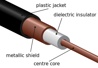
Coaxial cable, or coax is a type of electrical cable consisting of an inner conductor surrounded by a concentric conducting shield, with the two separated by a dielectric ; many coaxial cables also have a protective outer sheath or jacket. The term coaxial refers to the inner conductor and the outer shield sharing a geometric axis.

<span class="mw-page-title-main">Line-of-sight propagation</span> Characteristic of electromagnetic radiation

Line-of-sight propagation is a characteristic of electromagnetic radiation or acoustic wave propagation which means waves travel in a direct path from the source to the receiver. Electromagnetic transmission includes light emissions traveling in a straight line. The rays or waves may be diffracted, refracted, reflected, or absorbed by the atmosphere and obstructions with material and generally cannot travel over the horizon or behind obstacles.

<span class="mw-page-title-main">Very high frequency</span> Electromagnetic wave range of 30-300 MHz

Very high frequency (VHF) is the ITU designation for the range of radio frequency electromagnetic waves from 30 to 300 megahertz (MHz), with corresponding wavelengths of ten meters to one meter. Frequencies immediately below VHF are denoted high frequency (HF), and the next higher frequencies are known as ultra high frequency (UHF).

<span class="mw-page-title-main">Radio wave</span> Type of electromagnetic radiation

Radio waves are a type of electromagnetic radiation with the longest wavelengths in the electromagnetic spectrum, typically with frequencies of 300 gigahertz (GHz) and below. At 300 GHz, the corresponding wavelength is 1 mm ; at 30 Hz the corresponding wavelength is 10,000 kilometers. Like all electromagnetic waves, radio waves in a vacuum travel at the speed of light, and in the Earth's atmosphere at a close, but slightly lower speed. Radio waves are generated by charged particles undergoing acceleration, such as time-varying electric currents. Naturally occurring radio waves are emitted by lightning and astronomical objects, and are part of the blackbody radiation emitted by all warm objects.

<span class="mw-page-title-main">Medium frequency</span> The range 300-3000 kHz of the electromagnetic spectrum

Medium frequency (MF) is the ITU designation for radio frequencies (RF) in the range of 300 kilohertz (kHz) to 3 megahertz (MHz). Part of this band is the medium wave (MW) AM broadcast band. The MF band is also known as the hectometer band as the wavelengths range from ten to one hectometer. Frequencies immediately below MF are denoted low frequency (LF), while the first band of higher frequencies is known as high frequency (HF). MF is mostly used for AM radio broadcasting, navigational radio beacons, maritime ship-to-shore communication, and transoceanic air traffic control.

<span class="mw-page-title-main">High frequency</span> The range 3-30 MHz of the electromagnetic spectrum

High frequency (HF) is the ITU designation for the range of radio frequency electromagnetic waves between 3 and 30 megahertz (MHz). It is also known as the decameter band or decameter wave as its wavelengths range from one to ten decameters. Frequencies immediately below HF are denoted medium frequency (MF), while the next band of higher frequencies is known as the very high frequency (VHF) band. The HF band is a major part of the shortwave band of frequencies, so communication at these frequencies is often called shortwave radio. Because radio waves in this band can be reflected back to Earth by the ionosphere layer in the atmosphere – a method known as "skip" or "skywave" propagation – these frequencies are suitable for long-distance communication across intercontinental distances and for mountainous terrains which prevent line-of-sight communications. The band is used by international shortwave broadcasting stations (3.95–25.82 MHz), aviation communication, government time stations, weather stations, amateur radio and citizens band services, among other uses.

TV DX and FM DX is the active search for distant radio or television stations received during unusual atmospheric conditions. The term DX is an old telegraphic term meaning "long distance."

Radio propagation is the behavior of radio waves as they travel, or are propagated, from one point to another in vacuum, or into various parts of the atmosphere. As a form of electromagnetic radiation, like light waves, radio waves are affected by the phenomena of reflection, refraction, diffraction, absorption, polarization, and scattering. Understanding the effects of varying conditions on radio propagation has many practical applications, from choosing frequencies for amateur radio communications, international shortwave broadcasters, to designing reliable mobile telephone systems, to radio navigation, to operation of radar systems.

<span class="mw-page-title-main">Skywave</span> Propagation of radio waves beyond the radio horizon.

In radio communication, skywave or skip refers to the propagation of radio waves reflected or refracted back toward Earth from the ionosphere, an electrically charged layer of the upper atmosphere. Since it is not limited by the curvature of the Earth, skywave propagation can be used to communicate beyond the horizon, at intercontinental distances. It is mostly used in the shortwave frequency bands.

Earth–Moon–Earth communication (EME), also known as Moon bounce, is a radio communications technique that relies on the propagation of radio waves from an Earth-based transmitter directed via reflection from the surface of the Moon back to an Earth-based receiver.

Near vertical incidence skywave, or NVIS, is a skywave radio-wave propagation path that provides usable signals in the medium distances range — usually 0–650 km. It is used for military and paramilitary communications, broadcasting, especially in the tropics, and by radio amateurs for nearby contacts circumventing line-of-sight barriers. The radio waves travel near-vertically upwards into the ionosphere, where they are refracted back down and can be received within a circular region up to 650 km from the transmitter. If the frequency is too high, refraction is insufficient to return the signal to earth and if it is too low, absorption in the ionospheric D layer may reduce the signal strength.

Amateur radio frequency allocation is done by national telecommunication authorities. Globally, the International Telecommunication Union (ITU) oversees how much radio spectrum is set aside for amateur radio transmissions. Individual amateur stations are free to use any frequency within authorized frequency ranges; authorized bands may vary by the class of the station license.

This is an index to articles about terms used in discussion of radio propagation.

<span class="mw-page-title-main">Metamaterial antenna</span>

Metamaterial antennas are a class of antennas which use metamaterials to increase performance of miniaturized antenna systems. Their purpose, as with any electromagnetic antenna, is to launch energy into free space. However, this class of antenna incorporates metamaterials, which are materials engineered with novel, often microscopic, structures to produce unusual physical properties. Antenna designs incorporating metamaterials can step-up the antenna's radiated power.

References

  1. Pozar, David M. (2005); Microwave Engineering, Third Edition (Intl. Ed.); John Wiley & Sons, Inc.; pp 5-9. ISBN   0-471-44878-8.
  2. Ramo, Whinnery and Van Duzer;"Fields and Waves in Communication Electronics"; John Wiley & Sons, Inc; pp 322-324. ISBN   0-471-58551-3
  3. Morton, A H; "Advanced Electrical Engineering"; Pitman Publishing Ltd.; pp 387-389. ISBN   0-273-40172-6.
  4. A. J. Baden Fuller;"Microwaves, Second Edition"; Pergammon Press; p 47. ISBN   0-08-024228-6.
  5. Ramo, Whinnery and Van Duzer (op. cit); pp 717-719.
  6. A. J. Baden Fuller (op. cit.); p152
  7. A. J. Baden Fuller (op. cit.); pp45-47
  8. "Tropospheric propagation". Electronics-notes.com. 2016. Retrieved March 3, 2017.
  9. Kleijer, Frank (2004). Troposphere Modeling and Filtering for Precise GPS Leveling (PDF). Department of Mathematical Geodesy and Positioning (Ph.D. thesis). Delft, NL: Delft University of Technology. Archived from the original (PDF) on 2008-09-07.
  10. Tennent, R. M. (Ed.); "Science Data Book; The Open University; p66
  11. Hutchinson, Chuck K8CH; "The ARRL Handbook for Radio Amateurs 2001 78th Ed.";The American Radio Relay League, Inc. ISBN   0-87259-186-7
  12. Kennedy, George (1993). Electronic Communication Systems. MacMillan/McGraw-Hill. ISBN   0-07-112672-4.
  13. Hull, G.W. (March 1967). "Nonreciprocal characteristics of a 1500 km HF ionospheric path". Proceedings of the IEEE. 55 (3): 426–427. doi:10.1109/PROC.1967.5516;Jull, G. W.; Pettersen, G. W. E. (1964). "Origin of non-reciprocity on high-frequency ionospheric paths". Nature. 201 (4918): 483–484. Bibcode:1964Natur.201..483J. doi:10.1038/201483a0. S2CID   4181453, and cited references.[ full citation needed ]
  14. Davies, Kenneth (1990). Ionospheric Radio. IEE Electromagnetic Waves Series. Vol. 31. London, UK: Peter Peregrinus Ltd / The Institution of Electrical Engineers. pp. 184–186. ISBN   0-86341-186-X.
  15. Jacobs, George and Cohen, Theodore J. (1982). Shortwave Propagation Handbook. Hicksville, NY: CQ Publishing. pp. 130–135. ISBN   978-0-943016-00-9.
  16. Wang Wei; Xiong Jin-Yu; Zhu Zhong-Liang (2005). "A new NLOS mitigation algorithm in location estimation". IEEE Transactions on Vehicular Technology. IEEE Vehicular Technology Society. 54 (6): 2048–2053. doi:10.1109/TVT.2005.858177. ISSN   0018-9545.

Further reading