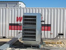
An air-cooled load bank, being used for acceptance testing of a 3000 kW standby diesel generator set. This is one of three banks used to load the generator to verify performance on load changes and for factory run-in.
A load bank is a piece of electrical test equipment used to simulate an electrical load, to test an electric power source without connecting it to its normal operating load.[1][2] During testing, adjustment, calibration, or verification procedures, a load bank is connected to the output of a power source, such as an electric generator, battery, servoamplifier or photovoltaic system, in place of its usual load. The load bank presents the source with electrical characteristics similar to its standard operating load, while dissipating the power output that would normally be consumed by it. The power is usually converted to heat by a heavy duty resistor or bank of resistive heating elements in the device, and the heat removed by a forced air or water cooling system. The device usually also includes instruments for metering, load control, and overload protection. Load banks can either be permanently installed at a facility to be connected to a power source when needed, or portable versions can be used for testing power sources such as standby generators and batteries. They are necessary adjuncts to replicate, prove, and verify the real-life demands on critical power systems.[2] They are also used during operation of intermittent renewable power sources such as wind turbines to shed excess power that the electric power grid cannot absorb.[3]
Data center tests (electricity and air-conditioning)
Load bank types
The three most common types of load banks are resistive, inductive, and capacitive. Both inductive and capacitive loads create what is known as reactance in an AC circuit. Reactance is a circuit element's opposition to an alternating current, caused by the buildup of electric or magnetic fields in the element due to the current and is the "imaginary" component of impedance, or the resistance to AC signals at a certain frequency. Capacitive reactance is equal to 1/(2⋅π⋅f⋅C), and inductive reactance is equal to 2⋅π⋅f⋅L. The unit of reactance is the ohm. Inductive reactance resists the change to current, causing the circuit current to lag voltage. Capacitive reactance resists the change to voltage, causing the circuit current to lead voltage.
Resistive load bank
A resistive load bank, the most common type, provides equivalent loading for both generators and prime movers. That is, for each kilowatt (or horsepower) of load applied to the generator by the load bank, an equal amount of load is applied to the prime mover by the generator. A resistive load bank, therefore, removes energy from the complete system: load bank from generator—generator from prime mover—prime mover from fuel. Additional energy is removed as a consequence of resistive load bank operation: waste heat from coolant, exhaust and generator losses and energy consumed by accessory devices. A resistive load bank impacts upon all aspects of a generating system.
An operator controlling a resistive 200kW load bank being used to test a diesel generator.
The load of a resistive load bank is created by the conversion of electrical energy to heat via high-power resistors such as grid resistors. This heat must be dissipated from the load bank, either by air or by water, by forced means or convection.
In a testing system, a resistive load simulates real-life resistive loads, such as incandescent lighting and heating loads as well as the resistive or unity power factor component of magnetic (motors, transformers) loads.
The most common type uses wire resistance, usually with fan cooling, and this type is often portable and moved from generator to generator for test purposes. Sometimes a load of this type is built into a building, but this is unusual.[4]
Rarely a salt water rheostat is used. It can be readily improvised, which makes it useful in remote locations.
For testing automotive batteries, a carbon pile load bank allows an adjustable load to be placed on the battery or charging system, allowing accurate simulation of the heavy load on the battery during cranking of the engine. Such devices are usually portable and may include metering to show voltage and current.[5]
Inductive load bank
An inductive load includes inductive (lagging power factor) loads.
An inductive load consists of an iron-core reactive element which, when used in conjunction with a resistive load bank, creates a lagging power factor load. Typically, the inductive load will be rated at a numeric value 75% that of the corresponding resistive load such that when applied together a resultant 0.8 power factor load is provided. That is to say, for each 100kW of resistive load, 75 kVAr of inductive load is provided. Other ratios are possible to obtain other power factor ratings. An inductive load is used to simulate a real-life mixed commercial loads consisting of lighting, heating, motors, transformers, etc. With a resistive-inductive load bank, full power system testing is possible, because the provided impedance supplies currents out of phase with voltage and allows for performance evaluation of generators, voltage regulators, load tap changers, conductors, switchgear and other equipment.[4]
Capacitor bank.
Capacitive load bank
A capacitive load bank or capacitor bank is similar to an inductive load bank in rating and purpose, except leading power factor loads are created, so reactive power is supplied from these loads to the system instead of vice versa. Hence for a mostly inductive load this can bring the power factor closer to unity improving the quality of supply. These loads simulate certain electronic or non-linear loads typical of telecommunications, computer or UPS industries. Fluorescent light tubes are also capacitive loads.
Resistive Reactive (Combined) load bank
A combined load bank usually consists of both resistive elements and inductors that can be used to provide load testing at non-unity PF (lagging) including the capability to test the generator set fully at 100% nameplate kVA rating. Combined load banks incorporate resistors and inductors all in a single construction which can be independently switched to allow resistive only, inductive only, or varying lagging power factor testing. Combined load banks are rated in kilovolt-amperes (kVA). It’s worth noting that combined load banks can consist of resistive, inductive, and capacitive (RLC) also.[2]
Typically, facilities require motor-driven devices, transformers and capacitors. If this is the case, then the load banks used for testing require reactive power compensation. The ideal solution is a combination of both resistive and reactive elements in one load bank package.
Resistive/reactive loads are able to mimic motor loads and electromagnetic devices within a power system, as well as provide purely resistive loads.
Many backup generators and turbines need to be commissioned at nameplate capacity using a combination of resistive and reactive load to fully qualify their operating capability. Using a resistive/reactive load bank enables comprehensive testing from a single unit. A range of resistive/reactive load banks are available to simulate these types of loads on a power source and the transformers, relays and switches which will distribute the power throughout the facility.
Resistive/reactive load banks may be used for testing turbines, switchgear, rotary UPS, generators and UPS systems. They can also be used for integrated system testing of utility substation protection systems, particularly for more complex relays like distance, directional overcurrent, power directional and others. A resistive/reactive inductive and/or capacitive load is often required to test solar inverters to ensure solar panels can be stopped from producing electricity in the event of a power outage. The resistive/reactive combination load banks are used to test the engine generator set at its rated power factor. In most cases this is 0.8 power factor.[6]
Electronic load bank
An electronic load bank tends to be a fully programmable, air- or water-cooled design used to simulate a solid state load and to provide constant power and current loading on circuits for precision testing.
On electric railways, old electric locomotives no longer required for regular service sometimes get converted into mobile load banks for testing the overhead line equipment and power distribution systems.[7]
↑ Bayer, Gareth (2021-09-13). "Locos of the RTC (Part 2b)". Rail Express. No.305. Horncastle. pp.78–79. ISSN1362-234X.
This page is based on this Wikipedia article Text is available under the CC BY-SA 4.0 license; additional terms may apply. Images, videos and audio are available under their respective licenses.