Low-voltage network

Last updated
A pole-mounted three-phase distribution transformer. Low-voltage feeders distributing power to households are placed below the transformer PoleMountedDistributionTransformerNZ.jpg
A pole-mounted three-phase distribution transformer. Low-voltage feeders distributing power to households are placed below the transformer

A low-voltage network or secondary network is a part of electric power distribution which carries electric energy from distribution transformers to electricity meters of end customers. Secondary networks are operated at a low voltage level, which is typically equal to the mains voltage of electric appliances.

Contents

Most modern secondary networks are operated at AC rated voltage of 100–127 or 220–240  volts, at the frequency of 50 or 60  hertz (see mains electricity by country). Operating voltage, required number of phases (three-phase or single-phase) and required reliability dictate topology and configuration of the network. The simplest form are radial service drop lines from the transformer to the customer premises. Low-voltage radial feeders supply multiple customers. For increased reliability, so-called spot networks and grid networks provide supply of customers from multiple distribution transformers and supply paths. Electric wiring can be realized by overhead power lines, aerial or underground power cables, or their mixture.

Overview

A house cable connection cabinet equipped with a meter, a time switch and a circuit breaker Elektromerovy rozvadec PER 2.JPG
A house cable connection cabinet equipped with a meter, a time switch and a circuit breaker

Electric power distribution systems are designed to serve their customers with reliable and high-quality power. The most common distribution system consists of simple radial circuits (feeders) that can be overhead, underground, or a combination. From the distribution substation, feeders carry the power to the end customers, forming the medium-voltage or primary network, operated at a medium voltage level, typically 5–35 kV. Feeders range in length from a few kilometers to several tens of kilometers. As they must supply all customers in the designated distribution area, they often curve and branch along the assigned corridors. [1] [2] A substation typically supplies 3–30 feeders.[ citation needed ]

Distribution transformers or secondary transformers, placed along feeders, convert the voltage from the medium to a low voltage level, suitable for direct consumption by end customers (mains voltage). [3] Typically, a rural primary feeder supplies up to 50 distribution transformers, spread over a wide region, [4] but the figure significantly varies depending on configuration. They are sited on pole tops, cellars or designated small plots. [2] From these transformers, low-voltage or secondary network branches off to the customer connections at customer premises, equipped with electricity meters. [3]

Design considerations

Typical layouts of European (left) and North American (right) distribution system
European Distribution System.svg
American Distribution System.svg

Most of differences in the layout and design of low-voltage networks are dictated by the mains voltage rating. In Europe and most of the world 220–240 V is the dominant choice, while in North America 120 V is the standard. [5]

ANSI standard C84.1 recommends a +5%, −2.5% tolerance for the voltage range at a service point. [6] North American LV networks feature much shorter secondary connections, up to 250 feet (80 m), while in European design they can reach up to 1 mile (1,600 m). North American distribution transformers must be therefore placed much closer to consumers, and are smaller (25–50 kVA), while European ones can cover larger areas and thus have higher ratings (300–1000 kVA); only the remote rural areas in European design are served by single-phase transformers. [5]

As the low-voltage distribute the electric power to the widest class of end users, another main design concern is safety of consumers who use the electric appliances and their protection against electric shocks. An earthing system, in combination with protective devices such as fuses and residual current devices, must ultimately ensure that a person must not come into touch with a metallic object whose potential relative to the person's potential (which is, in turn, equal to the ground potential unless insulating mats are used) exceeds a "safe" threshold, typically set at about 50 V.

Topology

Radial networks

Typical layouts of radial low-voltage networks Radial Networks.svg
Typical layouts of radial low-voltage networks

Radial operation is the most widespread and most economic design of both MV and LV networks. It provides a sufficiently high degree of reliability and service continuity for most customers. [7] In American (120 V) systems, the customers are commonly supplied directly from the distribution transformers via relatively short service drop lines, in star-like topology. In 240 V systems, the customers are served by several low-voltage feeders, realized by overhead power lines, aerial or underground power cables, or their mixture; in an overhead network, service drops are drawn from pole tops to roof connections. In a cable network, all necessary connections and protection devices are typically placed in pad-mounted cabinets or, occasionally, manholes (buried T-joint connections are prone to failures).

Low-voltage side switching cabinet of a European MV/LV substation. Four LV cable feeders equipped with circuit breakers featured. FS-TrafoSt.JPG
Low-voltage side switching cabinet of a European MV/LV substation. Four LV cable feeders equipped with circuit breakers featured.

Power-system protection in radial networks is simple to design and implement, since short-circuit currents have only one possible path that needs to be interrupted. Fuses are most commonly used for both short-circuit and overload protection, while low-voltage circuit breakers may be used in special circumstances.

Spot networks

Layout of a spot low-voltage network Spot Network.svg
Layout of a spot low-voltage network

Spot networks are used when increased reliability of supply is required for important customers. The low-voltage network is supplied from two or more distribution transformers at a single site, each fed from a different MV feeder (which may originate from the same or different substations). The transformers are connected together with a bus or a cable on secondary side, termed paralleling bus or collector bus. The paralleling bus typically does not have connecting cables (reaches) to other network units, in which case such networks are termed isolating spot networks; when they have, they are referred to as spot networks with reach. In some cases, fast-acting secondary bus tie breakers may be applied between bus sections to isolate faults in the secondary switchgear and limit loss of service. [8]

Spot systems are commonly applied in high load-density areas such as business districts, large hospitals, small industry and important facilities such as water supply systems. [8] In normal operation, the energy supply is provided by both primary feeders in parallel. In case of an outage of either primary feeder, network protector device at the corresponding spot transformer secondary automatically opens; the remaining transformers continue to provide supply through their respective primary feeders. Only in cases when the short circuit is located at the paralleling bus, or a total loss of primary supply occurs, the customer will remain out of service. Faults on the low-voltage network are handled by fuses or local circuit breakers, resulting in loss of service only for the affected loads. [8]

Grid networks

Layout of a grid low-voltage network Grid Network.svg
Layout of a grid low-voltage network

A grid networks consist of an interconnected grid of circuits, energized from several primary feeders through distribution transformers at multiple locations. Grid networks are typically featured in downtowns of large cities, with connecting cables laid out in underground conduits along the streets. Numerous cables allow for multiple current paths from every transformer to every load within the grid. [9]

As with spot networks, network protectors are used to protect against primary feeder faults, and prevent fault current to propagate from the grid to the primary feeder. [10] Individual cable sections may be protected by cable limiters on both ends, special fuses providing very fast short-circuit protection. Cable limiters do not have an ampere rating, and cannot be used to provide overload protection; their sole purpose is to isolate the fault. Under high short-circuit conditions, limiters blow and cut off the faulted cable, while the unaffected cables take over its load and continue to provide service. [11] Primary feeder outages, as well as limiters and network protectors cleared because of previous faults, cause changes in load flow that are not readily detected, so their statuses may require a periodic inspection. The inherent system redundancy generally prevents any customer from experiencing outage. [12]

See also

Footnotes

  1. Warne 2005, p. 385.
  2. 1 2 NREL 2005, p. 1.
  3. 1 2 Beaty 1998, p. 84.
  4. Warne 2005, p. 387.
  5. 1 2 Warne 2005, p. 23.
  6. ANSI 2011.
  7. Loyd 2004, p. 18.
  8. 1 2 3 NREL 2005, pp. 6–8.
  9. NREL 2005, p. 9.
  10. NREL 2005, p. 7.
  11. Kussy 1986, p. 298.
  12. NREL 2005, p. 10.

Related Research Articles

<span class="mw-page-title-main">Electric power transmission</span> Bulk movement of electrical energy

Electric power transmission is the bulk movement of electrical energy from a generating site, such as a power plant, to an electrical substation. The interconnected lines that facilitate this movement form a transmission network. This is distinct from the local wiring between high-voltage substations and customers, which is typically referred to as electric power distribution. The combined transmission and distribution network is part of electricity delivery, known as the electrical grid.

<span class="mw-page-title-main">Ground (electricity)</span> Reference point in an electrical circuit from which voltages are measured

In electrical engineering, ground or earth may be a reference point in an electrical circuit from which voltages are measured, a common return path for electric current, or a direct physical connection to the Earth.

<span class="mw-page-title-main">Alternating current</span> Electric current that periodically reverses direction

Alternating current (AC) is an electric current that periodically reverses direction and changes its magnitude continuously with time, in contrast to direct current (DC), which flows only in one direction. Alternating current is the form in which electric power is delivered to businesses and residences, and it is the form of electrical energy that consumers typically use when they plug kitchen appliances, televisions, fans and electric lamps into a wall socket. The abbreviations AC and DC are often used to mean simply alternating and direct, respectively, as when they modify current or voltage.

<span class="mw-page-title-main">Mains electricity</span> Type of lower-voltage electricity most commonly provided by utilities

Mains electricity or utility power, grid power, domestic power, and wall power, or, in some parts of Canada, hydro, is a general-purpose alternating-current (AC) electric power supply. It is the form of electrical power that is delivered to homes and businesses through the electrical grid in many parts of the world. People use this electricity to power everyday items by plugging them into a wall outlet.

<span class="mw-page-title-main">Electric power distribution</span> Final stage of electricity delivery to individual consumers in a power grid

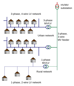
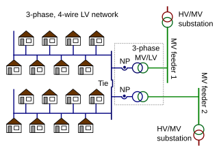
Electric power distribution is the final stage in the delivery of electricity. Electricity is carried from the transmission system to individual consumers. Distribution substations connect to the transmission system and lower the transmission voltage to medium voltage ranging between 2 kV and 33 kV with the use of transformers. Primary distribution lines carry this medium voltage power to distribution transformers located near the customer's premises. Distribution transformers again lower the voltage to the utilization voltage used by lighting, industrial equipment and household appliances. Often several customers are supplied from one transformer through secondary distribution lines. Commercial and residential customers are connected to the secondary distribution lines through service drops. Customers demanding a much larger amount of power may be connected directly to the primary distribution level or the subtransmission level.

<span class="mw-page-title-main">Power supply</span> Electronic device that converts or regulates electric energy and supplies it to a load

A power supply is an electrical device that supplies electric power to an electrical load. The main purpose of a power supply is to convert electric current from a source to the correct voltage, current, and frequency to power the load. As a result, power supplies are sometimes referred to as electric power converters. Some power supplies are separate standalone pieces of equipment, while others are built into the load appliances that they power. Examples of the latter include power supplies found in desktop computers and consumer electronics devices. Other functions that power supplies may perform include limiting the current drawn by the load to safe levels, shutting off the current in the event of an electrical fault, power conditioning to prevent electronic noise or voltage surges on the input from reaching the load, power-factor correction, and storing energy so it can continue to power the load in the event of a temporary interruption in the source power.

<span class="mw-page-title-main">Electrical substation</span> Part of an electrical transmission, and distribution system

A substation is a part of an electrical generation, transmission, and distribution system. Substations transform voltage from high to low, or the reverse, or perform any of several other important functions. Between the generating station and consumer, electric power may flow through several substations at different voltage levels. A substation may include transformers to change voltage levels between high transmission voltages and lower distribution voltages, or at the interconnection of two different transmission voltages. They are a common component of the infrastructure. There are 55,000 substations in the United States.

<span class="mw-page-title-main">Single-wire earth return</span> Supply energy using single wire with earth as return

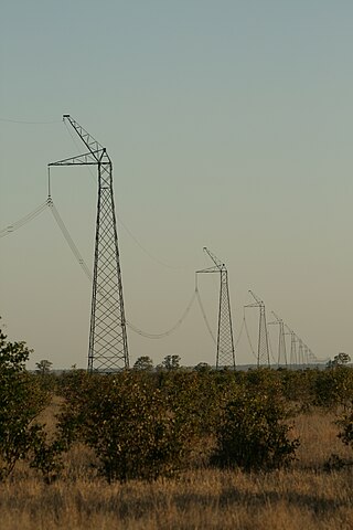
Single-wire earth return (SWER) or single-wire ground return is a single-wire transmission line which supplies single-phase electric power from an electrical grid to remote areas at lowest cost. The earth is used as the return path for the current, to avoid the need for a second wire to act as a return path.

In electrical engineering, particularly power engineering, voltage regulation is a measure of change in the voltage magnitude between the sending and receiving end of a component, such as a transmission or distribution line. Voltage regulation describes the ability of a system to provide near constant voltage over a wide range of load conditions. The term may refer to a passive property that results in more or less voltage drop under various load conditions, or to the active intervention with devices for the specific purpose of adjusting voltage.

<span class="mw-page-title-main">Autotransformer</span> Type of electrical transformer

In electrical engineering, an autotransformer is an electrical transformer with only one winding. The "auto" prefix refers to the single coil acting alone. In an autotransformer, portions of the same winding act as both the primary winding and secondary winding sides of the transformer. In contrast, an ordinary transformer has separate primary and secondary windings that are not connected by an electrically conductive path. between them.

The prospective short-circuit current (PSCC), available fault current, or short-circuit making current is the highest electric current which can exist in a particular electrical system under short-circuit conditions. It is determined by the voltage and impedance of the supply system. It is of the order of a few thousand amperes for a standard domestic mains electrical installation, but may be as low as a few milliamperes in a separated extra-low voltage (SELV) system or as high as hundreds of thousands of amps in large industrial power systems. The term is used in electrical engineering rather than electronics.

<span class="mw-page-title-main">Current transformer</span> Transformer used to scale alternating current, used as sensor for AC power

A current transformer (CT) is a type of transformer that is used to reduce or multiply an alternating current (AC). It produces a current in its secondary which is proportional to the current in its primary.

<span class="mw-page-title-main">Distribution transformer</span> Final stage in power distribution to users

A distribution transformer or service transformer is a transformer that provides a final voltage transformation in the electric power distribution system, stepping down the voltage used in the distribution lines to the level used by the customer. The invention of a practical efficient transformer made AC power distribution feasible; a system using distribution transformers was demonstrated as early as 1882.

<span class="mw-page-title-main">Recloser</span>

In electric power distribution, automatic circuit reclosers (ACRs) are a class of switchgear designed for use on overhead electricity distribution networks to detect and interrupt transient faults. Also known as reclosers or autoreclosers, ACRs are essentially rated circuit breakers with integrated current and voltage sensors and a protection relay, optimized for use as a protection asset. Commercial ACRs are governed by the IEC 62271-111/IEEE Std C37.60 and IEC 62271-200 standards. The three major classes of operating maximum voltage are 15.5 kV, 27 kV and 38 kV.

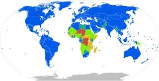
An earthing system or grounding system (US) connects specific parts of an electric power system with the ground, typically the Earth's conductive surface, for safety and functional purposes. The choice of earthing system can affect the safety and electromagnetic compatibility of the installation. Regulations for earthing systems vary among countries, though most follow the recommendations of the International Electrotechnical Commission (IEC). Regulations may identify special cases for earthing in mines, in patient care areas, or in hazardous areas of industrial plants.

<span class="mw-page-title-main">Extra-low voltage</span> Electrical standard designed to protect against electric shock

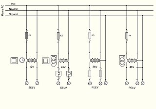
Extra-low voltage (ELV) is an electricity supply voltage and is a part of the low-voltage band in a range which carries a low risk of dangerous electrical shock. There are various standards that define extra-low voltage. The International Electrotechnical Commission (IEC) and the UK IET define an ELV device or circuit as one in which the electrical potential between two conductors or between an electrical conductor and earth (ground) does not exceed 120 volts (V) for ripple-free direct current (DC) or 50 VRMS for alternating current (AC).

<span class="mw-page-title-main">Spot network substation</span>

In electricity distribution networks, spot network substations are used in interconnected distribution networks. They have the secondary network with all supply transformers bussed together on the secondary side at one location. Spot networks are considered the most reliable and most flexible arrangement of connecting power to all types of loads. Switching can be done without interrupting the power to the loads.

A network protector is a type of electric protective device used in electricity distribution systems. The network protector automatically disconnect its associated distribution transformer from the secondary network when the power starts flowing in reverse direction. Network protectors are used on both spot networks and grid networks. The secondary grid system improves continuity of service for customers, since multiple sources are available to supply the load; a fault with any one supply is automatically isolated by the network protector and does not interrupt service from the other sources. Secondary grids are often used in downtown areas of cities where there are many customers in a small area.

<span class="mw-page-title-main">Electric power system</span> Network of electrical component deployed to generate, transmit & distribute electricity

An electric power system is a network of electrical components deployed to supply, transfer, and use electric power. An example of a power system is the electrical grid that provides power to homes and industries within an extended area. The electrical grid can be broadly divided into the generators that supply the power, the transmission system that carries the power from the generating centers to the load centers, and the distribution system that feeds the power to nearby homes and industries.

<span class="mw-page-title-main">Electrical grid</span> Interconnected network for delivering electricity from suppliers to consumers

An electrical grid is an interconnected network for electricity delivery from producers to consumers. Electrical grids consist of power stations, electrical substations to step voltage up or down, electric power transmission to carry power over long distances, and finally electric power distribution to customers. In that last step, voltage is stepped down again to the required service voltage. Power stations are typically built close to energy sources and far from densely populated areas. Electrical grids vary in size and can cover whole countries or continents. From small to large there are microgrids, wide area synchronous grids, and super grids.

References