An electric motor is a machine that converts electrical energy into mechanical energy. Most electric motors operate through the interaction between the motor's magnetic field and electric current in a wire winding to generate force in the form of torque applied on the motor's shaft. An electric generator is mechanically identical to an electric motor, but operates in reverse, converting mechanical energy into electrical energy.
In electricity generation, a generator is a device that converts motion-based power or fuel-based power into electric power for use in an external circuit. Sources of mechanical energy include steam turbines, gas turbines, water turbines, internal combustion engines, wind turbines and even hand cranks. The first electromagnetic generator, the Faraday disk, was invented in 1831 by British scientist Michael Faraday. Generators provide nearly all the power for electrical grids.

A flywheel is a mechanical device that uses the conservation of angular momentum to store rotational energy, a form of kinetic energy proportional to the product of its moment of inertia and the square of its rotational speed. In particular, assuming the flywheel's moment of inertia is constant then the stored (rotational) energy is directly associated with the square of its rotational speed.

An alternator is an electrical generator that converts mechanical energy to electrical energy in the form of alternating current. For reasons of cost and simplicity, most alternators use a rotating magnetic field with a stationary armature. Occasionally, a linear alternator or a rotating armature with a stationary magnetic field is used. In principle, any AC electrical generator can be called an alternator, but usually, the term refers to small rotating machines driven by automotive and other internal combustion engines.

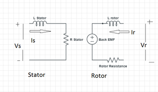
An induction motor or asynchronous motor is an AC electric motor in which the electric current in the rotor that produces torque is obtained by electromagnetic induction from the magnetic field of the stator winding. An induction motor therefore needs no electrical connections to the rotor. An induction motor's rotor can be either wound type or squirrel-cage type.

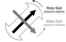
A synchronous electric motor is an AC electric motor in which, at steady state, the rotation of the shaft is synchronized with the frequency of the supply current; the rotation period is exactly equal to an integer number of AC cycles. Synchronous motors use electromagnets as the stator of the motor which create a magnetic field that rotates in time with the oscillations of the current. The rotor with permanent magnets or electromagnets turns in step with the stator field at the same rate and as a result, provides the second synchronized rotating magnet field. A synchronous motor is termed doubly fed if it uses independently-excited multiphase AC electromagnets for both rotor and stator.

A DC motor is an electrical motor that uses direct current (DC) to produce mechanical force. The most common types rely on magnetic forces produced by currents in the coils. Nearly all types of DC motors have some internal mechanism, either electromechanical or electronic, to periodically change the direction of current in part of the motor.

In electrical engineering, the armature is the winding of an electric machine which carries alternating current. The armature windings conduct AC even on DC machines, due to the commutator action or due to electronic commutation, as in brushless DC motors. The armature can be on either the rotor or the stator, depending on the type of electric machine.

In electrical engineering, a synchronous condenser is a DC-excited synchronous motor, whose shaft is not connected to anything but spins freely. Its purpose is not to convert electric power to mechanical power or vice versa, but to adjust conditions on the electric power transmission grid. Its field is controlled by a voltage regulator to either generate or absorb reactive power as needed to adjust the grid's voltage, or to improve power factor. The condenser’s installation and operation are identical to large electric motors and generators.

An AC motor is an electric motor driven by an alternating current (AC). The AC motor commonly consists of two basic parts, an outside stator having coils supplied with alternating current to produce a rotating magnetic field, and an inside rotor attached to the output shaft producing a second rotating magnetic field. The rotor magnetic field may be produced by permanent magnets, reluctance saliency, or DC or AC electrical windings.
An induction generator or asynchronous generator is a type of alternating current (AC) electrical generator that uses the principles of induction motors to produce electric power. Induction generators operate by mechanically turning their rotors faster than synchronous speed. A regular AC induction motor usually can be used as a generator, without any internal modifications. Because they can recover energy with relatively simple controls, induction generators are useful in applications such as mini hydro power plants, wind turbines, or in reducing high-pressure gas streams to lower pressure.

The rotor is a moving component of an electromagnetic system in the electric motor, electric generator, or alternator. Its rotation is due to the interaction between the windings and magnetic fields which produces a torque around the rotor's axis.
A brushed DC electric motor is an internally commutated electric motor designed to be run from a direct current power source and utilizing an electric brush for contact.

Ward Leonard control, also known as the Ward Leonard drive system, was a widely used DC motor speed control system introduced by Harry Ward Leonard in 1891. In the early 1900s, the control system of Ward Leonard was adopted by the U.S. Navy and also used in passenger lifts of large mines. It also provided a solution to a moving sidewalk at the Paris Exposition of 1900, where many others had failed to operate properly. It was applied to railway locomotives used in World War I, and was used in anti-aircraft radars in World War II. Connected to automatic anti-aircraft gun directors, the tracking motion in two dimensions had to be extremely smooth and precise. The MIT Radiation Laboratory selected Ward-Leonard to equip the famous radar SCR-584 in 1942. The Ward Leonard control system was widely used for elevators until thyristor drives became available in the 1980s, because it offered smooth speed control and consistent torque. Many Ward Leonard control systems and variations on them remain in use.
In electrical engineering, electric machine is a general term for machines using electromagnetic forces, such as electric motors, electric generators, and others. They are electromechanical energy converters: an electric motor converts electricity to mechanical power while an electric generator converts mechanical power to electricity. The moving parts in a machine can be rotating or linear. While transformers are occasionally called "static electric machines", since they do not have moving parts, generally they are not considered "machines", but as electrical devices "closely related" to the electrical machines.

In electromagnetism, excitation is the process of generating a magnetic field by means of an electric current.

A magneto is an electrical generator that uses permanent magnets to produce periodic pulses of alternating current. Unlike a dynamo, a magneto does not contain a commutator to produce direct current. It is categorized as a form of alternator, although it is usually considered distinct from most other alternators, which use field coils rather than permanent magnets.
An armature controlled DC motor is a direct current (DC) motor that uses a permanent magnet driven by the armature coils only.
A power system consists of a number of synchronous machines operating synchronously under all operating conditions. Under normal operating conditions, the relative position of the rotor axis and the resultant magnetic field axis is fixed. The angle between the two is known as the power angle, torque angle, or rotor angle. During any disturbance, the rotor decelerates or accelerates with respect to the synchronously rotating air gap magnetomotive force, creating relative motion. The equation describing the relative motion is known as the swing equation, which is a non-linear second order differential equation that describes the swing of the rotor of synchronous machine. The power exchange between the mechanical rotor and the electrical grid due to the rotor swing is called Inertial response.
The reactances of synchronous machines comprise a set of characteristic constants used in the theory of synchronous machines. Technically, these constants are specified in units of the electrical reactance (ohms), although they are typically expressed in the per-unit system and thus dimensionless. Since for practically all machines the resistance of the coils is negligibly small in comparison to the reactance, the latter can be used instead of (complex) electrical impedance, simplifying the calculations.