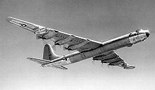
1871 PlanophoreA Farman MF.11, showing the classic Farman configuration with engine between tail boomsBuhl A-1 Autogyro, the first pusher autogyroThe post-WWII Convair B-36 was unusual in its size, era, number of engines, and combining both propeller and jet propulsion, with six radial piston and four jet enginesTypical of many UAVs, the General Atomics MQ-9 Reaper has a propeller at the extreme tailNAL Saras, with pushers mounted on pods on either side of the rear fuselage
The rubber-powered "Planophore", designed by Alphonse Pénaud in 1871, was an early successful model aircraft with a pusher propeller.
Many early aircraft (especially biplanes) were "pushers", including the Wright Flyer (1903), the Santos-Dumont 14-bis (1906), the Voisin-Farman I (1907), and the Curtiss Model D used by Eugene Ely for the first ship landing on January 18, 1911. Henri Farman's pusher Farman III and its successors were so influential in Britain that pushers in general became known as the "Farman type".[note 1] Other early pusher configurations were variations on this theme.
The classic "Farman" pusher had the propeller "mounted (just) behind the main lifting surface" with the engine fixed to the lower wing or between the wings, immediately forward of the propeller in a stub fuselage (that also contained the pilot) called a nacelle. The main difficulty with this type of pusher design was attaching the tail (empennage). This needed to be in the same general location as on a tractor aircraft, but its support structure had to avoid the propeller.
The earliest examples of pushers relied on a canard but this has serious aerodynamic implications that the early designers were unable to resolve. Typically, mounting the tail was done with a complex wire-braced framework that created a lot of drag. Well before the beginning of the First World War, this drag was recognized as just one of the factors that would ensure that a Farman-style pusher would have an inferior performance to an otherwise similar tractor type.
The U.S. Army banned pusher aircraft in late 1914 after several pilots died in crashes of aircraft of this type,[2] so from about 1912 onwards, the great majority of new U.S. landplane designs were tractor biplanes, with pushers of all types becoming regarded as old-fashioned on both sides of the Atlantic. However, new pusher designs continued to be designed right up to the armistice, such as the Vickers Vampire, although few entered service after 1916.[citation needed]
At least up to the end of 1916, however, pushers (such as the Airco DH.2 fighter) were still favored as gun-carrying aircraft by the British Royal Flying Corps, because a forward-firing gun could be used without being obstructed by the arc of the propeller. With the successful introduction of Fokker's mechanism for synchronizing the firing of a machine gun with the blades of a moving propeller,[3] followed quickly by the widespread adoption of synchronization gears by all the combatants in 1916 and 1917, the tractor configuration became almost universally favored, and pushers were reduced to the tiny minority of new aircraft designs that had a specific reason for using the arrangement.
Both the British and French continued to use pusher-configured bombers, though there was no clear preference either way until 1917. Such aircraft included (apart from the products of the Farman company) the Voisin bombers (3,200 built), the Vickers F.B.5 "Gunbus", and the Royal Aircraft Factory F.E.2; however, even these found themselves being shunted into training roles before disappearing entirely. Possibly the last fighter to use the Farman pusher configuration was the 1931 Vickers Type 161 COW gun fighter.
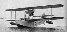
During the long eclipse of the configuration the use of pusher propellers continued in aircraft which derived a small benefit from the installation and could have been built as tractors. Biplane flying boats had for some time often been fitted with engines located above the fuselage to offer maximum clearance from the water, often driving pusher propellers to avoid spray and the hazards involved by keeping them well clear of the cockpit. The Supermarine Walrus was a late example of this layout.
The so-called push/pull layout, combining the tractor and pusher configurations—that is, with one or more propellers facing forward and one or more others facing back—was another idea that continues to be used from time to time as a means of reducing the asymmetric effects of an outboard engine failure, such as on the Farman F.222, but at the cost of a severely reduced efficiency on the rear propellers, which were often smaller and attached to lower-powered engines as a result.
By the late 1930s, the widespread adoption of all-metal stressed skin construction of aircraft meant, at least in theory, that the aerodynamic penalties that had limited the performance of pushers (and indeed any unconventional layout) were reduced; however, any improvement that boosts pusher performance also boosts the performance of conventional aircraft, and they remained a rarity in operational service—so the gap was narrowed but was closed entirely.
During World War II, experiments were conducted with pusher fighters by most of the major powers. Difficulties remained, particularly that a pilot having to bail out of a pusher was liable to pass through the propeller arc. This meant that of all the types concerned, only the relatively conventional Swedish SAAB 21 of 1943 went into series production. Other problems related to the aerodynamics of canard layouts, which had been used on most of the pushers, proved more difficult to resolve.[note 2] One of the world's first ejection seats was (per force) designed for this aircraft, which later re-emerged with a jet engine.
The largest pusher aircraft to fly was the Convair B-36 "Peacemaker" of 1946, which was also the largest bomber ever operated by the United States. It had six 3,800hp (2,800kW) 28-cylinder Pratt & Whitney Wasp Majorradial engines mounted in the wing, each driving a pusher propeller located behind the trailing edge of the wing, plus four jet engines.
Aero Dynamics Sparrow Hawk II
Although the vast majority of propeller-driven aircraft continue to use a tractor configuration, there has been in recent years something of a revival of interest in pusher designs: in light homebuilt aircraft such as Burt Rutan's canard designs since 1975, ultralights such as the Quad City Challenger (1983), flexwings, paramotors, powered parachutes, and autogyros. The configuration is also often used for unmanned aerial vehicles, due to requirements for a forward fuselage free of any engine interference.
Pusher aircraft have been built in many different configurations. In the vast majority of fixed-wing aircraft, the propeller or propellers are still located just behind the trailing edge of the "main lifting surface", or below the wing (paramotors) with the engine being located behind the crew position.
Gallaudet D-4 with pusher prop rotating around the rear fuselage
Conventional aircraft layout have a tail (empennage) for stabilization and control. The propeller may be close to the engine, as the usual direct drive:
The propeller may be located inside the tail, either cruciform or ducted fan (Marvelette).
The propeller may be located at the rear, behind a conventional tail (Bede BD-5).
The propeller may be located above the fuselage such as on many small flying boats (Lake Buccaneer)
Progenitor to a large number of canard pushers, the experimental Miles M.35 Libellula had its engine at the rear of the fuselage
In canard designs a smaller wing is sited forward of the aircraft's main wing. This class mainly uses a direct drive,[note 3] either single-engine axial propeller,[note 4] or twin engines with a symmetrical layout,[note 5] or an in line layout (push-pull) as the Rutan Voyager.
In tailless aircraft such as Lippisch Delta 1 and Westland-Hill Pterodactyl types I and IV, horizontal stabilizers at the rear of the aircraft are absent. Flying wings like the Northrop YB-35 are tailless aircraft without a distinct fuselage. In these installations, the engines are either mounted in nacelles or the fuselage on tailless aircraft, or buried in the wing on flying wings, driving propellers behind the trailing edge of the wing, often by extension shaft.
Voisin III bomber, the most numerous pusher design, with 3200 built
Other craft with pusher configurations run on flat surfaces, land, water, snow, or ice. Thrust is provided by propellers and ducted fans, located to the rear of the vehicle. These include:
Hovercraft, lifted by an air cushion, such as the 58-passenger SR.N6.
Aerosledges, also known as the aerosleigh, propeller-driven sledge, or propeller-driven snowmobile.
In aircraft
Advantages
The drive shaft of a pusher engine is in compression in normal operation,[5] which places less stress on it than being in tension in a tractor configuration. [dubious–discuss]
Practical requirements
Flexwing microlight with engine and propeller at the pilot's back
Placing the cockpit forward of the wing to balance the weight of the engine(s) aft improves visibility for the crew. In military aircraft, front armament could be used more easily on account of the gun not needing to synchronize itself with the propeller, although the risk that spent casings fly into the props at the back somewhat offset this advantage.[citation needed]
Aircraft where the engine is carried by, or very close to, the pilot (such as paramotors, powered parachutes, autogyros, and flexwing trikes) place the engine behind the pilot to minimize the danger to the pilot's arms and legs.[citation needed] These two factors mean that this configuration was widely used for early combat aircraft, and remains popular today among ultralight aircraft, unmanned aerial vehicles (UAVs), and radio-controlled airplanes.[citation needed]
Aerodynamics
A pusher may have a shorter fuselage and hence a reduction in both fuselage wetted area and weight.[6]
In contrast to tractor layout, a pusher propeller at the end of the fuselage is stabilizing.[7] A pusher needs less stabilizing vertical tail area[8] and hence presents less weathercock effect;[9] at takeoff roll, it is generally less sensitive to crosswind.[note 6][10][11]
When there is no tail within the slipstream, unlike a tractor, there is no rotating propwash around the fuselage inducing a side force to the fin. At takeoff, a canard pusher pilot does not have to apply rudder input to balance this moment.[12]
Efficiency can be gained by mounting a propeller behind the fuselage, because it re-energizes the boundary layer developed on the body, and reduces the form drag by keeping the flow attached to the fuselage. However, it is usually a minor gain compared to the airframe's detrimental effect on propeller efficiency.[8]
Wing profile drag may be reduced due to the absence of prop-wash over any section of the wing.[citation needed]
The engine is mounted behind the crew and passenger compartments, so fuel oil and coolant leaks will vent behind the aircraft, and any engine fire will be directed behind the aircraft. Similarly, propeller failure is less likely to directly endanger the crew.[citation needed]
A pusher ducted fan system offers a supplementary safety feature attributed to enclosing the rotating fan in the duct, therefore making it an attractive option for various advanced UAV configurations or for small/personal air vehicles or for aircraft models.[13]
Disadvantages
Structural and weight considerations
SAAB J 21 fighter, with the pusher propeller mounted between two fuselage booms
A pusher design with an empennage behind the propeller is structurally more complex than a similar tractor type. The increased weight and drag degrades performance compared with a similar tractor type. Modern aerodynamic knowledge and construction methods may reduce but never eliminate the difference. A remote or buried engine requires a drive shaft and associated bearings, supports, and torsional vibration control, and adds weight and complexity.[14][15]
Center of gravity and landing gear considerations
To maintain a safe center of gravity (CG) position, there is a limit to how far aft an engine can be installed.[16] The forward location of the crew may balance the engine weight and will help determine the CG. As the CG location must be kept within defined limits for safe operation load distribution must be evaluated before each flight.[17][note 7]
Due to a generally high thrust line needed for propeller ground clearance, negative (down) pitching moments, and in some cases the absence of prop-wash over the tail, a higher speed and a longer roll may be required for takeoff compared to tractor aircraft.[18][19][20] The Rutan answer to this problem is to lower the nose of the aircraft at rest such that the empty center of gravity is then ahead of the main wheels. In autogyros, a high thrust line results in a control hazard known as power push-over.
Aerodynamic considerations
The Supermarine Walrus pusher flying boat is a typical flying boat, with the engine mounted high to avoid spray; however, throttle changes then induce pitch changes.
Due to the generally-high thrust line to ensure ground clearance, a low-wing pusher layout may suffer power-change-induced pitch changes, also known as pitch/power coupling. Pusher seaplanes with especially high thrust lines and tailwheels may find the vertical tail masked from the airflow, severely reducing control at low speeds, such as when taxiing. The absence of prop-wash over the wing reduces the lift and increases takeoff roll length.[21] Pusher engines mounted on the wing may obstruct sections of the wing trailing edge, reducing the total width available for control surfaces such as flaps and ailerons. When a propeller is mounted in front of the tail, changes in engine power alter the airflow over the tail and can give strong pitch or yaw changes.
Propeller ground clearance and foreign object damage
Due to the pitch rotation at takeoff, the propeller diameter may have to be reduced (with a loss of efficiency[22]) or landing gear made longer[6] and heavier. Many pushers[note 8] have ventral fins or skids beneath the propeller to prevent the propeller from striking the ground, at an added cost in drag and weight.[citation needed] On tailless pushers such as the Rutan Long-EZ, the propeller arc is very close to the ground while flying nose-high during takeoff or landing. Objects on the ground kicked up by the wheels can pass through the propeller disc, causing damage or accelerated wear to the blades; in extreme cases, the blades may strike the ground.
When an airplane flies in icing conditions, ice can accumulate on the wings. If an airplane with wing-mounted pusher engines experiences icing, the props will ingest shredded chunks of ice, endangering the propeller blades and parts of the airframe that can be struck by ice violently redirected by the props. In early pusher combat aircraft, spent ammunition casings caused similar problems, and devices for collecting them had to be devised.
Propeller efficiency and noise
The propeller passes through the fuselage wake, wing wake, and other flight surface downwashes—moving asymmetrically through a disk of irregular airspeed. This reduces propeller efficiency and causes vibration inducing structural propeller fatigue[note 9] and noise.
Prop efficiency is usually at least 2–5% less and in some cases more than 15% less than an equivalent tractor installation.[23] Full-scale wind tunnel investigation of the canard Rutan VariEze showed a propeller efficiency of 0.75 compared to 0.85 for a tractor configuration, a loss of 12%.[24] Pusher props are noisy,[14] and cabin noise may be higher than tractor equivalent (Cessna XMC vs Cessna 152).[25] Propeller noise may increase because the engine exhaust flows through the props. This effect may be particularly pronounced when using turboprop engines due to the large volume of exhaust they produce.[8]
Engine cooling and exhaust
Power-plant cooling design is more complex in pusher engines than for the tractor configuration, where the propeller forces air over the engine or radiator. Some aviation engines have experienced cooling problems when used as pushers.[25] To counter this, auxiliary fans may be installed, adding additional weight. The engine of a pusher exhausts forward of the propeller, and in this case, the exhaust may contribute to corrosion or other damage to the propeller. This is usually minimal, and may be mainly visible in the form of soot stains on the blades.
Safety
Propeller
Piaggio P.180 Avanti with engines mounted on the wing trailing edge, away from passengers, allowing safer boarding.
In case of propeller/tail proximity, a blade break can hit the tail or produce destructive vibrations, leading to a loss of control.[26]
Crew members risk striking the propeller while attempting to bail out of a single-engined airplane with a pusher prop.[27] At least one early ejector seat was designed specifically to counter this risk.[citation needed] Some modern light aircraft include a parachute system that saves the entire aircraft, thus averting the need to bail out.[citation needed]
Engine
Engine location in the pusher configuration might endanger the aircraft's occupants in a crash or crash-landing in which engine momentum projects through the cabin. For example, with the engine placed directly behind the cabin, during a nose-on impact, the engine momentum may carry the engine through the firewall and cabin, and might injure some cabin occupants.[note 10]
Aircraft loading
Spinning propellers are always a hazard on ground working, such as loading or embarking the airplane. The tractor configuration leaves the rear of the plane as relatively safe working area, while a pusher is dangerous to approach from behind, while a spinning propeller may suck in things and people nearby in front of it with fatal results to both the plane and the people sucked in.[undue weight?–discuss] Even more hazardous are unloading operations, especially mid-air, such as dropping supplies on parachute or skydiving operations, which are next to impossible with a pusher configuration airplane, especially if propellers are mounted on fuselage or sponsons.[citation needed]
↑ In the case of the Cozy IV, a side-by-side four-seater, an absent copilot must be balanced with 20 kg (40 lb) in the nose of the aircraft (Cafe Aircraft Performance Report)
↑ Guttman, Jon (10 September 2009). Pusher Aces of World War 1. Illustrated by Harry Dempsey. Oxford, England: Osprey Publishing. pp.6–7. ISBN9781846034176.
↑ Gunston, Bill (10 May 2004). The Cambridge Aerospace Dictionary. Cambridge University Press. p.480. ISBN978-0521841405.
1 2 Raymer, Daniel P. (1989). Aircraft Design: A Conceptual Approach. Reston, Virginia: American Institute of Aeronautics & Astronautics. pp.222–223. ISBN9781600869112.
↑ Hoerner, Sighard (1975). "XIII Directional characteristics of aeroplanes: IV Influence of Propulsion". Fluid-Dynamic Lift: Practical Information on Aerodynamic and Hydrodynamic Lift. Vol.76. p.17. Bibcode:1975STIA...7632167H.{{cite book}}: |journal= ignored (help)
↑ Roskam, Jan (1999). Airplane Design Part II: Preliminary Configuration Design and Integration of the Propulsion System. Vol.2. Lawrence, Kansas: Design, Analysis and Research Corporation. p.132. ISBN9781884885433.
↑ Stinton, Darrol (1983). "Propeller Effects". The Design of the Aeroplane. St Albans, Hertfordshire, England: Granada Publishing. pp.304–307. ISBN9780632018772.
1 2 Garrison, Peter (29 June 2009). "Technicalities". Flying. Archived from the original on 29 March 2012. Retrieved 12 October 2011.
↑ Hassenaur, Donald P. (1 January 1996). "Propeller Drive Systems and Torsional Vibration". Alternative Engines. Vol.1. compiled by Mick Myal. Phoenix, Arizona: Fiesta Publishing. pp.167–172. ISBN9780964361324.
↑ Seeley, Brien; Stephens, C.J. "Cozy Mk IV"(PDF). Aircraft Performance Reports. The CAFE Board. CAFE Foundation. Archived from the original(PDF) on 27 October 2010.
↑ Berven, Lester H. BD-5 Flight Test Program Report (Technical report). Bede Aircraft Corporation. Archived from the original on 19 November 2011 – via Journal of the Society Of Experimental Test Pilots.
↑ Abzug, Malcolm J.; Larrabee, E. Eugene (2002). Airplane Stability and Control: A History of the Technologies that Made Aviation Possible. Cambridge University Press. p.257. doi:10.1017/CBO9780511607141. ISBN9780511607141.
1 2 Visschedijk, Johan; Tilborg, Walter van; Smith, Karl (14 December 2003). "Cessna XMC". 1000aircraftphotos.com. Archived from the original on 30 January 2008.
↑ Grinvalds Orion crash in 1985, Experimental magazine n°2, March 1986, pages 20-24, Extrait du Rapport d'expertise: "La cause initiale de l'accident la plus probable est la rupture du mécanisme de commande de pas d'une pale de l'hélice. Cette rupture a a engendré des vibrations importantes de la partie arrière de l'avion... ruptures structurales... privant les pilotes des commandes de vol de profondeur et de direction". Failure of the pitch command system of one blade, important propeller vibrations, structural break, loss of pitch and yaw control
↑ Brown, Eric (1961). "Chapter 10". Wings on My Sleeve. London, England: Weidenfeld & Nicolson. pp.150–151. ISBN9780753822098.
Sources
Abzug, Malcolm J.; Larrabee, E. Eugene (2005). Airplane Stability and Control: A History of the Technologies That Made Aviation Possible. Cambridge Aerospace Series 14 (2nded.). Cambridge, UK: Cambridge University Press. ISBN978-0521809924.
Gunston, Bill (2004). The Cambridge Aerospace Dictionary Cambridge. Cambridge University Press. p.480. ISBN978-0521841405.
Guttman, Jon (2009). Pusher Aces of World War 1. Osprey Aircraft of the Aces 88. Oxford, UK: Osprey. ISBN978-1846034176.
Hoerner, Gihard F.; Borst, Henry V. (1985). Fluid-Dynamic Lift - Practical Information on Aerodynamic and Hydrodynamic Lift. Brick Town, New Jersey: Mrs. Liselotte Hoerner. LCCN75-17441.
Raymer, Daniel P. (1992). Aircraft Design: A Conceptual Approach. AIAA Education Series. Washington, DC: American Institute of Aeronautics and Astronautics. ISBN978-0930403515.
Stinton, Daroll (1983). The Design of the Aeroplane. Oxford, UK: BSP Professional Books. ISBN978-0632018772.
This page is based on this Wikipedia article Text is available under the CC BY-SA 4.0 license; additional terms may apply. Images, videos and audio are available under their respective licenses.