Fundamental considerations
Design of a radio receiver must consider several fundamental criteria to produce a practical result. The main criteria are gain, selectivity, sensitivity, and stability. The receiver must contain a detector to recover the information initially impressed on the radio carrier signal, a process called modulation. [1]
Gain is required because the signal intercepted by an antenna will have a very low power level, on the order of picowatts or femtowatts. To produce an audible signal in a pair of headphones requires this signal to be amplified a trillion-fold or more. The magnitudes of the required gain are so great that the logarithmic unit decibel is preferred - a gain of 1 trillion times the power is 120 decibels, which is a value achieved by many common receivers. Gain is provided by one or more amplifier stages in a receiver design; some of the gain is applied at the radio-frequency part of the system, and the rest at the frequencies used by the recovered information (audio, video, or data signals).
Selectivity is the ability to "tune in" to just one station of the many that may be transmitting at any given time. An adjustable bandpass filter is a typical stage of a receiver. A receiver may include several stages of bandpass filters to provide sufficient selectivity. Additionally, the receiver design must provide immunity from spurious signals that may be generated within the receiver that would interfere with the desired signal. Broadcasting transmitters in any given area are assigned frequencies so that receivers can properly select the desired transmission; this is a key factor limiting the number of transmitting stations that can operate in a given area.
Sensitivity is the ability to recover the signal from the background noise. Noise is generated in the path between transmitter and receiver, but is also significantly generated in the receiver's own circuits. Inherently, any circuit above absolute zero generates some random noise that adds to the desired signals. In some cases, atmospheric noise is far greater than that produced in the receiver's own circuits, but in some designs, measures such as cryogenic cooling are applied to some stages of the receiver, to prevent signals from being obscured by thermal noise. A very good receiver design may have a noise figure of only a few times the theoretical minimum for the operating temperature and desired signal bandwidth. The objective is to produce a signal-to-noise ratio of the recovered signal sufficient for the intended purpose. This ratio is also often expressed in decibels. A signal-to-noise ratio of 10 dB (signal 10 times as powerful as noise) might be usable for voice communications by experienced operators, but a receiver intended for high-fidelity music reproduction might require 50 dB or higher signal-to-noise ratio.
Stability is required in at least two senses. Frequency stability; the receiver must stay "tuned" to the incoming radio signal and must not "drift" with time or temperature. Additionally, the great magnitude of gain generated must be carefully controlled so that spurious emissions are not produced within the receiver. These would lead to distortion of the recovered information, or, at worst, may radiate signals that interfere with other receivers.
The detector stage recovers the information from the radio-frequency signal, and produces the sound, video, or data that was impressed on the carrier wave initially. Detectors may be as simple as an "envelope" detector for amplitude modulation, or may be more complex circuits for more recently developed techniques such as frequency-hopping spread spectrum.
While not fundamental to a receiver, automatic gain control is a great convenience to the user, since it automatically compensates for changing received signal levels or different levels produced by different transmitters.
Many different approaches and fundamental receiver "block diagrams" have developed to address these several, sometimes contradictory, factors. Once these technical objectives have been achieved, the remaining design process is still complicated by considerations of economics, patent rights, and even fashion.
An electronic oscillator is an electronic circuit that produces a periodic, oscillating or alternating current (AC) signal, usually a sine wave, square wave or a triangle wave, powered by a direct current (DC) source. Oscillators are found in many electronic devices, such as radio receivers, television sets, radio and television broadcast transmitters, computers, computer peripherals, cellphones, radar, and many other devices.

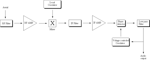
A superheterodyne receiver, often shortened to superhet, is a type of radio receiver that uses frequency mixing to convert a received signal to a fixed intermediate frequency (IF) which can be more conveniently processed than the original carrier frequency. It was invented by French radio engineer and radio manufacturer Lucien Lévy. Virtually all modern radio receivers use the superheterodyne principle.

A heterodyne is a signal frequency that is created by combining or mixing two other frequencies using a signal processing technique called heterodyning, which was invented by Canadian inventor-engineer Reginald Fessenden. Heterodyning is used to shift signals from one frequency range into another, and is also involved in the processes of modulation and demodulation. The two input frequencies are combined in a nonlinear signal-processing device such as a vacuum tube, transistor, or diode, usually called a mixer.

In communications and electronic engineering, an intermediate frequency (IF) is a frequency to which a carrier wave is shifted as an intermediate step in transmission or reception. The intermediate frequency is created by mixing the carrier signal with a local oscillator signal in a process called heterodyning, resulting in a signal at the difference or beat frequency. Intermediate frequencies are used in superheterodyne radio receivers, in which an incoming signal is shifted to an IF for amplification before final detection is done.
A tetrode is a vacuum tube having four active electrodes. The four electrodes in order from the centre are: a thermionic cathode, first and second grids, and a plate. There are several varieties of tetrodes, the most common being the screen-grid tube and the beam tetrode. In screen-grid tubes and beam tetrodes, the first grid is the control grid and the second grid is the screen grid. In other tetrodes one of the grids is a control grid, while the other may have a variety of functions.

A regenerative circuit is an amplifier circuit that employs positive feedback. Some of the output of the amplifying device is applied back to its input to add to the input signal, increasing the amplification. One example is the Schmitt trigger, but the most common use of the term is in RF amplifiers, and especially regenerative receivers, to greatly increase the gain of a single amplifier stage.
A variable frequency oscillator (VFO) in electronics is an oscillator whose frequency can be tuned over some range. It is a necessary component in any tunable radio transmitter and in receivers that works by the superheterodyne principle. The oscillator controls the frequency to which the apparatus is tuned.
A tuned radio frequency receiver is a type of radio receiver that is composed of one or more tuned radio frequency (RF) amplifier stages followed by a detector (demodulator) circuit to extract the audio signal and usually an audio frequency amplifier. This type of receiver was popular in the 1920s. Early examples could be tedious to operate because when tuning in a station each stage had to be individually adjusted to the station's frequency, but later models had ganged tuning, the tuning mechanisms of all stages being linked together, and operated by just one control knob. By the mid 1930s, it was replaced by the superheterodyne receiver patented by Edwin Armstrong.

In radio communications, a radio receiver, also known as a receiver, a wireless, or simply a radio, is an electronic device that receives radio waves and converts the information carried by them to a usable form. It is used with an antenna. The antenna intercepts radio waves and converts them to tiny alternating currents which are applied to the receiver, and the receiver extracts the desired information. The receiver uses electronic filters to separate the desired radio frequency signal from all the other signals picked up by the antenna, an electronic amplifier to increase the power of the signal for further processing, and finally recovers the desired information through demodulation.

In a radio receiver, a beat frequency oscillator or BFO is a dedicated oscillator used to create an audio frequency signal from Morse code radiotelegraphy (CW) transmissions to make them audible. The signal from the BFO is mixed with the received signal to create a heterodyne or beat frequency which is heard as a tone in the speaker. BFOs are also used to demodulate single-sideband (SSB) signals, making them intelligible, by essentially restoring the carrier that was suppressed at the transmitter. BFOs are sometimes included in communications receivers designed for short wave listeners; they are almost always found in communication receivers for amateur radio, which often receive CW and SSB signals.

A Gunn diode, also known as a transferred electron device (TED), is a form of diode, a two-terminal semiconductor electronic component, with negative differential resistance, used in high-frequency electronics. It is based on the "Gunn effect" discovered in 1962 by physicist J. B. Gunn. Its main uses are in electronic oscillators to generate microwaves, in applications such as radar speed guns, microwave relay data link transmitters, and automatic door openers.
In electronics, a local oscillator (LO) is an electronic oscillator used with a mixer to change the frequency of a signal. This frequency conversion process, also called heterodyning, produces the sum and difference frequencies from the frequency of the local oscillator and frequency of the input signal. Processing a signal at a fixed frequency gives a radio receiver improved performance. In many receivers, the function of local oscillator and mixer is combined in one stage called a "converter" - this reduces the space, cost, and power consumption by combining both functions into one active device.
In a radio receiver circuit, the RF front end, short for radio frequency front end, is a generic term for all the circuitry between a receiver's antenna input up to and including the mixer stage. It consists of all the components in the receiver that process the signal at the original incoming radio frequency (RF), before it is converted to a lower intermediate frequency (IF). In microwave and satellite receivers it is often called the low-noise block downconverter (LNB) and is often located at the antenna, so that the signal from the antenna can be transferred to the rest of the receiver at the more easily handled intermediate frequency.
A direct-conversion receiver (DCR), also known as homodyne, synchrodyne, or zero-IF receiver, is a radio receiver design that demodulates the incoming radio signal using synchronous detection driven by a local oscillator whose frequency is identical to, or very close to the carrier frequency of the intended signal. This is in contrast to the standard superheterodyne receiver where this is accomplished only after an initial conversion to an intermediate frequency.

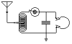
The Neutrodyne radio receiver, invented in 1922 by Louis Hazeltine, was a particular type of tuned radio frequency (TRF) receiver, in which the instability-causing inter-electrode capacitance of the triode RF tubes is cancelled out or "neutralized" to prevent parasitic oscillations which caused "squealing" or "howling" noises in the speakers of early radio sets. In most designs, a small extra winding on each of the RF amplifiers' tuned anode coils was used to generate a small antiphase signal, which could be adjusted by special variable trim capacitors to cancel out the stray signal coupled to the grid via plate-to-grid capacitance. The Neutrodyne circuit was popular in radio receivers until the 1930s, when it was superseded by the superheterodyne receiver.
A radio transmitter or just transmitter is an electronic device which produces radio waves with an antenna. Radio waves are electromagnetic waves with frequencies between about 30 Hz and 300 GHz. The transmitter itself generates a radio frequency alternating current, which is applied to the antenna. When excited by this alternating current, the antenna radiates radio waves. Transmitters are necessary parts of all systems that use radio: radio and television broadcasting, cell phones, wireless networks, radar, two way radios like walkie talkies, radio navigation systems like GPS, remote entry systems, among numerous other uses.

In radio, a detector is a device or circuit that extracts information from a modulated radio frequency current or voltage. The term dates from the first three decades of radio (1888-1918). Unlike modern radio stations which transmit sound on an uninterrupted carrier wave, early radio stations transmitted information by radiotelegraphy. The transmitter was switched on and off to produce long or short periods of radio waves, spelling out text messages in Morse code. Therefore, early radio receivers did not have to demodulate the radio signal, but just distinguish between the presence or absence of a radio signal, to reproduce the Morse code "dots" and "dashes". The device that performed this function in the receiver circuit was called a detector. A variety of different detector devices, such as the coherer, electrolytic detector, magnetic detector and the crystal detector, were used during the wireless telegraphy era until superseded by vacuum tube technology.

A reflex radio receiver, occasionally called a reflectional receiver, is a radio receiver design in which the same amplifier is used to amplify the high-frequency radio signal (RF) and low-frequency audio (sound) signal (AF). It was first invented in 1914 by German scientists Wilhelm Schloemilch and Otto von Bronk, and rediscovered and extended to multiple tubes in 1917 by Marius Latour and William H. Priess. The radio signal from the antenna and tuned circuit passes through an amplifier, is demodulated in a detector which extracts the audio signal from the radio carrier, and the resulting audio signal passes again through the same amplifier for audio amplification before being applied to the earphone or loudspeaker. The reason for using the amplifier for "double duty" was to reduce the number of active devices, vacuum tubes or transistors, required in the circuit, to reduce the cost. The economical reflex circuit was used in inexpensive vacuum tube radios in the 1920s, and was revived again in simple portable tube radios in the 1930s.

The autodyne circuit was an improvement to radio signal amplification using the De Forest Audion vacuum tube amplifier. By allowing the tube to oscillate at a frequency slightly different from the desired signal, the sensitivity over other receivers was greatly improved. The autodyne circuit was invented by Edwin Howard Armstrong of Columbia University, New York, NY. He inserted a tuned circuit in the output circuit of the Audion vacuum tube amplifier. By adjusting the tuning of this tuned circuit, Armstrong was able to dramatically increase the gain of the Audion amplifier. Further increase in tuning resulted in the Audion amplifier reaching self-oscillation.

In electronics, a plate detector is a vacuum tube circuit in which an amplifying tube having a control grid is operated in a non-linear region of its grid voltage versus plate current transfer characteristic, usually near plate current cutoff, to demodulate amplitude modulated carrier signal. This differs from the grid leak detector, which utilizes the non-linearity of the grid voltage versus grid current characteristic for demodulation. It also differs from the diode detector, which is a two-terminal device.