By extension, the term continuous wave also refers to an early method of radiotransmission in which a sinusoidal carrier wave is switched on and off. This is more precisely called interrupted continuous wave (ICW).[2]Information is carried in the varying duration of the on and off periods of the signal, for example by Morse code in early radio. In early wireless telegraphy radio transmission, CW waves were also known as "undamped waves", to distinguish this method from damped wave signals produced by earlier spark gap type transmitters.
Radio
Transmissions before CW
Very early radio transmitters used a spark gap to produce radio-frequency oscillations in the transmitting antenna. The signals produced by these spark-gap transmitters consisted of strings of brief pulses of sinusoidal radio frequency oscillations which died out rapidly to zero, called damped waves. The disadvantage of damped waves was that their energy was spread over an extremely wide band of frequencies; they had wide bandwidth. As a result, they produced electromagnetic interference (RFI) that spread over the transmissions of stations at other frequencies.
This motivated efforts to produce radio frequency oscillations that decayed more slowly; had less damping. There is a direct relation between the rate of decay (the reciprocal of the time constant) of a damped wave and its bandwidth; the longer the damped waves take to decay toward zero, the narrower the frequency band the radio signal occupies, so the less it interferes with other transmissions. As more transmitters began crowding the radio spectrum, reducing the frequency spacing between transmissions, government regulations began to limit the maximum damping or "decrement" a radio transmitter could have. Manufacturers produced spark transmitters which generated long "ringing" waves with minimal damping.
Transition to CW
It was realized that the ideal radio wave for radiotelegraphic communication would be a sine wave with zero damping, a continuous wave. An unbroken continuous sine wave theoretically has no bandwidth; all its energy is concentrated at a single frequency, so it doesn't interfere with transmissions on other frequencies. Continuous waves could not be produced with an electric spark, but were achieved with the vacuum tubeelectronic oscillator, invented around 1913 by Edwin Armstrong and Alexander Meissner. After World War I, transmitters capable of producing continuous wave, the Alexanderson alternator and vacuum tubeoscillators, became widely available.
Damped wave spark transmitters were replaced by continuous wave vacuum tube transmitters around 1920, and damped wave transmissions were finally outlawed in 1934.
In order to transmit information, the continuous wave must be turned off and on with a telegraph key to produce the different length pulses, "dots" and "dashes", that spell out text messages in Morse code, so a "continuous wave" radiotelegraphy signal consists of pulses of sine waves with a constant amplitude interspersed with gaps of no signal.
In on-off carrier keying, if the carrier wave is turned on or off abruptly, communications theory can show that the bandwidth will be large; if the carrier turns on and off more gradually, the bandwidth will be smaller. The bandwidth of an on-off keyed signal is related to the data transmission rate as: where is the necessary bandwidth in hertz, is the keying rate in signal changes per second (baud rate), and is a constant related to the expected radio propagation conditions; K=1 is difficult for a human ear to decode, K=3 or K=5 is used when fading or multipath propagation is expected.[3]
The spurious noise emitted by a transmitter which abruptly switches a carrier on and off is called key clicks. The noise occurs in the part of the signal bandwidth further above and below the carrier than required for normal, less abrupt switching. The solution to the problem for CW is to make the transition between on and off to be more gradual, making the edges of pulses soft, appearing more rounded, or to use other modulation methods (e.g. phase modulation). Certain types of power amplifiers used in transmission may aggravate the effect of key clicks.
Persistence of radio telegraphy
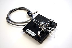
A commercially manufactured paddle for use with electronic keyer to generate Morse code
Early radio transmitters could not be modulated to transmit speech, and so CW radio telegraphy was the only form of communication available. CW still remains a viable form of radio communication many years after voice transmission was perfected, because simple, robust transmitters can be used, and because its signals are the simplest of the forms of modulation able to penetrate interference. The low bandwidth of the code signal, due in part to low information transmission rate, allows very selective filters to be used in the receiver, which block out much of the radio noise that would otherwise reduce the intelligibility of the signal.
Continuous-wave radio was called radiotelegraphy because like the telegraph, it worked by means of a simple switch to transmit Morse code. However, instead of controlling the electricity in a cross-country wire, the switch controlled the power sent to a radio transmitter. This mode is still in common use by amateur radio operators due to its narrow bandwidth and high signal-to-noise ratio compared to other modes of communication.
In military communications and amateur radio the terms "CW" and "Morse code" are often used interchangeably, despite the distinctions between the two. Aside from radio signals, Morse code may be sent using direct current in wires, sound, or light, for example. For radio signals, a carrier wave is keyed on and off to represent the dots and dashes of the code elements. The carrier's amplitude and frequency remain constant during each code element. At the receiver, the received signal is mixed with a heterodyne signal from a BFO (beat frequency oscillator) to change the radio frequency impulses to sound. Almost all commercial traffic has now ceased operation using Morse, but it is still used by amateur radio operators. Non-directional beacons (NDB) and VHF omnidirectional radio range (VOR) used in air navigation use Morse to transmit their identifier.
Radar
Morse code is all but extinct outside the amateur service, so in non-amateur contexts the term CW usually refers to a continuous-wave radar system, as opposed to one transmitting short pulses. Some monostatic (single antenna) CW radars transmit and receive a single (non-swept) frequency, often using the transmitted signal as the local oscillator for the return; examples include police speed radars and microwave-type motion detectors and automatic door openers. This type of radar is effectively "blinded" by its own transmitted signal to stationary targets; they must move toward or away from the radar quickly enough to create a Doppler shift sufficient to allow the radar to isolate the outbound and return signal frequencies. This kind of CW radar can measure range rate but not range (distance).
Other CW radars linearly or pseudo-randomly "chirp" (frequency modulate) their transmitters rapidly enough to avoid self-interference with returns from objects beyond some minimum distance; this kind of radar can detect and range static targets. This approach is commonly used in radar altimeters, in meteorology and in oceanic and atmospheric research. The landing radar on the Apollo Lunar Module combined both CW radar types.
CW bistatic radars use physically separate transmit and receive antennas to lessen the self-interference problems inherent in monostatic CW radars.
Laser physics
In laser physics and engineering, "continuous wave" or "CW" refers to a laser that produces a continuous output beam, sometimes referred to as "free-running," as opposed to a q-switched, gain-switched or modelocked laser, which has a pulsed output beam.
This page is based on this Wikipedia article Text is available under the CC BY-SA 4.0 license; additional terms may apply. Images, videos and audio are available under their respective licenses.