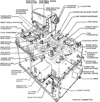
Figure 1: The Ford Mk 1 Ballistic Computer. The name "rangekeeper" began to become inadequate to describe the increasingly complicated functions of rangekeeper. The Mk 1 Ballistic Computer was the first rangekeeper that was referred to as a computer. Note the three pistol grips in the foreground, which are the firing keys of the main guns. The left sounds an alarm that the guns are about to fire, the center fires in automatic mode (Range Keeper controlled), and right is manual firing.
Rangekeepers were electromechanical fire control computers used primarily during the early part of the 20th century. They were sophisticated analog computers whose development reached its zenith following World War II, specifically the Computer Mk 47 in the Mk 68 Gun Fire Control system. During World War II, rangekeepers directed gunfire on land, sea, and in the air. While rangekeepers were widely deployed, the most sophisticated rangekeepers were mounted on warships to direct the fire of long-range guns.[1]
These warship-based computing devices needed to be sophisticated because the problem of calculating gun angles in a naval engagement is very complex. In a naval engagement, both the ship firing the gun and the target are moving with respect to each other. In addition, the ship firing its gun is not a stable platform because it will roll, pitch, and yaw due to wave action, ship change of direction, and board firing. The rangekeeper also performed the required ballistics calculations associated with firing a gun. This article focuses on US Navy shipboard rangekeepers, but the basic principles of operation are applicable to all rangekeepers regardless of where they were deployed.
Function
A rangekeeper is defined as an analog fire control system that performed three functions: [2]
Target tracking
The rangekeeper continuously computed the current target bearing. This is a difficult task because both the target and the ship firing (generally referred to as "own ship") are moving. This requires knowing the target's range, course, and speed accurately. It also requires accurately knowing the own ship's course and speed.
Target position prediction
When a gun is fired, it takes time for the projectile to arrive at the target. The rangekeeper must predict where the target will be at the time of projectile arrival. This is the point at which the guns are aimed.
Gunfire correction
Directing the fire of a long-range weapon to deliver a projectile to a specific location requires many calculations. The projectile point of impact is a function of many variables, including: gun azimuth, gun elevation, wind speed and direction, air resistance, gravity, latitude, gun/sight parallax, barrel wear, powder load, and projectile type.
History
Manual fire control
The early history of naval fire control was dominated by the engagement of targets within visual range (also referred to as direct fire). In fact, most naval engagements before 1800 were conducted at ranges of 20 to 50 yards (20 to 50m).[3] Even during the American Civil War, the famous engagement between the USSMonitor and the CSSVirginia was often conducted at less than 100 yards (90m) range. [4] With time, naval guns became larger and had greater range. At first, the guns were aimed using the technique of artillery spotting. Artillery spotting involved firing a gun at the target, observing the projectile's point of impact (fall of shot), and correcting the aim based on where the shell was observed to land, which became more and more difficult as the range of the gun increased.[3][5]
Predecessor fire control tools and systems
Between the American Civil War and 1905, numerous small improvements were made in fire control, such as telescopic sights and optical rangefinders. There were also procedural improvements, like the use of plotting boards to manually predict the position of a ship during an engagement. Around 1905, mechanical fire control aids began to become available, such as the Dreyer Table, Dumaresq (which was also part of the Dreyer Table), and Argo Clock, but these devices took a number of years to become widely deployed.[6][7] These devices were early forms of rangekeepers.
The issue of directing long-range gunfire came into sharp focus during World War I with the Battle of Jutland. While the British were thought by some to have the finest fire control system in the world at that time, during the Battle of Jutland only 3% of their shots actually struck their targets. At that time, the British primarily used a manual fire control system. The one British ship in the battle that had a mechanical fire control system turned in the best shooting results.[8] This experience contributed to rangekeepers becoming standard issue.[9]
Power drives and Remote Power Control (RPC)
The US Navy's first deployment of a rangekeeper was on the USSTexas in 1916. Because of the limitations of the technology at that time, the initial rangekeepers were crude. During World War I, the rangekeepers could generate the necessary angles automatically, but sailors had to manually follow the directions of the rangekeepers (a task called "pointer following" or "follow the pointer"). Pointer following could be accurate, but the crews tended to make inadvertent errors when they became fatigued during extended battles.[10] During World War II, servomechanisms (called "power drives" in the U.S. Navy and RPC in the Royal Navy) were developed that allowed the guns to automatically steer to the rangekeeper's commands with no manual intervention. The Mk. 1 and Mk. 1A computers contained approximately 20 servomechanisms, mostly position servos, to minimize torque load on the computing mechanisms. The Royal Navy first installed RPC, experimentally, aboard HMS Champion in 1928. In the 1930s RPC was used for naval searchlight control and during WW2 it was progressively installed on pom-pom mounts and directors, 4-inch, 4.5-inch and 5.25-inch gun mounts.[11][12]
During their long service life, rangekeepers were updated often as technology advanced, and by World War II they were a critical part of an integrated fire control system. The incorporation of radar into the fire control system early in World War II provided ships with the ability to conduct effective gunfire operations at long range in poor weather and at night.[13]
Service in World War II
During World War II, rangekeeper capabilities were expanded to the extent that the name "rangekeeper" was deemed to be inadequate. The term "computer," which had been reserved for human calculators, came to be applied to the rangekeeper equipment. After World War II, digital computers began to replace rangekeepers. However, components of the analog rangekeeper system continued in service with the US Navy until the 1990s.[14]
The performance of these analog computers was impressive. The battleshipUSSNorth Carolina during a 1945 test was able to maintain an accurate firing solution[15] on a target during a series of high-speed turns.[16] It is a major advantage for a warship to be able to maneuver while engaging a target.
Night naval engagements at long range became feasible when radar data could be input to the rangekeeper. The effectiveness of this combination was demonstrated in November 1942 at the Third Battle of Savo Island when the USSWashington engaged the JapanesebattlecruiserKirishima at a range of 8,400 yards (7.7km) at night. The Kirishima was set aflame, suffered a number of explosions, and was scuttled by her crew. She had been hit by nine 16-inch (410mm) rounds out of 75 fired (12% hit rate).[3] The wreck of the Kirishima was discovered in 1992 and showed that the entire bow section of the ship was missing.[17] The Japanese during World War II did not develop radar or automated fire control to the level of the US Navy and were at a significant disadvantage.[18] The Royal Navy began to introduce gyroscopic stabilization of their director gunsights in World War One and by the start of World War Two all warships fitted with director control had gyroscopically controlled gunsights.[19]
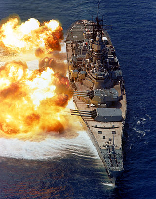
The last combat action for the analog rangekeepers, at least for the US Navy, was in the 1991 Persian Gulf War[14] when the rangekeepers on the Iowa-classbattleships directed their last rounds in combat.
Construction
Rangekeepers were very large, and the ship designs needed to make provisions to accommodate them. For example, the Ford Mk 1A Computer weighed 3,150 pounds (1,430kg)[20] The Mk. 1/1A's mechanism support plates, some an inch (25mm) thick, were made of aluminum alloy, but nevertheless, the computer is very heavy. On at least one refloated museum ship, the destroyer USSCassin Young (now in Boston), the computer and Stable Element more than likely still are below decks, because they are so difficult to remove.
The rangekeepers required a large number of electrical signal cables for synchro data transmission links over which they received information from the various sensors (e.g. gun director, pitometer, rangefinder, gyrocompass) and sent commands to the guns.
These computers also had to be formidably rugged, partly to withstand the shocks created by firing the ship's own guns, and also to withstand the effects of hostile enemy hits to other parts of the ship. They not only needed to continue functioning, but also stay accurate.
The Ford Mark 1/1A mechanism was mounted into a pair of approximately cubical large castings with very wide openings, the latter covered by gasketed castings. Individual mechanisms were mounted onto thick aluminum-alloy plates, and along with interconnecting shafts, were progressively installed into the housing. Progressive assembly meant that future access to much of the computer required progressive disassembly.
The Mk 47 computer was a radical improvement in accessibility over the Mk 1/1A. It was more akin to a tall, wide storage cabinet in shape, with most or all dials on the front vertical surface. Its mechanism was built in six sections, each mounted on very heavy-duty pull-out slides. Behind the panel were typically a horizontal and a vertical mounting plate, arranged in a tee.
Mechanisms
The problem of rangekeeping
Long-range gunnery is a complex combination of art, science, and mathematics. There are numerous factors that affect the ultimate placement of a projectile and many of these factors are difficult to model accurately. As such, the accuracy of battleship guns was ≈1% of range (sometimes better, sometimes worse). Shell-to-shell repeatability was ≈0.4% of range.[16]
Accurate long-range gunnery requires that a number of factors be taken into account:
Coriolis effect: Because the Earth is rotating, there is an apparent force acting on the projectile.
Internal ballistics: Guns do wear, and this aging must be taken into account by keeping an accurate count of the number of projectiles sent through the barrel (this count is reset to zero after the installation of a new liner). There are also shot-to-shot variations due to barrel temperature and interference between guns firing simultaneously.
External ballistics: Different projectiles have different ballistic characteristics. Also, air conditions have an effect as well (temperature, wind, air pressure).
Parallax correction: In general, the position of the gun and target spotting equipment (radar, mounted on the gun director, pelorus, etc) are in different locations on a ship. This creates a parallax error for which corrections must be made.
The calculations to predict and compensate for all these factors are complicated, frequent and error-prone when done by hand. Part of the complexity came from the amount of information that must be integrated from many different sources. For example, information from the following sensors, calculators, and visual aids must be integrated to generate a solution:
Rangefinders: Optical devices for determining the range to a target.
Pitometer Logs: These devices provided an accurate measurement of the own ship's speed.
Range clocks: These devices provided a prediction of the target's range at the time of projectile impact if the gun was fired now. This function could be considered "range keeping".
Angle clocks: This device provided a prediction of the target's bearing at the time of projectile impact if the gun was fired now.
Plotting board: A map of the gunnery platform and target that allowed predictions to be made as to the future position of a target. (The compartment ("room") where the Mk.1 and Mk.1A computers was located was called "Plot" for historical reasons.)
Various slide rules: These devices performed the various calculations required to determine the required gun azimuth and elevation.
Meteorological sensors: Temperature, wind speed, and humidity all have an effect on the ballistics of a projectile. U.S. Navy rangekeepers and analog computers did not consider different wind speeds at differing altitudes.
To increase speed and reduce errors, the military felt a dire need to automate these calculations. To illustrate the complexity, Table 1 lists the types of input for the Ford Mk 1 Rangekeeper (ca 1931).[3]
Table 1: Manual Inputs Into Pre-WWII Rangekeeper
Variable
Data Source
Range
Phoned from range finder
Own ship course
Gyrocompass repeater
Own ship speed
Pitometer log
Target course
Initial estimates for rate control
Target speed
Initial estimates for rate control
Target bearing
Automatically from director
Spotting data
Spotter, by telephone
However, even with all this data, the rangekeeper's position predictions were not infallible. The rangekeeper's prediction characteristics could be used against it. For example, many captains under long-range gun attack would make violent maneuvers to "chase salvos" or "steer for the fall of shot," i.e., maneuver to the position of the last salvo splashes. Because the rangekeepers are constantly predicting new positions for the target, it was unlikely that subsequent salvos would strike the position of the previous salvo.[21][full citation needed] Practical rangekeepers had to assume that targets were moving in a straight-line path at a constant speed, to keep complexity within acceptable limits. A sonar rangekeeper was built to track a target circling at a constant radius of turn, but that function was disabled.[citation needed]
General technique
The data were transmitted by rotating shafts. These were mounted in ball-bearing brackets fastened to the support plates. Most corners were at right angles, facilitated by miter gears in 1:1 ratio. The Mk. 47, which was modularized into six sections on heavy-duty slides, connected the sections together with shafts in the back of the cabinet. Shrewd design meant that the data carried by these shafts required no manual zeroing or alignment; only their movement mattered. The aided-tracking output from an integrator roller is one such example. When the section was slid back into normal position, the shaft couplings mated as soon as the shafts rotated.[citation needed]
Common mechanisms in the Mk. 1/1A included many miter-gear differentials, a group of four 3-D cams, some disk-ball-roller integrators, and servo motors with their associated mechanism; all of these had bulky shapes. However, most of the computing mechanisms were thin stacks of wide plates of various shapes and functions. A given mechanism might be an inch (25mm) thick, possibly less, and more than a few were maybe 14 inches (36cm) across. Space was at a premium, but for precision calculations, more width permitted a greater total range of movement to compensate for slight inaccuracies, stemming from looseness in sliding parts.
The Mk. 47 was a hybrid, doing some computing electrically, and the rest mechanically. It had gears and shafts, differentials, and totally enclosed disk-ball-roller integrators. However, it had no mechanical multipliers or resolvers ("component solvers"); these functions were performed electronically, with multiplication carried out using precision potentiometers.
In the Mk. 1/1A, however, excepting the electrical drive servos, all computing was mechanical.[22]:Chapter 2
The implementation methods used in analog computers were many and varied. The fire control equations implemented during World War II on analog rangekeepers are the same equations implemented later on digital computers. The key difference is that the rangekeepers solved the equations mechanically. While mathematical functions are not often implemented mechanically today, mechanical methods exist to implement all the common mathematical operations. Some examples include:
Differential gears, usually referred to by technicians simply as "differentials", were often used to perform addition and subtraction operations. The Mk. 1A contained approximately 160 of them. The history of this gearing for computing dates to antiquity (see Antikythera mechanism).
Gear ratios were very extensively used to multiply a value by a constant.
Multiplication of two variables
The Mk. 1 and Mk.1A computer multipliers were based on the geometry of similar triangles.
Sine and cosine generation (polar-to-rectangular coordinate conversion)
These mechanisms would be called resolvers, today; they were called "component solvers" in the mechanical era. In most instances, they resolved an angle and magnitude (radius) into sine and cosine components, with a mechanism consisting of two perpendicular Scotch yokes. A variable crankpin radius handled the magnitude of the vector in question.
The integrators had rotating discs and a full-width roller mounted in a hinged casting, pulled down toward the disc by two strong springs. Twin balls permitted free movement of the radius input with the disk stopped, something done at least daily for static tests. Integrators were made with discs of 3, 4 and 5inch (7.6, 10 and 12.5cm) diameters, the larger being more accurate. Ford Instrument Company integrators had a clever mechanism for minimizing wear when the ball-carrier carriage was in one position for extended periods.
Component integrators
Component integrators were essentially Ventosa integrators, all enclosed. Think of a traditional heavy-ball computer mouse and its pickoff rollers at right angles to each other. Underneath the ball is a roller that turns to rotate the mouse ball. However, the shaft of that roller can be set to any angle you want. In the Mk. 1/1A, a rate-control correction (keeping the sights on target) rotated the ball, and the two pickoff rollers at the sides distributed the movement appropriately according to angle. That angle depended upon the geometry of the moment, such as which way the target was heading.
Differentiation was performed by using an integrator in a feedback loop.
Functions of one variable
Rangekeepers used a number of cams to generate function values. Many face cams (flat discs with wide spiral grooves) were used in both rangekeepers. For surface fire control (the Mk. 8 Range Keeper), a single flat cam was sufficient to define ballistics.
Functions of two variables
In the Mk. 1 and Mk 1A computers, four three-dimensional cams were needed. These used cylindrical coordinates for their inputs, one being the rotation of the cam, and the other being the linear position of the ball follower. The radial displacement of the follower yielded the output.
The four cams in the Mk. 1/1A computer provided mechanical time fuse setting, time of flight (this time is from firing to bursting at or near the target), time of flight divided by predicted range, and superelevation combined with vertical parallax correction. (Superelevation is essentially the amount the gun barrel needs to be raised to compensate for gravity drop.)
The Mk.1 and Mk.1A computers were electromechanical, and many of their mechanical calculations required drive movements of precise speeds. They used reversible two-phase capacitor-run induction motors with tungsten contacts. These were stabilized primarily by rotary magnetic drag (eddy-current) slip clutches, similar to classical rotating-magnet speedometers, but with a much higher torque. One part of the drag was geared to the motor, and the other was constrained by a fairly stiff spring. This spring offset the null position of the contacts by an amount proportional to motor speed, thus providing velocity feedback. Flywheels mounted on the motor shafts, but coupled by magnetic drags, prevented contact chatter when the motor was at rest. Unfortunately, the flywheels must also have slowed down the servos somewhat. A more elaborate scheme, which placed a rather large flywheel and differential between the motor and the magnetic drag, eliminated velocity error for critical data, such as gun orders.
The Mk. 1 and Mk. 1A computer integrator discs required a particularly elaborate system to provide constant and precise drive speeds. They used a motor with its speed regulated by a clock escapement, cam-operated contacts, and a jeweled-bearing spur-gear differential. Although the speed oscillated slightly, the total inertia made it effectively a constant-speed motor. At each tick, contacts switched on motor power, then the motor opened the contacts again. It was in effect slow pulse-width modulation of motor power according to load. When running, the computer had a unique sound as motor power was switched on and off at each tick—dozens of gear meshes inside the cast-metal computer housing spread out the ticking into a "chunk-chunk" sound.
Assembly
A detailed description of how to dismantle and reassemble the system was contained in the two-volume Navy Ordnance Pamphlet OP 1140 with several hundred pages and several hundred photographs.[22] When reassembling, shaft connections between mechanisms had to be loosened and the mechanisms mechanically moved so that an output of one mechanism was at the same numerical setting (such as zero) as the input to the other. Fortunately these computers were especially well-made, and very reliable.[citation needed]
Related targeting systems
During WWII, all the major warring powers developed rangekeepers to different levels. [10] Rangekeepers were only one member of a class of electromechanical computers used for fire control during World War II. Related analog computing hardware used by the United States included:
US submarines used the TDC to compute torpedo launch angles. This device also had a rangekeeping function that was referred to as "position keeping." This was the only submarine-based fire control computer during World War II that performed target tracking. Because space within a submarine hull is limited, the TDC designers overcame significant packaging challenges in order to mount the TDC within the allocated volume.
↑ Technically, it would be more accurate to use the term "rifle" for long-range ship-board cannon. However, the term "gun" is commonly used and that nomenclature is maintained here.
↑ The increasing range of the guns also forced ships to create very high observation points from which optical rangefinders and artillery spotters could see the battle. The need to spot artillery shells was one of the compelling reasons behind the development of naval aviation and early aircraft were used to spot the naval gunfire points of impact. In some cases, ships launched manned observation balloons as a way to artillery spot. Even today, artillery spotting is an important part of directing gunfire, though today the spotting is often done by unmanned aerial vehicles. For example, during Desert Storm, UAVs spotted fire for the Iowa-class battleships involved in shore bombardment.
↑ Mindell, David (2002). Between Human and Machine. Baltimore: Johns Hopkins. pp.25–28. ISBN0-8018-8057-2.
↑ The reasons were for this slow deployment are complex. As in most bureaucratic environments, institutional inertia and the revolutionary nature of the change required caused the major navies to move slow in adopting the technology.
↑ Mindell, David (2002). Between Human and Machine. Baltimore: Johns Hopkins. pp.20–21. ISBN0-8018-8057-2.
↑ The British fleet's performance at Jutland has been a subject of much analysis and there were many contributing factors. When compared to the long-range gunnery performance by the US Navy and Kriegsmarine, the British gunnery performance at Jutland is not that poor. In fact, long-range gunnery is notorious for having a low hit percentage. For example, during exercises in 1930 and 1931, US battleships had hit percentages in the 4-6% range (Jurens).
↑ The degree of updating varied by country. For example, the US Navy used servomechanisms to automatically steer their guns in both azimuth and elevation. The Germans used servomechanisms to steer their guns only in elevation, and the British began to introduce Remote Power Control in elevation and deflection of 4-inch, 4.5-inch and 5.25-inch guns in 1942, according to Naval Weapons of WW2, by Campbell. For example HMSAnson's 5.25-inch guns had been upgraded to full RPC in time for her Pacific deployment.
↑ The rangekeeper in this exercise maintained a firing solution that was accurate within a few hundred yards (or meters), which is within the range needed for an effective rocking salvo. The rocking salvo was used by the US Navy to get the final corrections needed to hit the target.
↑ Mindell, David (2002). Between Human and Machine. Baltimore: Johns Hopkins. pp.262–263. ISBN0-8018-8057-2.
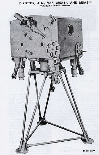
↑ Appendix one, Classification of Director Instruments, see external links.
↑ "Ballistic Computer". Destroyer Escort Central. USS Francis M. Robinson (DE-220) Association, 2000. 2003. Archived from the original on 2006-05-31. Retrieved 2006-09-26.
↑ Mindell, David (2002). Between Human and Machine. Baltimore: Johns Hopkins. p.254. ISBN0-8018-8057-2.
Bibliography
Brooks, John (2004). "Re: Questions on the Effectiveness of U.S. Navy Battleship Gunnery (W.I., 41 no. 1 (2004): 54)". Warship International. XLI (3): 260–262. ISSN0043-0374.
Brooks, John (2006). "Re: Questions on the Effectiveness of U.S. Navy Battleship Gunnery, Part II". Warship International. XLIII (1): 43–46. ISSN0043-0374.
Brooks, John (2005). "Re: Questions on the Effectiveness of U.S. Navy Battleship Gunnery, Part III". Warship International. XLII (3): 264–266. ISSN0043-0374.
Campbell, John (1985). Naval Weapons of World War Two. Naval Institute Press. ISBN0-87021-459-4.
Fairfield, A.P. (1921). Naval Ordnance. The Lord Baltimore Press.
Frieden, David R. (1985). Principles of Naval Weapons Systems. Naval Institute Press. ISBN0-87021-537-X.
Friedman, Norman (2008). Naval Firepower: Battleship Guns and Gunnery in the Dreadnought Era. Seaforth. ISBN978-1-84415-701-3.
Pollen, Antony (1980). The Great Gunnery Scandal - The Mystery of Jutland. Collins. ISBN0-00-216298-9.
Wright, Christopher C. (2004). "Questions on the Effectiveness of U.S. Navy Battleship Gunnery: Notes on the Origin of U.S. Navy Gun Fire Control System Range Keepers". Warship International. XLI (1): 55–78. ISSN0043-0374.
Wright, Christopher C. (2004). "Questions on the Effectiveness of U.S. Navy Battleship Gunnery: Notes on the Origins of U.S. Navy Gun Fire Control System Range Keepers, Part II". Warship International. XLI (3): 288–311. ISSN0043-0374.
Wright, Christopher C. (2005). "Questions on the Effectiveness of U.S. Navy Battleship Gunnery: Notes on the Origins of U.S. Navy Gun Fire Control System Range Keepers, Part III". Warship International. XLII (1): 61–105. ISSN0043-0374.
The Montana-class battleships were planned as successors of the Iowa class for the United States Navy, to be slower but larger, better armored, and with superior firepower. Five were approved for construction during World War II, but changes in wartime building priorities resulted in their cancellation in favor of continuing production of Essex-class aircraft carriers and Iowa-class battleships before any Montana-class keels were laid.
The Kerrison Predictor was one of the first fully automated anti-aircraft fire-control systems. It was used to automate the aiming of the British Army's Bofors 40 mm guns and provide accurate lead calculations through simple inputs on three main handwheels.
The 16"/50 caliber Mark 7 – United States Naval Gun is the main armament of the Iowa-class battleships and was the planned main armament of the cancelled Montana-class battleship.
A fire-control system (FCS) is a number of components working together, usually a gun data computer, a director, and radar, which is designed to assist a ranged weapon system to target, track, and hit a target. It performs the same task as a human gunner firing a weapon, but attempts to do so faster and more accurately.
Naval artillery is artillery mounted on a warship, originally used only for naval warfare and then subsequently used for more specialized roles in surface warfare such as naval gunfire support (NGFS) and anti-aircraft warfare (AAW) engagements. The term generally refers to tube-launched projectile-firing weapons and excludes self-propelled projectiles such as torpedoes, rockets, and missiles and those simply dropped overboard such as depth charges and naval mines.
In ballistics, the elevation is the angle between the horizontal plane and the axial direction of the barrel of a gun, mortar or heavy artillery. Originally, elevation was a linear measure of how high the gunners had to physically lift the muzzle of a gun up from the gun carriage to compensate for projectile drop and hit targets at a certain distance.
Gun laying is the process of aiming an artillery piece or turret, such as a gun, howitzer, or mortar, on land, in air, or at sea, against surface or aerial targets. It may be laying for direct fire, where the gun is aimed similarly to a rifle, or indirect fire, where firing data is calculated and applied to the sights. The term includes automated aiming using, for example, radar-derived target data and computer-controlled guns.
The Mark 12 5"/38 caliber gun was a United States dual-purpose naval gun, but also installed in single-purpose mounts on a handful of ships. The 38 caliber barrel was a mid-length compromise between the previous United States standard 5"/51 low-angle gun and 5"/25 anti-aircraft gun. United States naval gun terminology indicates the gun fired a projectile 5 inches (127 mm) in diameter, and the barrel was 38 calibers long. The increased barrel length provided greatly improved performance in both anti-aircraft and anti-surface roles compared to the 5"/25 gun. However, except for the barrel length and the use of semi-fixed ammunition, the 5"/38 gun was derived from the 5"/25 gun. Both weapons had power ramming, which enabled rapid fire at high angles against aircraft. The 5"/38 entered service on USS Farragut, commissioned in 1934, the first new destroyer design since the last Clemson was built in 1922. The base ring mount, which improved the effective rate of fire, entered service on USS Porter, commissioned in 1936.
High Angle Control System (HACS) was a British anti-aircraft fire-control system employed by the Royal Navy from 1931 and used widely during World War II. HACS calculated the necessary deflection required to place an explosive shell in the location of a target flying at a known height, bearing and speed.
In naval gunnery, when long-range guns became available, an enemy ship would move some distance after the shells were fired. It became necessary to figure out where the enemy ship, the target, was going to be when the shells arrived. The process of keeping track of where the ship was likely to be was called rangekeeping, because the distance to the target—the range—was a very important factor in aiming the guns accurately. As time passed, train, the direction to the target, also became part of rangekeeping, but tradition kept the term alive.
The Mark 1, and later the Mark 1A, Fire Control Computer was a component of the Mark 37 Gun Fire Control System deployed by the United States Navy during World War II and up to 1991 and possibly later. It was originally developed by Hannibal C. Ford of the Ford Instrument Company. and William Newell. It was used on a variety of ships, ranging from destroyers to battleships. The Mark 37 system used tachymetric target motion prediction to compute a fire control solution. It contained a target simulator which was updated by further target tracking until it matched.
The Iowa-class battleships are the most heavily armed gunships the United States Navy has ever put to sea, due to the continual development of their onboard weaponry. The first Iowa-class ship was laid down in June 1940; in their World War II configuration, each of the Iowa-class battleships had a main battery of 16-inch (406 mm) guns that could hit targets nearly 20 statute miles (32 km) away with a variety of artillery shells designed for anti-ship or bombardment work. The secondary battery of 5-inch (127 mm) guns could hit targets nearly 9 statute miles (14 km) away with solid projectiles or proximity fuzed shells, and was effective in an anti-aircraft role as well. Each of the four battleships carried a wide array of 20 mm and 40 mm anti-aircraft guns for defense against enemy aircraft.
A director, also called an auxiliary predictor, is a mechanical or electronic computer that continuously calculates trigonometric firing solutions for use against a moving target, and transmits targeting data to direct the weapon firing crew.
The QF 5.25-inch Mark I gun was the heaviest dual-purpose gun used by the Royal Navy during the Second World War. Although considered less than completely successful, it saw extensive service. 267 guns were built.
Ship gun fire-control systems (GFCS) are analogue fire-control systems that were used aboard naval warships prior to modern electronic computerized systems, to control targeting of guns against surface ships, aircraft, and shore targets, with either optical or radar sighting. Most US ships that are destroyers or larger employed gun fire-control systems for 5-inch (127 mm) and larger guns, up to battleships, such as Iowa class.
The Admiralty Fire Control Table (A.F.C.T.) was an electromechanical analogue computer fire-control system that calculated the correct elevation and deflection of the main armament of a Royal Navy cruiser or battleship, so that the shells fired would strike a surface target. The AFCT MK 1 was fitted to HMS Nelson and Rodney in the early 1920s, while the battleships Warspite, Valiant, and Queen Elizabeth, and the battlecruiser Renown, received Mk VII tables in the late 1930s. Battleships of the King George V class received a Mk IX table, while Vanguard received the final variant, the Mk X. The AFCT was the successor to the Dreyer tables, developed by Captain Frederic Charles Dreyer, and the Argo Clock, developed by Arthur Pollen, and received developmental input from both men.
"Pom-Pom" director was a director for British anti-aircraft guns on British warships of the 1930s into the Second World War.
Gyro rate unit refers to a fire-control computer developed by the Royal Navy of the United Kingdom in 1937, and which was used extensively on British warships in World War II. In the 1930s the Royal Navy began to investigate the possibility of combining gyroscopes with optical sights to directly and accurately measure target aircraft speed and direction and began development of the GRU in 1937. A gyroscope was attached, via mechanical linkage, to an optical monocular sight to form the gyro rate unit or GRU.
The Torpedo Data Computer (TDC) was an early electromechanical analog computer used for torpedo fire-control on American submarines during World War II. Britain, Germany, and Japan also developed automated torpedo fire control equipment, but none were as advanced as the US Navy's TDC, as it was able to automatically track the target rather than simply offering an instantaneous firing solution. This unique capability of the TDC set the standard for submarine torpedo fire control during World War II.
This page is based on this Wikipedia article Text is available under the CC BY-SA 4.0 license; additional terms may apply. Images, videos and audio are available under their respective licenses.