"Rolling mill" redirects here. For mills that use rollers to crush grain or stone, see roller mill.
Rolling schematic viewRolling visualization
In metalworking, rolling is a metal forming process in which metal stock is passed through one or more pairs of rolls to reduce the thickness, to make the thickness uniform, and/or to impart a desired mechanical property. The concept is similar to the rolling of dough. Rolling is classified according to the temperature of the metal rolled. If the temperature of the metal is above its recrystallization temperature, then the process is known as hot rolling. If the temperature of the metal is below its recrystallization temperature, the process is known as cold rolling. In terms of usage, hot rolling processes more tonnage than any other manufacturing process, and cold rolling processes the most tonnage out of all cold working processes.[1][2]Roll stands holding pairs of rolls are grouped together into rolling mills that can quickly process metal, typically steel, into products such as structural steel (I-beams, angle stock, channel stock), bar stock, and rails. Most steel mills have rolling mill divisions that convert the semi-finished casting products into finished products.
The invention of the rolling mill may be attributed to Leonardo da Vinci in his drawings.[3][failed verification] Earliest rolling mills were slitting mills, which were introduced from what is now Belgium to England in 1590. These passed flat bars between rolls to form a plate of iron, which was then passed between grooved rolls (slitters) to produce rods of iron.[4] The first experiments at rolling iron for tinplate took place about 1670. In 1697, Major John Hanbury erected a mill at Pontypool to roll "Pontypool plates" – blackplate. Later this began to be rerolled and tinned to make tinplate. The earlier production of plate iron in Europe had been in forges, not rolling mills.
The slitting mill was adapted to producing hoops (for barrels) and iron with a half-round or other sections by means that were the subject of two patents of c. 1679.
Some of the earliest literature on rolling mills can be traced back to the Swedish engineer Christopher Polhem in his Patriotista Testamente of 1761, where he mentions rolling mills for both plate and bar iron.[5] He also explains how rolling mills can save on time and labor because a rolling mill can produce 10 to 20 or more bars at the same time.
A patent was granted to Thomas Blockley of England in 1759 for the polishing and rolling of metals. Another patent was granted in 1766 to Richard Ford of England for the first tandem mill.[6] A tandem mill is one in which the metal is rolled in successive stands; Ford's tandem mill was for hot rolling of wire rods.
Other metals
This section needs expansion. You can help by adding to it. (December 2009)
Rolling mills for lead seem to have existed by the late 17th century. Copper and brass were also rolled by the late 18th century.
Modern rolling
Until well into the eighteenth century, rolling mills derived their power from water wheels. The first recorded use of a steam engine directly driving a mill is attributed to John Wilkinson's Bradley Works where, in 1786, a Boulton and Watt engine was coupled to a slitting and rolling mill. The use of steam engines considerably enhanced the production capabilities of the mills, until this form of power was displaced by electric motors soon after 1900.[7]
Modern rolling practice can be attributed to the pioneering efforts of Henry Cort of Funtley Iron Mills, near Fareham in Hampshire, England. In 1783, a patent number was issued to Henry Cort for his use of grooved rolls for rolling iron bars.[8] With this new design, mills were able to produce 15 times more output per day than with a hammer.[9] Although Cort was not the first to use grooved rolls, he was the first to combine the use of many of the best features of various ironmaking and shaping processes known at the time. Thus modern writers have called him "father of modern rolling".
The first rail rolling mill was established by John Birkenshaw at Bedlington Ironworks in Northumberland, England, in 1820, where he produced fish-bellied wrought iron rails in lengths of 15 to 18 feet.[9] With the advancement of technology in rolling mills, the size of rolling mills grew rapidly along with the size of the products being rolled. One example of this was at The Great Exhibition in London in 1851, where a plate 20 feet long, 3 1⁄2 feet wide, and 7/16 of an inch thick, and weighing 1,125 pounds, was exhibited by the Consett Iron Company.[9] Further evolution of the rolling mill came with the introduction of three-high mills in 1853 used for rolling heavy sections.
If these products came from a continuous casting operation, the products are usually fed directly into the rolling mills at the proper temperature. In smaller operations, the material starts at room temperature and must be heated. This is done in a gas- or oil-fired soaking pit for larger workpieces; for smaller workpieces, induction heating is used. As the material is worked, the temperature must be monitored to make sure it remains above the recrystallization temperature.
Soaking pits used to heat steel ingots before rolling
To maintain a safety factor a finishing temperature is defined above the recrystallization temperature; this is usually 50 to 100°C (122 to 212°F) above the recrystallization temperature. If the temperature does drop below this temperature the material must be re-heated prior to additional hot rolling.[10]
A coil of hot-rolled steel
Hot-rolled metals generally have little directionality in their mechanical properties or deformation-induced residual stresses. However, in certain instances non-metallic inclusions will impart some directionality and workpieces less than 20mm (0.79in) thick often have some directional properties. Non-uniform cooling will induce a lot of residual stresses, which usually occurs in shapes that have a non-uniform cross-section, such as I-beams. While the finished product is of good quality, the surface is covered in mill scale, which is an oxide that forms at high temperatures. It is usually removed via pickling or the smooth clean surface (SCS) process, which reveals a smooth surface.[11] Dimensional tolerances are usually 2 to 5% of the overall dimension.[12]
Hot-rolled mild steel seems to have a wider tolerance for the level of included carbon than does cold-rolled steel, and is, therefore, more difficult for a blacksmith to use.
Hot rolling is used mainly to produce sheet metal or simple cross-sections, such as rail tracks.
Shape rolling design
Rolling mills are often divided into roughing, intermediate and finishing rolling cages. During shape rolling, an initial billet (round or square) with edge of diameter typically ranging between 100 and 140mm is continuously deformed to produce a certain finished product with smaller cross section dimension and geometry. Starting from a given billet, different sequences can be adopted to produce a certain final product. However, since each rolling mill is significantly expensive (up to 2 million euros), a typical requirement is to reduce the number of rolling passes. Different approaches have been achieved, including empirical knowledge, employment of numerical models, and Artificial Intelligence techniques. Lambiase et al.[13][14] validated a finite element model (FE) for predicting the final shape of a rolled bar in round-flat pass. One of the major concerns when designing rolling mills is to reduce the number of passes. A possible solution to such requirements is the slit pass, also called split pass, which divides an incoming bar in two or more subparts, thus virtually increasing the cross section reduction ratio per pass as reported by Lambiase.[15] Another solution for reducing the number of passes in rolling mills is the employment of automated systems for Roll Pass Design as that proposed by Lambiase and Langella.[16] subsequently, Lambiase further developed an Automated System based on Artificial Intelligence and particularly an integrated system including an inferential engine based on Genetic Algorithms a knowledge database based on an Artificial Neural Network trained by a parametric Finite element model and to optimize and automatically design rolling mills.[17]
Sheets of tin being cold-rolled in South Wales during World WarI
Cold rolling occurs with the metal below its recrystallization temperature (usually at room temperature), which increases the strength via strain hardening up to 20%. It also improves the surface finish and holds tighter tolerances. Commonly cold-rolled products include sheets, strips, bars, and rods; these products are usually smaller than the same products that are hot rolled. Because of the smaller size of the workpieces and their greater strength, as compared to hot rolled stock, four-high or cluster mills are used.[2] Cold rolling cannot reduce the thickness of a workpiece as much as hot rolling in a single pass.
Cold-rolled sheets and strips come in various conditions: full-hard, half-hard, quarter-hard, and skin-rolled. Full-hard rolling reduces the thickness by 50%, while the others involve less of a reduction. Cold rolled steel is then annealed to induce ductility in the cold rolled steel which is simply known as a Cold Rolled and Close Annealed. Skin-rolling, also known as a skin-pass, involves the least amount of reduction: 0.5–1%. It is used to produce a smooth surface, a uniform thickness, and reduce the yield point phenomenon (by preventing Lüders bands from forming in later processing). It locks dislocations at the surface and thereby reduces the possibility of formation of Lüders bands. To avoid the formation of Lüders bands it is necessary to create substantial density of unpinned dislocations in ferrite matrix. It is also used to break up the spangles in galvanized steel. Skin-rolled stock is usually used in subsequent cold-working processes where good ductility is required.
Other shapes can be cold-rolled if the cross-section is relatively uniform and the transverse dimension is relatively small. Cold rolling shapes requires a series of shaping operations, usually along the lines of sizing, breakdown, roughing, semi-roughing, semi-finishing, and finishing.
If processed by a blacksmith, the smoother, more consistent, and lower levels of carbon encapsulated in the steel makes it easier to process, but at the cost of being more expensive.[18]
Roll forming, roll bending or plate rolling is a continuous bending operation in which a long strip of metal (typically coiled steel) is passed through consecutive sets of rolls, or stands, each performing only an incremental part of the bend, until the desired cross-section profile is obtained. Roll forming is ideal for producing parts with long lengths or in large quantities. There are three main processes: 4 rollers, 3 rollers and 2 rollers, each of which has as different advantages according to the desired specifications of the output plate.
Flat rolling
Flat rolling is the most basic form of rolling with the starting and ending material having a rectangular cross-section. The material is fed in between two rollers, called working rolls, that rotate in opposite directions. The gap between the two rolls is less than the thickness of the starting material, which causes it to deform. The decrease in material thickness causes the material to elongate. The friction at the interface between the material and the rolls causes the material to be pushed through. The amount of deformation possible in a single pass is limited by the friction between the rolls; if the change in thickness is too great the rolls just slip over the material and do not draw it in.[1] The final product is either sheet or plate, with the former being less than 6mm (0.24in) thick and the latter greater than; however, heavy plates tend to be formed using a press, which is termed forging, rather than rolling.[citation needed]
Often the rolls are heated to assist in the workability of the metal. Lubrication is often used to keep the workpiece from sticking to the rolls.[citation needed] To fine-tune the process, the speed of the rolls and the temperature of the rollers are adjusted.[20]
For thin sheet metal with a thickness less than 200μm (0.0079in),[citation needed] the rolling is done in a cluster mill because the small thickness requires a small diameter rolls.[10] To reduce the need for small rolls pack rolling is used, which rolls multiple sheets together to increase the effective starting thickness. As the foil sheets come through the rollers, they are trimmed and slitted with circular or razor-like knives. Trimming refers to the edges of the foil, while slitting involves cutting it into several sheets.[20]Aluminum foil is the most commonly produced product via pack rolling. This is evident from the two different surface finishes; the shiny side is on the roll side and the dull side is against the other sheet of foil.[21]
Ring rolling
A schematic of ring rolling
Ring rolling is a specialized type of hot rolling that increases the diameter of a ring. The starting material is a thick-walled ring. This workpiece is placed between two rolls, an inner idler roll and a driven roll, which presses the ring from the outside. As the rolling occurs the wall thickness decreases as the diameter increases. The rolls may be shaped to form various cross-sectional shapes. The resulting grain structure is circumferential, which gives better mechanical properties. Diameters can be as large as 8m (26ft) and face heights as tall as 2m (79in). Common applications include railway tyres, bearings, gears, rockets, turbines, airplanes, pipes, and pressure vessels.[11]
Structural shape rolling
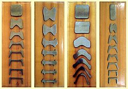
Cross-sections of continuously rolled structural shapes, showing the change induced by each rolling mill
Controlled rolling is a type of thermomechanical processing which integrates controlled deformation and heat treating. The heat which brings the workpiece above the recrystallization temperature is also used to perform the heat treatments so that any subsequent heat treating is unnecessary. Types of heat treatments include the production of a fine grain structure; controlling the nature, size, and distribution of various transformation products (such as ferrite, austenite, pearlite, bainite, and martensite in steel); inducing precipitation hardening; and, controlling the toughness. In order to achieve this the entire process must be closely monitored and controlled. Common variables in controlled rolling include the starting material composition and structure, deformation levels, temperatures at various stages, and cool-down conditions. The benefits of controlled rolling include better mechanical properties and energy savings.[12]
Forge rolling
Forge rolling is a longitudinal rolling process to reduce the cross-sectional area of heated bars or billets by leading them between two contrary rotating roll segments. The process is mainly used to provide optimized material distribution for subsequent die forging processes. Owing to this a better material utilization, lower process forces and better surface quality of parts can be achieved in die forging processes.[22]
Basically any forgeable metal can also be forge-rolled. Forge rolling is mainly used to preform long-scaled billets through targeted mass distribution for parts such as crankshafts, connection rods, steering knuckles and vehicle axles. Narrowest manufacturing tolerances can only partially be achieved by forge rolling. This is the main reason why forge rolling is rarely used for finishing, but mainly for preforming.[23]
A rolling mill, also known as a reduction mill or mill, has a common construction independent of the specific type of rolling being performed:[25]
Rolling millsRolling mill for cold rolling metal sheet like this piece of brass sheet
Work rolls
Backup rolls – are intended to provide rigid support required by the working rolls to prevent bending under the rolling load
Rolling balance system – to ensure that the upper work and back up rolls are maintained in proper position relative to lower rolls
Roll changing devices – use of an overhead crane and a unit designed to attach to the neck of the roll to be removed from or inserted into the mill.
Mill protection devices – to ensure that forces applied to the backup roll chocks are not of such a magnitude to fracture the roll necks or damage the mill housing
Roll cooling and lubrication systems
Pinions – gears to divide power between the two spindles, rotating them at the same speed but in different directions
Gearing – to establish desired rolling speed
Drive motors – rolling narrow foil product to thousands of horsepower
Electrical controls – constant and variable voltages applied to the motors
Coilers and uncoilers – to unroll and roll up coils of metal
Slabs are the feed material for hot strip mills or plate mills and blooms are rolled to billets in a billet mill or large sections in a structural mill. The output from a strip mill is coiled and, subsequently, used as the feed for a cold rolling mill or used directly by fabricators. Billets, for re-rolling, are subsequently rolled in either a merchant, bar or rod mill. Merchant or bar mills produce a variety of shaped products such as angles, channels, beams, rounds (long or coiled) and hexagons.
Configurations
Various rolling configurations. Key: A. 2-high B. 3-high C. 4-high D. 6-high E. 12-high cluster & F. 20-high Sendzimir Mill cluster
Mills are designed in different types of configurations, with the most basic being a two-high non-reversing, which means there are two rolls that only turn in one direction. The two-high reversing mill has rolls that can rotate in both directions, but the disadvantage is that the rolls must be stopped, reversed, and then brought back up to rolling speed between each pass. To resolve this, the three-high mill was invented, which uses three rolls that rotate in one direction; the metal is fed through two of the rolls and then returned through the other pair. The disadvantage to this system is the workpiece must be lifted and lowered using an elevator. All of these mills are usually used for primary rolling and the roll diameters range from 60 to 140cm (24 to 55in).[10]
To minimize the roll diameter a four-high or cluster mill is used. A small roll diameter is advantageous because less roll is in contact with the material, which results in a lower force and power requirement. The problem with a small roll is a reduction of stiffness, which is overcome using backup rolls. These backup rolls are larger and contact the back side of the smaller rolls. A four-high mill has four rolls, two small and two large. A cluster mill has more than four rolls, usually in three tiers. These types of mills are commonly used to hot roll wide plates, most cold rolling applications, and to roll foils.[10]
This sketch shows the components of a four-high Mill Stand
Historically mills were classified by the product produced:[26]
Blooming, cogging and slabbing mills, being the preparatory mills to rolling finished rails, shapes or plates, respectively. If reversing, they are from 34 to 48inches in diameter, and if three-high, from 28 to 42inches in diameter.
Billet mills, three-high, rolls from 24 to 32inches in diameter, used for the further reduction of blooms down to 1.5x1.5-inch billets, being the nubpreparatory mills for the bar and rod
Beam mills, three-high, rolls from 28 to 36inches in diameter, for the production of heavy beams and channels 12inches and over.
Rail mills with rolls from 26 to 40inches in diameter.
Shape mills with rolls from 20 to 26inches in diameter, for smaller sizes of beams and channels and other structural shapes.
Merchant bar mills with rolls from 16 to 20inches in diameter.
Small merchant bar mills with finishing rolls from 8 to 16inches in diameter, generally arranged with a larger size roughing stand.
Rod and wire mills with finishing rolls from 8 to 12inches in diameter, always arranged with larger size roughing stands.
Hoop and cotton tie mills, similar to small merchant bar mills.
Armour plate mills with rolls from 44 to 50inches in diameter and 140 to 180-inch body.
Plate mills with rolls from 28 to 44inches in diameter.
Sheet mills with rolls from 20 to 32inches in diameter.
Universal mills for the production of square-edged or so-called universal plates and various wide flanged shapes by a system of vertical and horizontal rolls.
A tandem mill is a special type of modern rolling mill where rolling is done in one pass. In a traditional rolling mill rolling is done in several passes, but in tandem mill there are several stands (>=2 stands) and reductions take place successively. The number of stands ranges from 2 to 18.
Tandem mills can be either of hot or cold rolling mill types.
Cold rolling mills may be further divided into continuous or batch processing.
A continuous mill has a looping tower which allows the mill to continue rolling slowly the strip in the tower, while a strip welder joins the tail of the current coil to the head of the next coil. At the exit end of the mill there is normally a flying shear (to cut the strip at or near the weld) followed by two coilers; one being unloaded while the other winds on the current coil.
In hot rolling, if the temperature of the workpiece is not uniform the flow of the material will occur more in the warmer parts and less in the cooler. If the temperature difference is great enough cracking and tearing can occur.[10] The cooler sections are, among other things, a result of the supports in the re-heat furnace.
When cold rolling, virtually all of the strip thickness variation is the result of the eccentricity and out-of-roundness of the Back-up Rolls from about Stand 3 of the Hot Strip Mill through to the Finished Product.
Hydraulic piston correcting out-of-round BU Roll
The Back-up Roll eccentricity can be up to 100μm in magnitude per stack. The eccentricity can be measured off-line by plotting the force variation against time with the Mill on creep, no strip present, and the Mill Stand below face.
A modified Fourier analysis was employed by the 5 Stand Cold Mill at Bluescope Steel, Port Kembla from 1986 until that Cold Mill ceased production in 2009. Within each coil, the exit thickness deviation times 10 for every meter of strip was stored in a file. This file was analyzed separately for each frequency/wavelength from 5m to 60m in steps of 0.1m. To improve the accuracy, care was taken to use a full multiple of each wavelength (100*). The calculate amplitudes were plotted against the wavelength, so that the spikes could be compared to the expected wavelengths created by the Backup Rolls of each Stand.
If a Mill Stand is fitted with Hydraulic Pistons in series with, or instead of the electrically driven Mechanical Screws, then it is possible to eliminate the effect of that Stands Back-up Roll eccentricity. While rolling, the eccentricity of each Back-up Roll is determined by sampling the roll force and assigning it to the corresponding portion of each Back-up Roll's rotational position. These recordings are then used to operate the Hydraulic Piston so as to neutralize the eccentricities.
Flatness and shape
In a flat metal workpiece, the flatness is a descriptive attribute characterizing the extent of the geometric deviation from a reference plane. The deviation from complete flatness is the direct result of the workpiece relaxation after hot or cold rolling, due to the internal stress pattern caused by the non-uniform transversal compressive action of the rolls and the uneven geometrical properties of the entry material. The transverse distribution of differential strain/elongation-induced stress with respect to the material's average applied stress is commonly referenced to as shape. Due to the strict relationship between shape and flatness, these terms can be used in an interchangeable manner. In the case of metal strips and sheets, the flatness reflects the differential fiber elongation across the width of the workpiece. This property must be subject to an accurate feedback-based control in order to guarantee the machinability of the metal sheets in the final transformation processes. Some technological details about the feedback control of flatness are given in.[27]
Profile
Profile is made up of the measurements of crown and wedge. Crown is the thickness in the center as compared to the average thickness at the edges of the workpiece. Wedge is a measure of the thickness at one edge as opposed to the other edge. Both may be expressed as absolute measurements or as relative measurements. For instance, one could have 2mil of crown (the center of the workpiece is 2mil thicker than the edges), or one could have 2% crown (the center of the workpiece is 2% thicker than the edges).
It is typically desirable to have some crown in the workpiece as this will cause the workpiece to tend to pull to the center of the mill, and thus will run with higher stability.
Flatness
Roll deflection
Maintaining a uniform gap between the rolls is difficult because the rolls deflect under the load required to deform the workpiece. The deflection causes the workpiece to be thinner on the edges and thicker in the middle. This can be overcome by using a crowned roller (parabolic crown), however the crowned roller will only compensate for one set of conditions, specifically the material, temperature, and amount of deformation.[12]
Other methods of compensating for roll deformation include continual varying crown (CVC), pair cross rolling, and work roll bending. CVC was developed by SMS-Siemag AG and involves grinding a third order polynomial curve into the work rolls and then shifting the work rolls laterally, equally, and opposite to each other. The effect is that the rolls will have a gap between them that is parabolic in shape, and will vary with lateral shift, thus allowing for control of the crown of the rolls dynamically. Pair cross rolling involves using either flat or parabolically crowned rolls, but shifting the ends at an angle so that the gap between the edges of the rolls will increase or decrease, thus allowing for dynamic crown control. Work roll bending involves using hydraulic cylinders at the ends of the rolls to counteract roll deflection.
Another way to overcome deflection issues is by decreasing the load on the rolls, which can be done by applying a longitudinal force; this is essentially drawing. Other method of decreasing roll deflection include increasing the elastic modulus of the roll material and adding back-up supports to the rolls.[12]
The different classifications for flatness defects are:
Symmetrical edge wave - the edges on both sides of the workpiece are "wavy" due to the material at the edges being longer than the material in the center.
Asymmetrical edge wave - one edge is "wavy" due to the material at one side being longer than the other side.
Center buckle - The center of the strip is "wavy" due to the strip in the center being longer than the strip at the edges.
Quarter buckle - This is a rare defect where the fibers are elongated in the quarter regions (the portion of the strip between the center and the edge). This is normally attributed to using excessive roll bending force since the bending force may not compensate for the roll deflection across the entire length of the roll.
One could have a flatness defect even with the workpiece having the same thickness across the width. Also, one could have fairly high crown or wedge, but still produce material that is flat. In order to produce flat material, the material must be reduced by the same percentage across the width. This is important because mass flow of the material must be preserved, and the more a material is reduced, the more it is elongated. If a material is elongated in the same manner across the width, then the flatness coming into the mill will be preserved at the exit of the mill.
Draught
The difference between the thickness of initial and rolled metal piece is called Draught. Thus if is initial thickness and is final thickness, then the draught d is given by
The maximum draught that can be achieved via rollers of radius R with coefficient of static friction f between the roller and the metal surface is given by
This is the case when the frictional force on the metal from inlet contact matches the negative force from the exit contact.
This type of defect occurs when a corner or fin is folded over and rolled but not welded into the metal.[29] They appear as seams across the surface of the metal.
These are long patches of loose metal that have been rolled into the surface of the metal.
Seams
They are open, broken lines that run along the length of the metal and caused by the presence of scale as well as due to pass roughness of Roughing mill.
Slivers
Prominent surface ruptures.
Surface defect remediation
Many surface defects can be scarfed off the surface of semi-finished rolled products before further rolling. Methods of scarfing have included hand-chipping with chisels (18th and 19th centuries); powered chipping and grinding with air chisels and grinders; burning with an oxy-fuel torch, whose gas pressure blows away the metal or slag melted by the flame;[30] and laser scarfing.
↑ Landes, David. S. (1969). The Unbound Prometheus: Technological Change and Industrial Development in Western Europe from 1750 to the Present. Cambridge, New York: Press Syndicate of the University of Cambridge. p.91. ISBN978-0-521-09418-4.
↑ Swank, James M.,History of the Manufacturers of Iron in All Ages, Published by Burt Franklin 1892, p.91
↑ Capece Minutolo, F.; Durante, M.; Lambiase, F.; Langella, A. (2005). "Dimensional Analysis in Steel Rod Rolling for Different Types of Grooves". Journal of Materials Engineering and Performance. 14 (3): 373–377. Bibcode:2005JMEP...14..373C. doi:10.1361/01599490523913. S2CID136821434.
↑ Capece Minutolo, F.; Durante, M.; Lambiase, F.; Langella, A. (2006). "Dimensional analysis of a new type of groove for steel rebar rolling". Journal of Materials Processing Technology. 175 (1–3): 69–76. doi:10.1016/j.jmatprotec.2005.04.042.
↑ Lambiase, F. (2014). "Prediction of geometrical profile in slit rolling pass". The International Journal of Advanced Manufacturing Technology. 71 (5–8): 1285–1293. doi:10.1007/s00170-013-5584-7. S2CID110784133.
↑ Lambiase, F. (2013). "Optimization of shape rolling sequences by integrated artificial intelligent techniques". The International Journal of Advanced Manufacturing Technology. 68 (1–4): 443–452. doi:10.1007/s00170-013-4742-2. S2CID111150929.
↑ Pin, G; Francesconi, V; Cuzzola, FA; Parisini, T (2012). "Adaptive task-space metal strip-flatness control in cold multi-roll mill stands". Journal of Process Control. 23 (2): 108–119. doi:10.1016/j.jprocont.2012.08.008.
This page is based on this Wikipedia article Text is available under the CC BY-SA 4.0 license; additional terms may apply. Images, videos and audio are available under their respective licenses.