Optical fiber designed to carry only a single mode of light, the transverse mode
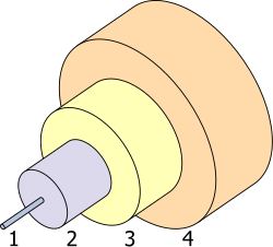
The structure of a typical single-mode fiber:
Core 8–9μm diameter
Cladding 125μm diameter
Buffer 250μm diameter
Jacket 900μm diameter
In fiber-optic communication, a single-mode optical fiber, also known as fundamental- or mono-mode,[1] is an optical fiber designed to carry only a single mode of light - the transverse mode. Modes are the possible solutions of the Helmholtz equation for waves, which is obtained by combining Maxwell's equations and the boundary conditions. These modes define the way the wave travels through space, i.e. how the wave is distributed in space. Waves can have the same mode but have different frequencies. This is the case in single-mode fibers, where we can have waves with different frequencies, but of the same mode, which means that they are distributed in space in the same way, and that gives us a single ray of light. Although the ray travels parallel to the length of the fiber, it is often called transverse mode since its electromagnetic oscillations occur perpendicular (transverse) to the length of the fiber. The 2009 Nobel Prize in Physics was awarded to Charles K. Kao for his theoretical work on the single-mode optical fiber.[2] The standards G.652 and G.657 define the most widely used forms of single-mode optical fiber.[3]
At the Corning Glass Works (now Corning Inc.), Robert Maurer, Donald Keck and Peter Schultz started with fused silica, a material that can be made extremely pure, but has a high melting point and a low refractive index. They made cylindrical preforms by depositing purified materials from the vapor phase, adding carefully controlled levels of dopants to make the refractive index of the core slightly higher than that of the cladding, without raising attenuation dramatically. In September 1970, they announced they had made single-mode fibers with attenuation at the 633-nanometer helium-neon line below 20dB/km.[6]
Characteristics
Unlike multi-mode optical fiber, single-mode fiber does not exhibit modal dispersion. This is due to the fiber having such a small cross section that only the first mode is transported. Single-mode fibers are therefore better at retaining the fidelity of each light pulse over longer distances than multi-mode fibers. For these reasons, single-mode fibers can have a higher bandwidth than multi-mode fibers. Equipment for single-mode fiber is more expensive than equipment for multi-mode optical fiber, but the single-mode fiber itself is usually cheaper in bulk. [citation needed]
Cross section of a single-mode optical fiber patch cord end, taken with a fiberscope. The outermost circle is the cladding, 125μm in diameter. Debris is visible as a streak on the cross-section, and glows due to the illumination.
A typical single-mode optical fiber has a core diameter between 8 and 10.5μm[7] and a cladding diameter of 125μm. There are a number of special types of single-mode optical fiber which have been chemically or physically altered to give special properties, such as dispersion-shifted fiber and nonzero dispersion-shifted fiber. Data rates are limited by polarization mode dispersion and chromatic dispersion. As of 2005[update], data rates of up to 10 gigabits per second were possible at distances of over 80km (50mi) with commercially available transceivers (Xenpak). By using optical amplifiers and dispersion-compensating devices, state-of-the-art DWDM optical systems can span thousands of kilometers at 10 Gbit/s, and several hundred kilometers at 40 Gbit/s.[citation needed]
The lowest-order bounds mode is ascertained for the wavelength of interest by solving Maxwell's equations for the boundary conditions imposed by the fiber, which are determined by the core diameter and the refractive indices of the core and cladding. The solution of Maxwell's equations for the lowest order bound mode will permit a pair of orthogonally polarized fields in the fiber, and this is the usual case in a communication fiber.
In step-index guides, single-mode operation occurs when the normalized frequency, V, is less than or equal to 2.405. For power-law profiles, single-mode operation occurs for a normalized frequency, V, less than approximately
,
where g is the profile parameter.
In practice, the orthogonal polarizations may not be associated with degenerate modes.
OS1 and OS2 are standard 9/125μm single-mode optical fiber. Both are used with wavelengths 1310nm and 1550nm. OS1 has a maximum attenuation of 1dB/km and OS2 is a maximum of 0.4dB/km. OS1 is defined in ISO/IEC 11801,[8] and OS2 is defined in ISO/IEC 24702.[9]
Connectors
Optical fiber connectors are used to join optical fibers where a connect/disconnect capability is required. The basic connector unit is a connector assembly. A connector assembly consists of an adapter and two connector plugs. Due to the sophisticated polishing and tuning procedures that may be incorporated into optical connector manufacturing, connectors are generally assembled onto optical fiber in a supplier's manufacturing facility. However, the assembly and polishing operations involved can be performed in the field, for example to make cross-connect jumpers to size.
Optical fiber connectors are used in telephone company central offices, at installations on customer premises, and in outside plant applications. Their uses include:
Making the connection between equipment and the telephone plant in the central office
Connecting fibers to remote and outside plant electronics such as optical network units (ONUs) and digital loop carrier (DLC) systems
Optical cross connects in the central office
Patching panels in the outside plant to provide architectural flexibility and to interconnect fibers belonging to different service providers
Connecting couplers, splitters, and wavelength-division multiplexers (WDMs) to optical fibers
Connecting optical test equipment to fibers for testing and maintenance.
Outside plant applications may involve locating connectors underground in subsurface enclosures that may be subject to flooding, on outdoor walls, or on utility poles. The closures that enclose them may be hermetic, or may be "free-breathing". Hermetic closures will prevent the connectors within being subjected to temperature swings unless they are breached. Free-breathing enclosures will subject them to temperature and humidity swings, and possibly to condensation and biological action from airborne bacteria, insects, etc. Connectors in the underground plant may be subjected to groundwater immersion if the closures containing them are breached or improperly assembled.
The latest industry requirements for optical fiber connectors are in TelcordiaGR-326, Generic Requirements for Single-Mode Optical Connectors and Jumper Assemblies.
A multi-fiber optical connector is designed to simultaneously join multiple optical fibers together, with each optical fiber being joined to only one other optical fiber.
The last part of the definition is included so as not to confuse multi-fiber connectors with a branching component, such as a coupler. The latter joins one optical fiber to two or more other optical fibers.
Multi-fiber optical connectors are designed to be used wherever quick and/or repetitive connects and disconnects of a group of fibers are needed. Applications include telecommunications companies' central offices (COs), installations on customer premises, and outside plant (OSP) applications.
The multi-fiber optical connector can be used in the creation of a low-cost switch for use in fiber optical testing. Another application is in cables delivered to a user with pre-terminated multi-fiber jumpers. This would reduce the need for field splicing, which could greatly reduce the number of hours necessary for placing an optical fiber cable in a telecommunications network. This, in turn, would result in savings for the installer of such cable.
Industry requirements for multi-fiber optical connectors are covered in GR-1435, Generic Requirements for Multi-Fiber Optical Connectors.
Fiber optic switches
An optical switch is a component with two or more ports that selectively transmits, redirects, or blocks an optical signal in a transmission medium.[10] According to TelcordiaGR-1073, an optical switch must be actuated to select or change between states. The actuating signal (also referred to as the control signal) is usually electrical, but in principle, could be optical or mechanical. (The control signal format may be Boolean and may be an independent signal; or, in the case of optical actuation, the control signal may be encoded in the input data signal. Switch performance is generally intended to be independent of wavelength within the component passband.)
Quadruply clad fiber
In fiber optics, a quadruply clad fiber is a single-mode optical fiber that has four claddings.[11] Each cladding has a refractive index lower than that of the core. With respect to one another, their relative refractive indices are, in order of distance from the core: lowest, highest, lower, higher.
A quadruply clad fiber has the advantage of very low macrobending losses. It also has two zero-dispersion points, and moderately low dispersion over a wider wavelength range than a singly clad fiber or a doubly clad fiber.
↑Tricker, R. (2003). "Optical Fibres in Power Systems". Electrical Engineer's Reference Book. doi:10.1016/B978-075064637-6/50037-X. ISBN978-0-7506-4637-6. p.37/4: Single-mode fibre (also referred to as fundamental or mono-mode fibre)...
This page is based on this Wikipedia article Text is available under the CC BY-SA 4.0 license; additional terms may apply. Images, videos and audio are available under their respective licenses.