A tire or tyre is a ring-shaped component that surrounds a wheel's rim to transfer a vehicle's load from the axle through the wheel to the ground and to provide traction on the surface over which the wheel travels. Most tires, such as those for automobiles and bicycles, are pneumatically inflated structures, which also provide a flexible cushion that absorbs shock as the tire rolls over rough features on the surface. Tires provide a footprint, called a contact patch, that is designed to match the weight of the vehicle with the bearing strength of the surface that it rolls over by providing a bearing pressure that will not deform the surface excessively.

Suspension is the system of tires, tire air, springs, shock absorbers and linkages that connects a vehicle to its wheels and allows relative motion between the two. Suspension systems must support both road holding/handling and ride quality, which are at odds with each other. The tuning of suspensions involves finding the right compromise. It is important for the suspension to keep the road wheel in contact with the road surface as much as possible, because all the road or ground forces acting on the vehicle do so through the contact patches of the tires. The suspension also protects the vehicle itself and any cargo or luggage from damage and wear. The design of front and rear suspension of a car may be different.
Automobile handling and vehicle handling are descriptions of the way a wheeled vehicle responds and reacts to the inputs of a driver, as well as how it moves along a track or road. It is commonly judged by how a vehicle performs particularly during cornering, acceleration, and braking as well as on the vehicle's directional stability when moving in steady state condition.

The caster angle or castor angle is the angular displacement of the steering axis from the vertical axis of a steered wheel in a car, motorcycle, bicycle, other vehicle or a vessel, as seen from the side of the vehicle. The steering axis in a car with dual ball joint suspension is an imaginary line that runs through the center of the upper ball joint to the center of the lower ball joint, or through the center of the kingpin for vehicles having a kingpin.

Rolling is a type of motion that combines rotation and translation of that object with respect to a surface, such that, if ideal conditions exist, the two are in contact with each other without sliding.

Rolling resistance, sometimes called rolling friction or rolling drag, is the force resisting the motion when a body rolls on a surface. It is mainly caused by non-elastic effects; that is, not all the energy needed for deformation of the wheel, roadbed, etc., is recovered when the pressure is removed. Two forms of this are hysteresis losses, and permanent (plastic) deformation of the object or the surface. Note that the slippage between the wheel and the surface also results in energy dissipation. Although some researchers have included this term in rolling resistance, some suggest that this dissipation term should be treated separately from rolling resistance because it is due to the applied torque to the wheel and the resultant slip between the wheel and ground, which is called slip loss or slip resistance. In addition, only the so-called slip resistance involves friction, therefore the name "rolling friction" is to an extent a misnomer.
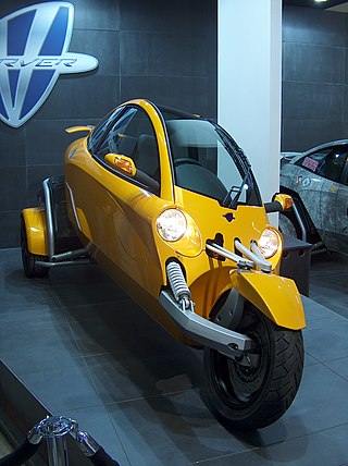
A tilting three-wheeler, tilting trike, leaning trike, or even just tilter, is a three-wheeled vehicle and usually a narrow-track vehicle whose body and or wheels tilt in the direction of a turn. Such vehicles can corner without rolling over despite having a narrow axle track because they can balance some or all of the roll moment caused by centripetal acceleration with an opposite roll moment caused by gravity, as bicycles and motorcycles do. This also reduces the lateral acceleration experienced by the rider, which some find more comfortable than the alternative. The narrow profile can result in reduced aerodynamic drag and increased fuel efficiency. These types of vehicles have also been described as "man-wide vehicles" (MWV).

An adhesion railway relies on adhesion traction to move the train. Adhesion traction is the friction between the drive wheels and the steel rail. The term "adhesion railway" is used only when it is necessary to distinguish adhesion railways from railways moved by other means, such as by a stationary engine pulling on a cable attached to the cars or by railways that are moved by a pinion meshing with a rack.

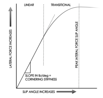
Cornering force or side force is the lateral force produced by a vehicle tire during cornering.

A beam axle, rigid axle or solid axle is a dependent suspension design in which a set of wheels is connected laterally by a single beam or shaft. Beam axles were once commonly used at the rear wheels of a vehicle, but historically they have also been used as front axles in four-wheel-drive vehicles. In most automobiles, beam axles have been replaced with front and rear independent suspensions.

Bicycle and motorcycle dynamics is the science of the motion of bicycles and motorcycles and their components, due to the forces acting on them. Dynamics falls under a branch of physics known as classical mechanics. Bike motions of interest include balancing, steering, braking, accelerating, suspension activation, and vibration. The study of these motions began in the late 19th century and continues today.
Directional stability is stability of a moving body or vehicle about an axis which is perpendicular to its direction of motion. Stability of a vehicle concerns itself with the tendency of a vehicle to return to its original direction in relation to the oncoming medium when disturbed (rotated) away from that original direction. If a vehicle is directionally stable, a restoring moment is produced which is in a direction opposite to the rotational disturbance. This "pushes" the vehicle so as to return it to the original orientation, thus tending to keep the vehicle oriented in the original direction.
A Bundorf analysis is a measure of the characteristics of a vehicle that govern its understeer balance. The understeer is measured in units of degrees of additional yaw per g of lateral acceleration.
Hans Bastiaan Pacejka was an expert in vehicle system dynamics and particularly in tire dynamics, fields in which his works are now standard references. He was Professor emeritus at Delft University of Technology in Delft, Netherlands.
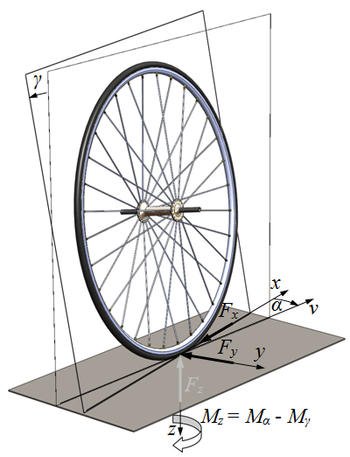
In (automotive) vehicle dynamics, slip is the relative motion between a tire and the road surface it is moving on. This slip can be generated either by the tire's rotational speed being greater or less than the free-rolling speed, or by the tire's plane of rotation being at an angle to its direction of motion.

Self aligning torque (SAT), also known as aligning torque or aligning moment, is the torque that a tire creates as it rolls along, which tends to steer it, i.e. rotate it around its vertical axis. In the presence of a non-zero slip angle, this torque tends to steer the tire toward the direction in which it is traveling, hence its name.

Pneumatic trail or trail of the tire is a trail-like effect generated by compliant tires rolling on a hard surface and subject to side loads, as in a turn. More technically, it is the distance that the resultant force of side-slip occurs behind the geometric center of the contact patch.

Camber thrust and camber force are terms used to describe the force generated perpendicular to the direction of travel of a rolling tire due to its camber angle and finite contact patch. Camber thrust is generated when a point on the outer surface of a leaned and rotating tire, that would normally follow a path that is elliptical when projected onto the ground, is forced to follow a straight path while coming in contact with the ground, due to friction. This deviation towards the direction of the lean causes a deformation in the tire tread and carcass that is transmitted to the vehicle as a force in the direction of the lean.

Relaxation length is a property of pneumatic tires that describes the delay between when a slip angle is introduced and when the cornering force reaches its steady-state value. It is also described as the distance that a tire rolls before the lateral force builds up to 63% of its steady-state value. It can be calculated as the ratio of cornering stiffness over the lateral stiffness, where cornering stiffness is the ratio of cornering force over slip angle, and lateral stiffness is the ratio of lateral force over lateral displacement.

The following outline is provided as an overview of and topical guide to tires: