
Very high frequency (VHF) is the ITU designation for the range of radio frequency electromagnetic waves from 30 to 300 megahertz (MHz), with corresponding wavelengths of ten meters to one meter. Frequencies immediately below VHF are denoted high frequency (HF), and the next higher frequencies are known as ultra high frequency (UHF).

Radio navigation or radionavigation is the application of radio frequencies to determine a position of an object on the Earth, either the vessel or an obstruction. Like radiolocation, it is a type of radiodetermination.

In aviation, the instrument landing system (ILS) is a precision radio navigation system that provides short-range guidance to aircraft to allow them to approach a runway at night or in bad weather. In its original form, it allows an aircraft to approach until it is 200 feet (61 m) over the ground, within a 1⁄2 mile (800 m) of the runway. At that point the runway should be visible to the pilot; if it is not, they perform a missed approach. Bringing the aircraft this close to the runway dramatically increases the range of weather conditions in which a safe landing can be made. Other versions of the system, or "categories", have further reduced the minimum altitudes, runway visual ranges (RVRs), and transmitter and monitoring configurations designed depending on the normal expected weather patterns and airport safety requirements.

A non-directional beacon (NDB) or non-directional radio beacon is a radio beacon which does not include inherent directional information. Radio beacons are radio transmitters at a known location, used as an aviation or marine navigational aid. NDB are in contrast to directional radio beacons and other navigational aids, such as low-frequency radio range, VHF omnidirectional range (VOR) and tactical air navigation system (TACAN).

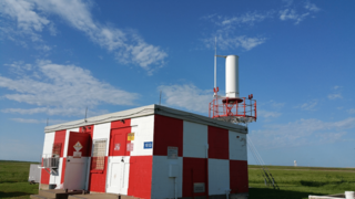
Very high frequency omni-directional station (VOR) is a type of short-range radio navigation system for aircraft, enabling aircraft with a receiving unit to determine its position and stay on course by receiving radio signals transmitted by a network of fixed ground radio beacons. It uses frequencies in the very high frequency (VHF) band from 108.00 to 117.95 MHz. Developed in the United States beginning in 1937 and deployed by 1946, VOR became the standard air navigational system in the world, used by both commercial and general aviation, until supplanted by satellite navigation systems such as GPS in the early 21st century. As such, VOR stations are being gradually decommissioned. In 2000 there were about 3,000 VOR stations operating around the world, including 1,033 in the US, but by 2013 the number in the US had been reduced to 967. The United States is decommissioning approximately half of its VOR stations and other legacy navigation aids as part of a move to performance-based navigation, while still retaining a "Minimum Operational Network" of VOR stations as a backup to GPS. In 2015, the UK planned to reduce the number of stations from 44 to 19 by 2020.
In aviation, distance measuring equipment (DME) is a radio navigation technology that measures the slant range (distance) between an aircraft and a ground station by timing the propagation delay of radio signals in the frequency band between 960 and 1215 megahertz (MHz). Line-of-visibility between the aircraft and ground station is required. An interrogator (airborne) initiates an exchange by transmitting a pulse pair, on an assigned 'channel', to the transponder ground station. The channel assignment specifies the carrier frequency and the spacing between the pulses. After a known delay, the transponder replies by transmitting a pulse pair on a frequency that is offset from the interrogation frequency by 63 MHz and having specified separation.

In the United States, airways or air routes are defined by the Federal Aviation Administration (FAA) in two ways:
A tactical air navigation system, commonly referred to by the acronym TACAN, is a navigation system used by military aircraft. It provides the user with bearing and distance to a ground or ship-borne station. It is a more accurate version of the VOR/DME system that provides bearing and range information for civil aviation. The DME portion of the TACAN system is available for civil use; at VORTAC facilities where a VOR is combined with a TACAN, civil aircraft can receive VOR/DME readings. Aircraft equipped with TACAN avionics can use this system for en route navigation as well as non-precision approaches to landing fields. The Space Shuttle is one such vehicle that was designed to use TACAN navigation but later upgraded with GPS as a replacement.
Airband or aircraft band is the name for a group of frequencies in the VHF radio spectrum allocated to radio communication in civil aviation, sometimes also referred to as VHF, or phonetically as "Victor". Different sections of the band are used for radionavigational aids and air traffic control.
The microwave landing system (MLS) is an all-weather, precision radio guidance system intended to be installed at large airports to assist aircraft in landing, including 'blind landings'. MLS enables an approaching aircraft to determine when it is aligned with the destination runway and on the correct glidepath for a safe landing. MLS was intended to replace or supplement the instrument landing systems (ILS). MLS has a number of operational advantages over ILS, including a wider selection of channels to avoid interference with nearby installations, excellent performance in all weather, a small "footprint" at the airports, and wide vertical and horizontal "capture" angles that allowed approaches from wider areas around the airport.
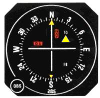
A course deviation indicator (CDI) is an avionics instrument used in aircraft navigation to determine an aircraft's lateral position in relation to a course to or from a radio navigation beacon. If the location of the aircraft is to the left of this course, the needle deflects to the right, and vice versa.

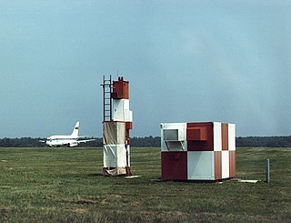
A marker beacon is a particular type of VHF radio beacon used in aviation, usually in conjunction with an instrument landing system (ILS), to give pilots a means to determine position along an established route to a destination such as a runway.
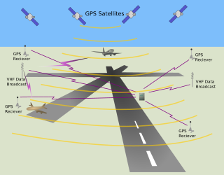
The local-area augmentation system (LAAS) is an all-weather aircraft landing system based on real-time differential correction of the GPS signal. Local reference receivers located around the airport send data to a central location at the airport. This data is used to formulate a correction message, which is then transmitted to users via a VHF Data Link. A receiver on an aircraft uses this information to correct GPS signals, which then provides a standard ILS-style display to use while flying a precision approach. The FAA has stopped using the term LAAS and has transitioned to the International Civil Aviation Organization (ICAO) terminology of Ground-Based Augmentation System (GBAS). While the FAA has indefinitely delayed plans for federal GBAS acquisition, the system can be purchased by airports and installed as a Non-Federal navigation aid.

A transponder landing system (TLS) is an all-weather, precision landing system that uses existing airborne transponder and instrument landing system (ILS) equipment to create a precision approach at a location where an ILS would normally not be available.

The Airports Authority of India, or AAI, is a public sector enterprise under the ownership of the Ministry of Civil Aviation, Government of India. It is responsible for creating, upgrading, maintaining, and managing civil aviation infrastructure in India. It provides Communication Navigation Surveillance/Air Traffic Management (CNS/ATM) services over the Indian airspace and adjoining oceanic areas. AAI currently manages a total of 137 airports, including 34 international airports, 10 Customs Airports, 81 domestic airports, and 23 Civil enclaves at Defence airfields. AAI also has ground installations at all airports and 25 other locations to ensure the safety of aircraft operations. AAI covers all major air routes over the Indian landmass via 29 Radar installations at 11 locations along with 700 VOR/DVOR installations co-located with Distance Measuring Equipment (DME). 52 runways are provided with Instrument landing system (ILS) installations with Night Landing Facilities at most of these airports and an Automatic Message Switching System at 15 Airports.

An airway beacon (US) or aerial lighthouse was a rotating light assembly mounted atop a tower. These were once used extensively in the United States for visual navigation by airplane pilots along a specified airway corridor. In Europe, they were used to guide aircraft with lighted beacons at night.

In navigation, a radio beacon or radiobeacon is a kind of beacon, a device that marks a fixed location and allows direction-finding equipment to find relative bearing. But instead of employing visible light, radio beacons transmit electromagnetic radiation in the radio wave band. They are used for direction-finding systems on ships, aircraft and vehicles.

In radio navigation, a VOR/DME is a radio beacon that combines a VHF omnidirectional range (VOR) with a distance-measuring equipment (DME). The VOR allows the receiver to measure its bearing to or from the beacon, while the DME provides the slant distance between the receiver and the station. Together, the two measurements allow the receiver to compute a position fix.

The Adcock antenna is an antenna array consisting of four equidistant vertical elements which can be used to transmit or receive directional radio waves.

The low-frequency radio range, also known as the four-course radio range, LF/MF four-course radio range, A-N radio range, Adcock radio range, or commonly "the range", was the main navigation system used by aircraft for instrument flying in the 1930s and 1940s, until the advent of the VHF omnidirectional range (VOR), beginning in the late 1940s. It was used for en route navigation as well as instrument approaches and holds.
