
Optics is the branch of physics that studies the behaviour and properties of light, including its interactions with matter and the construction of instruments that use or detect it. Optics usually describes the behaviour of visible, ultraviolet, and infrared light. Light is a type of electromagnetic radiation, and other forms of electromagnetic radiation such as X-rays, microwaves, and radio waves exhibit similar properties.

In optics, the numerical aperture (NA) of an optical system is a dimensionless number that characterizes the range of angles over which the system can accept or emit light. By incorporating index of refraction in its definition, NA has the property that it is constant for a beam as it goes from one material to another, provided there is no refractive power at the interface. The exact definition of the term varies slightly between different areas of optics. Numerical aperture is commonly used in microscopy to describe the acceptance cone of an objective, and in fiber optics, in which it describes the range of angles within which light that is incident on the fiber will be transmitted along it.
The focal length of an optical system is a measure of how strongly the system converges or diverges light; it is the inverse of the system's optical power. A positive focal length indicates that a system converges light, while a negative focal length indicates that the system diverges light. A system with a shorter focal length bends the rays more sharply, bringing them to a focus in a shorter distance or diverging them more quickly. For the special case of a thin lens in air, a positive focal length is the distance over which initially collimated (parallel) rays are brought to a focus, or alternatively a negative focal length indicates how far in front of the lens a point source must be located to form a collimated beam. For more general optical systems, the focal length has no intuitive meaning; it is simply the inverse of the system's optical power.
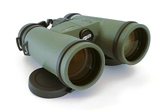
Binoculars or field glasses are two refracting telescopes mounted side-by-side and aligned to point in the same direction, allowing the viewer to use both eyes when viewing distant objects. Most binoculars are sized to be held using both hands, although sizes vary widely from opera glasses to large pedestal-mounted military models.

An optical prism is a transparent optical element with flat, polished surfaces that are designed to refract light. At least one surface must be angled — elements with two parallel surfaces are not prisms. The most familiar type of optical prism is the triangular prism, which has a triangular base and rectangular sides. Not all optical prisms are geometric prisms, and not all geometric prisms would count as an optical prism. Prisms can be made from any material that is transparent to the wavelengths for which they are designed. Typical materials include glass, acrylic and fluorite.
Optics is the branch of physics which involves the behavior and properties of light, including its interactions with matter and the construction of instruments that use or detect it. Optics usually describes the behavior of visible, ultraviolet, and infrared light. Because light is an electromagnetic wave, other forms of electromagnetic radiation such as X-rays, microwaves, and radio waves exhibit similar properties.

In optics, a Porro prism, named for its inventor Ignazio Porro, is a type of reflection prism used in optical instruments to alter the orientation of an image.
A prism coupler is a prism designed to couple a substantial fraction of the power contained in a beam of light into a thin film to be used as a waveguide without the need for precision polishing of the edge of the film, without the need for sub-micrometer alignment precision of the beam and the edge of the film, and without the need for matching the numerical aperture of the beam to the film. Using a prism coupler, a beam coupled into a thin film can have a diameter hundreds of times the thickness of the film. Invention of the coupler contributed to the initiation of a field of study known as integrated optics.
An optical waveguide is a physical structure that guides electromagnetic waves in the optical spectrum. Common types of optical waveguides include optical fiber waveguides, transparent dielectric waveguides made of plastic and glass, liquid light guides, and liquid waveguides.

An autocollimator is an optical instrument for non-contact measurement of angles. They are typically used to align components and measure deflections in optical or mechanical systems. An autocollimator works by projecting an image onto a target mirror and measuring the deflection of the returned image against a scale, either visually or by means of an electronic detector. A visual autocollimator can measure angles as small as 1 arcsecond, while an electronic autocollimator can have up to 100 times more resolution.

A prism compressor is an optical device used to shorten the duration of a positively chirped ultrashort laser pulse by giving different wavelength components a different time delay. It typically consists of two prisms and a mirror. Figure 1 shows the construction of such a compressor. Although the dispersion of the prism material causes different wavelength components to travel along different paths, the compressor is built such that all wavelength components leave the compressor at different times, but in the same direction. If the different wavelength components of a laser pulse were already separated in time, the prism compressor can make them overlap with each other, thus causing a shorter pulse.

In optics, a dispersive prism is an optical prism that is used to disperse light, that is, to separate light into its spectral components. Different wavelengths (colors) of light will be deflected by the prism at different angles. This is a result of the prism material's index of refraction varying with wavelength (dispersion). Generally, longer wavelengths (red) undergo a smaller deviation than shorter wavelengths (blue). The dispersion of white light into colors by a prism led Sir Isaac Newton to conclude that white light consisted of a mixture of different colors.

A coincidence rangefinder or coincidence telemeter is a type of rangefinder that uses the principle of triangulation and an optical device to allow an operator to determine the distance to a visible object. There are subtypes split-image telemeter, inverted image, or double-image telemeter with different principles how two images in a single ocular are compared. Coincidence rangefinders were important elements of fire control systems for long-range naval guns and land-based coastal artillery circa 1890–1960. They were also used in rangefinder cameras.
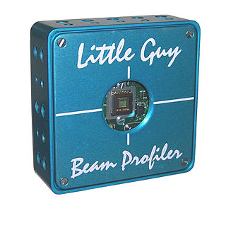
A laser beam profiler captures, displays, and records the spatial intensity profile of a laser beam at a particular plane transverse to the beam propagation path. Since there are many types of lasers—ultraviolet, visible, infrared, continuous wave, pulsed, high-power, low-power—there is an assortment of instrumentation for measuring laser beam profiles. No single laser beam profiler can handle every power level, pulse duration, repetition rate, wavelength, and beam size.

An angle gauge is a tool used by foresters to determine which trees to measure when using a variable radius plot design in forest inventory. Using this tool a forester can quickly measure the trees that are in or out of the plot. An angle gauge is similar to a wedge prism though it must be held a fixed distance from the eye to work properly. Unlike the wedge prism, which is held over the plot center, the surveyor's eye is kept over plot-center when using an angle gauge.
A depolarizer or depolariser is an optical device used to scramble the polarization of light. An ideal depolarizer would output randomly polarized light whatever its input, but all practical depolarizers produce pseudo-random output polarization.

The first description of multiple-prism arrays, and multiple-prism dispersion, was given by Newton in his book Opticks. Prism pair expanders were introduced by Brewster in 1813. A modern mathematical description of the single-prism dispersion was given by Born and Wolf in 1959. The generalized multiple-prism dispersion theory was introduced by Duarte and Piper in 1982.
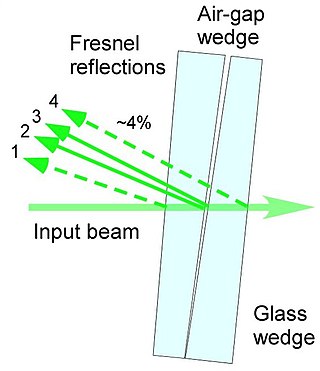
The air-wedge shearing interferometer is probably the simplest type of interferometer designed to visualize the disturbance of the wavefront after propagation through a test object. This interferometer is based on utilizing a thin wedged air-gap between two optical glass surfaces and can be used with virtually any light source even with non-coherent white light.
The operation of a photon scanning tunneling microscope (PSTM) is analogous to the operation of an electron scanning tunneling microscope, with the primary distinction being that PSTM involves tunneling of photons instead of electrons from the sample surface to the probe tip. A beam of light is focused on a prism at an angle greater than the critical angle of the refractive medium in order to induce total internal reflection within the prism. Although the beam of light is not propagated through the surface of the refractive prism under total internal reflection, an evanescent field of light is still present at the surface.

A Perger prism or Perger–Porro prism system is a prism, that is used to invert an image. The special feature of this prism is that, like a traditional double Porro prism system, it manages this with only four beam deflections and has neither a roof edge with the accompanying phase correction problems, a mirrored surface or an air gap. However, in contrast to the traditional double Porro prism, it leads to a significantly reduced eyepiece/objective axis offset. The reduced beam offset allows for slimmer, more straight binocular housings usually found in roof prism binoculars. Complicating production requirements make high-quality roof prism binoculars relatively costly to produce compared to in optical quality equivalent Porro prism or "Perger–Porro prism system" binoculars.


