Very large-scale integration (VLSI) is the process of creating an integrated circuit (IC) by combining millions or billions of MOS transistors onto a single chip. VLSI began in the 1970s when MOS integrated circuit chips were developed and then widely adopted, enabling complex semiconductor and telecommunication technologies. The microprocessor and memory chips are VLSI devices.
In computer engineering, a hardware description language (HDL) is a specialized computer language used to describe the structure and behavior of electronic circuits, and most commonly, digital logic circuits.

An application-specific integrated circuit is an integrated circuit (IC) chip customized for a particular use, rather than intended for general-purpose use, such as a chip designed to run in a digital voice recorder or a high-efficiency video codec. Application-specific standard product chips are intermediate between ASICs and industry standard integrated circuits like the 7400 series or the 4000 series. ASIC chips are typically fabricated using metal–oxide–semiconductor (MOS) technology, as MOS integrated circuit chips.
Siemens EDA is a US-based electronic design automation (EDA) multinational corporation for electrical engineering and electronics, headquartered in Wilsonville, Oregon. Founded in 1981 as Mentor Graphics, the company was acquired by Siemens in 2017.
Electronic design automation (EDA), also referred to as electronic computer-aided design (ECAD), is a category of software tools for designing electronic systems such as integrated circuits and printed circuit boards. The tools work together in a design flow that chip designers use to design and analyze entire semiconductor chips. Since a modern semiconductor chip can have billions of components, EDA tools are essential for their design; this article in particular describes EDA specifically with respect to integrated circuits (ICs).

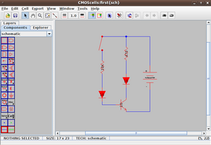
Magic is an electronic design automation (EDA) layout tool for very-large-scale integration (VLSI) integrated circuit (IC) originally written by John Ousterhout and his graduate students at UC Berkeley. Work began on the project in February 1983. A primitive version was operational by April 1983, when Joan Pendleton, Shing Kong and other graduate student chip designers suffered through many fast revisions devised to meet their needs in designing the SOAR CPU chip, a follow-on to Berkeley RISC.

Synopsys is an American electronic design automation (EDA) company that focuses on silicon design and verification, silicon intellectual property and software security and quality. Products include tools for logic synthesis and physical design of integrated circuits, simulators for development and debugging environments that assist in the design of the logic for chips and computer systems. In recent years, Synopsys has expanded its products and services to include application security testing.

Integrated circuit layout, also known IC layout, IC mask layout, or mask design, is the representation of an integrated circuit in terms of planar geometric shapes which correspond to the patterns of metal, oxide, or semiconductor layers that make up the components of the integrated circuit. Originally the overall process was called tapeout as historically early ICs used graphical black crepe tape on mylar media for photo imaging.

GDSII stream format (GDSII), is a binary database file format which is the de facto industry standard for Electronic Design Automation data exchange of integrated circuit or IC layout artwork. It is a binary file format representing planar geometric shapes, text labels, and other information about the layout in hierarchical form. The data can be used to reconstruct all or part of the artwork to be used in sharing layouts, transferring artwork between different tools, or creating photomasks.
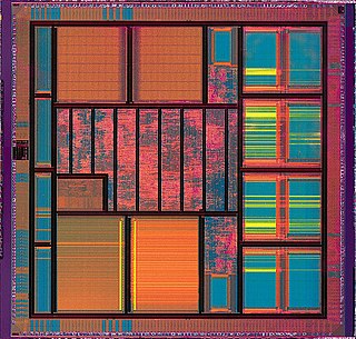
VLSI Technology, Inc., was an American company that designed and manufactured custom and semi-custom integrated circuits (ICs). The company was based in Silicon Valley, with headquarters at 1109 McKay Drive in San Jose. Along with LSI Logic, VLSI Technology defined the leading edge of the application-specific integrated circuit (ASIC) business, which accelerated the push of powerful embedded systems into affordable products.
In semiconductor design, standard-cell methodology is a method of designing application-specific integrated circuits (ASICs) with mostly digital-logic features. Standard-cell methodology is an example of design abstraction, whereby a low-level very-large-scale integration (VLSI) layout is encapsulated into an abstract logic representation.

OrCAD Systems Corporation was a software company that made OrCAD, a proprietary software tool suite used primarily for electronic design automation (EDA). The software is used mainly by electronic design engineers and electronic technicians to create electronic schematics, and perform mixed-signal simulation and electronic prints for manufacturing printed circuit boards (PCBs). OrCAD was taken over by Cadence Design Systems in 1999 and was integrated with Cadence Allegro in 2005.
Integrated circuit design, or IC design, is a sub-field of electronics engineering, encompassing the particular logic and circuit design techniques required to design integrated circuits, or ICs. ICs consist of miniaturized electronic components built into an electrical network on a monolithic semiconductor substrate by photolithography.
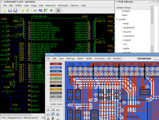
The term gEDA refers to two things:
- A set of software applications used for electronic design released under the GPL. As such, gEDA is an ECAD or EDA application suite. gEDA is mostly oriented towards printed circuit board design. The gEDA applications are often referred to collectively as "the gEDA Suite".
- The collaboration of free software/open-source developers who work to develop and maintain the gEDA toolkit. The developers communicate via gEDA mailing lists, and have participated in the annual "Google Summer of Code" event as a single project. This collaboration is often referred to as "the gEDA Project".
The Layout Versus Schematic (LVS) is the class of electronic design automation (EDA) verification software that determines whether a particular integrated circuit layout corresponds to the original schematic or circuit diagram of the design.

Technology computer-aided design is a branch of electronic design automation that models semiconductor fabrication and semiconductor device operation. The modeling of the fabrication is termed Process TCAD, while the modeling of the device operation is termed Device TCAD. Included are the modelling of process steps, and modelling of the behavior of the electrical devices based on fundamental physics, such as the doping profiles of the devices. TCAD may also include the creation of compact models, which try to capture the electrical behavior of such devices but do not generally derive them from the underlying physics. SPICE simulator itself is usually considered as part of ECAD rather than TCAD.

Electronic circuit simulation uses mathematical models to replicate the behavior of an actual electronic device or circuit. Simulation software allows for modeling of circuit operation and is an invaluable analysis tool. Due to its highly accurate modeling capability, many colleges and universities use this type of software for the teaching of electronics technician and electronics engineering programs. Electronics simulation software engages its users by integrating them into the learning experience. These kinds of interactions actively engage learners to analyze, synthesize, organize, and evaluate content and result in learners constructing their own knowledge.
This page is a comparison of electronic design automation (EDA) software which is used today to design the near totality of electronic devices. Modern electronic devices are too complex to be designed without the help of a computer. Electronic devices may consist of integrated circuits (ICs), printed circuit boards (PCBs), field programmable gate arrays (FPGAs) or a combination of them. Integrated circuits may consist of a combination of digital and analog circuits. These circuits can contain a combination of transistors, resistors, capacitors or specialized components such as analog neural networks, antennas or fuses.
CircuitMaker is electronic design automation software for printed circuit board designs targeted at the hobby, hacker, and maker community. CircuitMaker is available as freeware, and the hardware designed with it may be used for commercial and non-commercial purposes without limitations. It is currently available publicly as version 2.0 by Altium Limited, with the first non-beta release on January 17, 2016.
EasyEDA is a web-based EDA tool suite that enables hardware engineers to design, simulate, share - publicly and privately - and discuss schematics, simulations and printed circuit boards. Other features include the creation of a bill of materials, Gerber files and pick and place files and documentary outputs in PDF, PNG and SVG formats.