Electrical ballast

Last updated
An American electronic instant start ballast for powering a variety of American T8 fluorescent lamps. Fulham Workhorse 4 ballast.jpg
An American electronic instant start ballast for powering a variety of American T8 fluorescent lamps.
Variety of ballasts for fluorescent and other discharge lamps LAjaHID.jpg
Variety of ballasts for fluorescent and other discharge lamps

An electrical ballast is a device placed in series with a load to limit the amount of current in an electrical circuit.

Contents

A familiar and widely used example is the inductive ballast used in fluorescent lamps to limit the current through the tube, which would otherwise rise to a destructive level due to the negative differential resistance of the tube's voltage-current characteristic.

Ballasts vary greatly in complexity. They may be as simple as a resistor, inductor, or capacitor (or a combination of these) wired in series with the lamp; or as complex as the electronic ballasts used in compact fluorescent lamps (CFLs).

Current limiting

A typical 230V, 50hz series choke ballast (inductor) used in older lighting. This example is used for a tanning lamp. It requires a starter switch (below). Tanning-chokeballast.jpg
A typical 230V, 50hz series choke ballast (inductor) used in older lighting. This example is used for a tanning lamp. It requires a starter switch (below).
A lamp starter, required with some inductor type ballasts. It connects the two ends of the lamp to preheat them for one second before lighting. Tanning-starter.jpg
A lamp starter, required with some inductor type ballasts. It connects the two ends of the lamp to preheat them for one second before lighting.

An electrical ballast is a device that limits the current through an electrical load. These are most often used when a load (such as an arc discharge) has its terminal voltage decline when current through the load increases. If such a device were connected to a constant-voltage power supply, it would draw an increasing amount of current until it is destroyed or causes the power supply to fail. To prevent this, a ballast provides a positive resistance or reactance that limits the current. The ballast provides for the proper operation of the negative-resistance device by limiting current.

Ballasts can also be used simply to limit the current in an ordinary, positive-resistance circuit. Prior to the advent of solid-state ignition, automobile ignition systems commonly included a ballast resistor to regulate the voltage applied to the ignition system.

Resistors

Fixed resistors

For simple, low-powered loads such as a neon lamp, a fixed resistor is commonly used. Because the resistance of the ballast resistor is large it determines the current in the circuit, even in the face of negative resistance introduced by the neon lamp.

Ballast was also a component used in early model automobile engines that lowered the supply voltage to the ignition system after the engine had been started. Starting the engine requires a significant amount of electrical current from the battery, resulting in an equally significant voltage drop. To allow the engine to start, the ignition system was designed to operate on this lower voltage. But once the vehicle was started and the starter disengaged, the normal operating voltage was too high for the ignition system. To avoid this problem, a ballast resistor was inserted in series with the ignition system, resulting in two different operating voltages for the starting and ignition systems.

Occasionally, this ballast resistor would fail and the classic symptom of this failure was that the engine ran while being cranked (while the resistor was bypassed) but stalled immediately when cranking ceased (and the resistor was reconnected in the circuit via the ignition switch). Modern electronic ignition systems (those used since the 1980s or late '70s) do not require a ballast resistor as they are flexible enough to operate on the lower cranking voltage or the normal operating voltage.

Another common use of a ballast resistor in the automotive industry is adjusting the ventilation fan speed. The ballast is a fixed resistor with usually two center taps, and the fan speed selector switch is used to bypass portions of the ballast: all of them for full speed, and none for the low speed setting. A very common failure occurs when the fan is being constantly run at the next-to-full speed setting (usually 3 out of 4). This will cause a very short piece of resistor coil to be operated with a relatively high current (up to 10 A), eventually burning it out. This will render the fan unable to run at the reduced speed settings.

In some consumer electronic equipment, notably in television sets in the era of valves (vacuum tubes), but also in some low-cost record players, the vacuum tube heaters were connected in series. Since the voltage drop across all the heaters in series was usually less than the full mains voltage, it was necessary to provide a ballast to drop the excess voltage. A resistor was often used for this purpose, as it was cheap and worked with both alternating current (AC) and direct current (DC).

Self-variable resistors

Some ballast resistors have the property of increasing in resistance as current through them increases, and decreasing in resistance as current decreases. Physically, some such devices are often built quite like incandescent lamps. Like the tungsten filament of an ordinary incandescent lamp, if current increases, the ballast resistor gets hotter, its resistance goes up, and its voltage drop increases. If current decreases, the ballast resistor gets colder, its resistance drops, and the voltage drop decreases. Therefore, the ballast resistor reduces variations in current, despite variations in applied voltage or changes in the rest of an electric circuit. These devices are sometimes called "barretters" and were used in the series heating circuits of 1930s to 1960s AC/DC radio and TV home receivers.[ citation needed ]

This property can lead to more precise current control than merely choosing an appropriate fixed resistor. The power lost in the resistive ballast is also reduced because a smaller portion of the overall power is dropped in the ballast compared to what might be required with a fixed resistor.

Earlier[ when? ], household clothes dryers sometimes incorporated a germicidal lamp in series with an ordinary incandescent lamp; the incandescent lamp operated as the ballast for the germicidal lamp. A commonly used light in the home in the 1960s in 220–240 V countries was a circular tube ballasted by an under-run regular mains filament lamp. Self ballasted mercury-vapor lamps incorporate ordinary tungsten filaments within the overall envelope of the lamp to act as the ballast, and it supplements the otherwise lacking red area of the light spectrum produced.

Reactive ballasts

A fluorescent lamp, a device with negative differential resistance. In operation, an increase in current through the fluorescent tube causes a drop in voltage across it. If the tube were connected directly to the power line, the falling tube voltage would cause more and more current to flow, until it destroyed itself. To prevent this, fluorescent tubes are connected to the power line through a ballast. The ballast adds positive impedance (AC resistance) to the circuit to counteract the negative resistance of the tube, limiting the current. Fluorescent light strip 2 tube.JPG
A fluorescent lamp, a device with negative differential resistance. In operation, an increase in current through the fluorescent tube causes a drop in voltage across it. If the tube were connected directly to the power line, the falling tube voltage would cause more and more current to flow, until it destroyed itself. To prevent this, fluorescent tubes are connected to the power line through a ballast. The ballast adds positive impedance (AC resistance) to the circuit to counteract the negative resistance of the tube, limiting the current.
Several American magnetic ballasts for fluorescent lamps. The top is a rapid start series autoregulator ballast for two 30-40 W lamps. The middle is a preheat reactor ballast for a single 30-40 W lamp while the bottom ballast is a simple inductor used with a 15 W preheat lamp. Magnetic Ballasts 1.jpg
Several American magnetic ballasts for fluorescent lamps. The top is a rapid start series autoregulator ballast for two 30–40 W lamps. The middle is a preheat reactor ballast for a single 30–40 W lamp while the bottom ballast is a simple inductor used with a 15 W preheat lamp.
An American magnetic ballast for signs in an aluminum sign frame. Sign ballasts are heavier duty than other ballasts because the cooler outdoor temperatures increase the energy required to start a fluorescent tube. They are sized based on the total tube length used. Sign ballast.jpg
An American magnetic ballast for signs in an aluminum sign frame. Sign ballasts are heavier duty than other ballasts because the cooler outdoor temperatures increase the energy required to start a fluorescent tube. They are sized based on the total tube length used.
Typical European 230V series choke ballast 40W T12 or 36W T8 fluorescent lamps. Inductor for a fluorescent lamp PNrdeg0019.jpg
Typical European 230V series choke ballast 40W T12 or 36W T8 fluorescent lamps.

An inductor, usually a choke, is very common in line-frequency ballasts to provide the proper starting and operating electrical condition to power a fluorescent lamp or HID lamp. (Because of the use of the inductor, such ballasts are usually called magnetic ballasts.) The inductor has two benefits:

  1. Its reactance limits the power available to the lamp with only minimal power losses in the inductor
  2. The voltage spike produced when current through the inductor is rapidly interrupted is used in some circuits to first strike the arc in the lamp.

A disadvantage of the inductor is that current is shifted out of phase with the voltage, producing a poor power factor. In more expensive ballasts, a capacitor is often paired with the inductor to correct the power factor. In autotransformer ballasts that control two or more lamps, line-frequency ballasts commonly use different phase relationships between the multiple lamps. This not only mitigates the flicker of the individual lamps, it also helps maintain a high power factor. These ballasts are often called lead-lag ballasts because the current in one lamp leads the mains phase and the current in the other lamp lags the mains phase.

Note: Most American ballast manufacturers describe some of their ballasts as "NPF" (Short for "Normal Power Factor"), but this is misleading, as power factor can only be high or low, not "normal".

In most 220-240V ballasts, the capacitor isn't incorporated inside the ballast like in North American ballasts, but is wired in parallel or in series with the ballast.

In Europe, and most 220-240 V territories, the line voltage is sufficient to start lamps over 30W with a series inductor. In North America and Japan however, the line voltage (120 V or 100 V respectively) may not be sufficient to start lamps over 30 W with a series inductor, so an autotransformer winding is included in the ballast to step up the voltage. The autotransformer is designed with enough leakage inductance (short-circuit inductance) so that the current is appropriately limited.

Because of the large size inductors and capacitors that must be used as well as the heavy iron core of the inductor, reactive ballasts operated at line frequency tend to be large and heavy. They commonly also produce acoustic noise (line-frequency hum).

Prior to 1980 in the United States, polychlorinated biphenyl (PCB)-based oils were used as an insulating oil in many ballasts to provide cooling and electrical isolation (see Transformer oil).

Electronic ballasts

An electronic ballast uses solid state electronic circuitry to provide the proper starting and operating electrical conditions to power discharge lamps. An electronic ballast can be smaller and lighter than a comparably rated magnetic one. An electronic ballast is usually quieter than a magnetic one, which produces a line-frequency hum by vibration of the core laminations. [4]

Electronic ballasts are often based on switched-mode power supply (SMPS) topology, first rectifying the input power and then chopping it at a high frequency. Advanced electronic ballasts may allow dimming via pulse-width modulation or via changing the frequency to a higher value. Ballasts incorporating a microcontroller (digital ballasts) may offer remote control and monitoring via networks such as LonWorks, Digital Addressable Lighting Interface (DALI), DMX512, Digital Serial Interface (DSI) or simple analog control using a 0-10 V DC brightness control signal. Systems with remote control of light level via a wireless mesh network have been introduced. [5]

Electronic ballast of a compact fluorescent lamp Elektronstarterp.jpg
Electronic ballast of a compact fluorescent lamp

Electronic ballasts usually supply power to the lamp at a frequency of 20,000 Hz or higher, rather than the mains frequency of 50 – 60 Hz; this substantially eliminates the stroboscopic effect of flicker, a product of the line frequency associated with fluorescent lighting (see photosensitive epilepsy). The high output frequency of an electronic ballast refreshes the phosphors in a fluorescent lamp so rapidly that there is no perceptible flicker. The flicker index, used for measuring perceptible light modulation, has a range from 0.00 to 1.00, with 0 indicating the lowest possibility of flickering and 1 indicating the highest. Lamps operated on magnetic ballasts have a flicker index between 0.04 and 0.07 while digital ballasts have a flicker index of below 0.01. [6]

Because more gas remains ionized in the arc stream, the lamp operates at about 9% higher efficacy above approximately 10 kHz. Lamp efficiency increases sharply at about 10 kHz and continues to improve until approximately 20 kHz. [7] Electronic ballast retrofits to existing street lights had been tested in some Canadian provinces circa 2012; [8] since then LED retrofits have become more common.

With the higher efficiency of the ballast itself and the higher lamp efficacy at higher frequency, electronic ballasts offer higher system efficacy for low pressure lamps like the fluorescent lamp. For HID lamps, there is no improvement of the lamp efficacy in using higher frequency. More than this: HID lamps like the metal halide lamps and high pressure sodium lamps have reduced reliability when operated at high frequencies in the range of 20 – 200 kHz, due to acoustic resonanace; for these lamps a square wave low frequency current drive is mostly used with frequency in the range of 100 – 400 Hz, with the same advantage of lower light depreciation.

Most newer generation electronic ballasts can operate both high pressure sodium (HPS) lamps as well as metal-halide lamps. The ballast initially works as a starter for the arc by its internal ignitor, supplying a high-voltage impulse and, later, it works as a limiter/regulator of the electric flow inside the circuit. Electronic ballasts also run much cooler and are lighter than their magnetic counterparts. [6]

Fluorescent lamp ballast topologies

Preheating

This technique uses a combination filamentcathode at each end of the lamp in conjunction with a mechanical or automatic (bi-metallic or electronic) switch that initially connect the filaments in series with the ballast to preheat them. When filaments are disconnected, an inductive pulse from the ballast starts the lamp. This system is described as "Preheat" in North America and "Switch Start" in the UK, and has no specific description in the rest of the world. This system is common in 200–240 V countries (and for 100–120 V lamps up to about 30 watts).

Although an inductive pulse makes it more likely that the lamp will start when the starter switch opens, it is not actually necessary. The ballast in such systems can equally be a resistor. A number of fluorescent lamp fittings used a filament lamp as the ballast in the late 1950s through to the 1960s. Special lamps were manufactured that were rated at 170 volts and 120 watts. The lamp had a thermal starter built into the 4 pin base. The power requirements were much larger than using an inductive ballast (though the consumed current was the same), but the warmer light from the lamp type of ballast was often preferred by users particularly in a domestic environment.

Resistive ballasts were the only type that was usable when the only supply available to power the fluorescent lamp was DC. Such fittings used the thermal type of starter (mostly because they had gone out of use long before the glow starter was invented), but it was possible to include a choke in the circuit whose sole purpose was to provide a pulse on opening of the starter switch to improve starting. DC fittings were complicated by the need to reverse the polarity of the supply to the tube each time it started. Failure to do so vastly shortened the life of the tube.

Instant start

An instant start ballast does not preheat the electrodes, instead using a relatively high voltage (~600 V) to initiate the discharge arc. It is the most energy efficient type, but yields the fewest lamp-start cycles, as material is blasted from the surface of the cold electrodes each time the lamp is turned on. Instant-start ballasts are best suited to applications with long duty cycles, where the lamps are not frequently turned on and off. Although these were mostly used in countries with 100-120 volt mains supplies (for lamps of 40 W or above), they were briefly popular in other countries because the lamp started without the flicker of switch start systems. The popularity was short lived because of the short lamp life.

Rapid start

A rapid start ballast always heats the lamp electrodes using the same heating power, before, during and after lamp starting, by using a heating transformer coil. It provides longer lamp life and more cycle life than instant start, but have very high ballast losses compared to other types of ballasts, as the electrodes in each end of the lamp continue to consume heating power as the lamp operates. Again, although popular in the United States and Canada for lamps of 40 W and above, rapid start is sometimes used in other countries particularly where the flicker of switch start systems is undesirable.

Some American electronic fluorescent lamp ballasts which are labeled "Rapid start" are otherwise completely different than the classical American rapid start ballast, because they use resonance to start the lamp and heat the cathodes, and don't supply all the time the same heating power regardless the lamp conditions.

Dimmable ballast

A dimmable ballast is very similar to a rapid start ballast, except that the autotransformer is connected to a dimmer. A quadrac type light dimmer can be used with a dimming ballast, which maintains the heating current while allowing lamp current to be controlled. A resistor of about 10 kΩ is required to be connected in parallel with the fluorescent tube to allow reliable firing of the quadrac at low light levels.

Emergency

An electronic ballast with an integrated battery is designed to provide emergency egress lighting in the event of a power failure (typically less than 2 hours). These can be used as an alternative to egress lighting powered by a back-up electrical generator. However, emergency ballasts require regular testing and have a useful life of 10–12 years.

Hybrid

A hybrid ballast has a magnetic core-and-coil transformer and an electronic switch for the electrode-heating circuit. Like a magnetic ballast, a hybrid unit operates at line power frequency—50 Hz in Europe, for example. These types of ballasts, which are also referred to as cathode-disconnect ballasts, disconnect the electrode-heating circuit after they start the lamps.

ANSI ballast factor

For a lighting ballast, the ANSI ballast factor is used in North America to compare the light output (in lumens) of a lamp operated on a ballast compared to the lamp operating on an ANSI reference ballast. Reference ballast operates the lamp at its ANSI specified nominal power rating. [9] [10] The ballast factor of practical ballasts must be considered in lighting design; a low ballast factor may save energy, but will produce less light and short the lamp life. With fluorescent lamps, ballast factor can vary from the reference value of 1.0. [11]

Ballast triode

Early tube-based color TV sets used a ballast triode, such as the PD500, as a parallel shunt stabilizer for the cathode ray tube (CRT) acceleration voltage, to keep the CRT's deflection factor constant.

See also

Related Research Articles

<span class="mw-page-title-main">Vacuum tube</span> Device that controls current between electrodes

A vacuum tube, electron tube, valve, or tube, is a device that controls electric current flow in a high vacuum between electrodes to which an electric potential difference has been applied.

<span class="mw-page-title-main">Electrical resistance and conductance</span> Opposition to the passage of an electric current

The electrical resistance of an object is a measure of its opposition to the flow of electric current. Its reciprocal quantity is electrical conductance, measuring the ease with which an electric current passes. Electrical resistance shares some conceptual parallels with mechanical friction. The SI unit of electrical resistance is the ohm, while electrical conductance is measured in siemens (S).

<span class="mw-page-title-main">Fluorescent lamp</span> Lamp using fluorescence to produce light

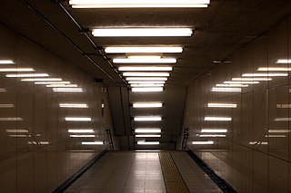
A fluorescent lamp, or fluorescent tube, is a low-pressure mercury-vapor gas-discharge lamp that uses fluorescence to produce visible light. An electric current in the gas excites mercury vapor, which produces short-wave ultraviolet light that then causes a phosphor coating on the inside of the lamp to glow. A fluorescent lamp converts electrical energy into useful light much more efficiently than an incandescent lamp. The typical luminous efficacy of fluorescent lighting systems is 50–100 lumens per watt, several times the efficacy of incandescent bulbs with comparable light output. For comparison, the luminous efficiency of an incandescent bulb may only be 16 lumens per watt.

<span class="mw-page-title-main">Cold cathode</span> Type of electrode and part of cold cathode fluorescent lamp.

A cold cathode is a cathode that is not electrically heated by a filament. A cathode may be considered "cold" if it emits more electrons than can be supplied by thermionic emission alone. It is used in gas-discharge lamps, such as neon lamps, discharge tubes, and some types of vacuum tube. The other type of cathode is a hot cathode, which is heated by electric current passing through a filament. A cold cathode does not necessarily operate at a low temperature: it is often heated to its operating temperature by other methods, such as the current passing from the cathode into the gas.

<span class="mw-page-title-main">Mains electricity</span> Type of lower-voltage electricity most commonly provided by utilities

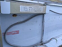
Mains electricity or utility power, grid power, domestic power, and wall power, or, in some parts of Canada, hydro, is a general-purpose alternating-current (AC) electric power supply. It is the form of electrical power that is delivered to homes and businesses through the electrical grid in many parts of the world. People use this electricity to power everyday items by plugging them into a wall outlet.

<span class="mw-page-title-main">Neon lamp</span> Light source based on gas discharge

A neon lamp is a miniature gas-discharge lamp. The lamp typically consists of a small glass capsule that contains a mixture of neon and other gases at a low pressure and two electrodes. When sufficient voltage is applied and sufficient current is supplied between the electrodes, the lamp produces an orange glow discharge. The glowing portion in the lamp is a thin region near the cathode; the larger and much longer neon signs are also glow discharges, but they use the positive column which is not present in the ordinary neon lamp. Neon glow lamps were widely used as indicator lamps in the displays of electronic instruments and appliances. They are still sometimes used for their electrical simplicity in high-voltage circuits.

An antifuse is an electrical device that performs the opposite function to a fuse. Whereas a fuse starts with a low resistance and is designed to permanently break or open an electrically conductive path, an antifuse starts with a high resistance--an open circuit--and programming it converts it into a permanent electrically conductive path. This technology has many applications. Antifuses are best known for their use in mini-light style low-voltage Christmas tree lights.

<span class="mw-page-title-main">Plasma globe</span> Decorative electrical device

A plasma ball, plasma globe, or plasma lamp is a clear glass container filled with noble gases, usually a mixture of neon, krypton, and xenon, that has a high-voltage electrode in the center of the container. When voltage is applied, a plasma is formed within the container. Plasma filaments extend from the inner electrode to the outer glass insulator, giving the appearance of multiple constant beams of colored light. Plasma balls were popular as novelty items in the 1980s.

<span class="mw-page-title-main">Hydrargyrum medium-arc iodide lamp</span>

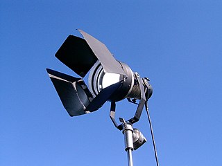
Hydrargyrum medium-arc iodide (HMI) is the trademark name of Osram's brand of metal-halide gas discharge medium arc-length lamp, made specifically for film and entertainment applications. Hydrargyrum comes from the Greek name for the element mercury.

<span class="mw-page-title-main">Electronic component</span> Discrete device in an electronic system

An electronic component is any basic discrete electronic device or physical entity part of an electronic system used to affect electrons or their associated fields. Electronic components are mostly industrial products, available in a singular form and are not to be confused with electrical elements, which are conceptual abstractions representing idealized electronic components and elements. A datasheet for an electronic component is a technical document that provides detailed information about the component's specifications, characteristics, and performance.

<span class="mw-page-title-main">Capacitor types</span> Manufacturing styles of an electronic device

Capacitors are manufactured in many styles, forms, dimensions, and from a large variety of materials. They all contain at least two electrical conductors, called plates, separated by an insulating layer (dielectric). Capacitors are widely used as parts of electrical circuits in many common electrical devices.

An induction heater is a key piece of equipment used in all forms of induction heating. Typically an induction heater operates at either medium frequency (MF) or radio frequency (RF) ranges.

Voltage optimisation is a term given to the systematic controlled reduction in the voltages received by an energy consumer to reduce energy use, power demand and reactive power demand. While some voltage 'optimisation' devices have a fixed voltage adjustment, others electronically regulate the voltage automatically.

<span class="mw-page-title-main">Applications of capacitors</span> Uses of capacitors in daily life

Capacitors have many uses in electronic and electrical systems. They are so ubiquitous that it is rare that an electrical product does not include at least one for some purpose. Capacitors allow only AC signals to pass when they are charged blocking DC signals. The main components of filters are capacitors. Capacitors have the ability to connect one circuit segment to another. Capacitors are used by Dynamic Random Access Memory (DRAM) devices to represent binary information as bits.

The Delco ignition system, also known as the Kettering ignition system, points and condenser ignition or breaker point ignition, is a type of inductive discharge ignition system invented by Charles F. Kettering. It was first sold commercially on the 1912 Cadillac and was manufactured by Delco. Over time, it was used extensively by all automobile and truck manufacturers on spark ignition, i.e., gasoline engines. Today it is still widely used in coil-on-plug, coil-near-plug and in coil packs in distributorless ignitions. An alternative system used in automobiles is capacitor discharge ignition, primarily found now as aftermarket upgrade systems. Electronic ignition was a common term for Kettering inductive ignition with the points replaced with an electronic switch such as a transistor.

<span class="mw-page-title-main">Noise generator</span> Circuit that produces electrical noise

A noise generator is a circuit that produces electrical noise. Noise generators are used to test signals for measuring noise figure, frequency response, and other parameters. Noise generators are also used for generating random numbers.

<span class="mw-page-title-main">Film capacitor</span> Electrical capacitor with an insulating plastic film as the dielectric

Film capacitors, plastic film capacitors, film dielectric capacitors, or polymer film capacitors, generically called film caps as well as power film capacitors, are electrical capacitors with an insulating plastic film as the dielectric, sometimes combined with paper as carrier of the electrodes.

IEC 61000-3-2Electromagnetic compatibility (EMC) – Part 3-2: Limits – Limits for harmonic current emissions is an international standard that limits mains voltage distortion by prescribing the maximum value for harmonic currents from the second harmonic up to and including the 40th harmonic current. IEC 61000-3-2 applies to equipment with a rated current up to 16 A – for equipment above 16 A see IEC 61000-3-12.

<span class="mw-page-title-main">Glow switch starter</span>

A glow switch starter or glowbottle starter is a type of preheat starter used with a fluorescent lamp. It is commonly filled with neon gas or argon gas and typically contains a bimetallic strip and a stationary electrode. The operating principle is simple, when current is applied, the gas inside ionizes and heats a bimetallic strip which in turn bends toward the stationary electrode thus shorting the starter between the electrodes of the fluorescent lamp. After about a second the starter's bimetallic strip cools and opens the circuit between the electrodes, and the process repeats until the lamp has lit. One disadvantage of glow switch starters is that when the lamp is at the end of its life it will continuously blink on and off until the glow switch starter wears out or an electrode on the fluorescent lamp burns out. Glow starters have a relatively short life, and light fittings enable the starter to be changed easily. Electronic starters, being interchangeable and using the same casing as a glow starter, last for many years.

References

  1. 1 2 3 Sinclair, Ian Robertson (2001). Sensors and transducers, 3rd Ed. Newnes. pp. 69–70. ISBN   978-0750649322.
  2. Kularatna, Nihal (1998). Power Electronics Design Handbook. Newnes. pp. 232–233. ISBN   978-0750670739.
  3. Aluf, Ofer (2012). Optoisolation Circuits: Nonlinearity Applications in Engineering. World Scientific. pp. 8–11. Bibcode:2012ocna.book.....A. ISBN   978-9814317009. This source uses the term "absolute negative differential resistance" to refer to active resistance
  4. "Understanding Transformer Noise" (PDF). federalpacific.com. Federal Pacific. Archived from the original (PDF) on 15 March 2015. Retrieved 8 August 2015.
  5. "infiNET dimmer datasheet" (PDF). Crestron Electronics, Inc. 9 March 2005. Retrieved 22 July 2013.
  6. 1 2 Specifier Reports: Electronic Ballasts p.18, National Lighting Product Information Program, Volume 8 Number 1, May 2000. Retrieved 13 May 2013.
  7. IES Lighting Handbook 1984
  8. "The City of Calgary - Streetlighting Digital Ballast pilot project". Archived from the original on 2013-07-29. Retrieved 2012-06-23.
  9. IEEE Std. 100 "Dictionary of IEEE Standards Terms, Standard 100", ISBN   0-7381-2601-2, page 83
  10. ANSI standard C82.13-2002 "Definitions for Fluorescent Lamp Ballasts", page 1
  11. "Ballast factor". Lawrence Berkeley National Laboratory. Archived from the original on March 19, 2013. Retrieved April 12, 2013.