Related Research Articles

An amplifier, electronic amplifier or (informally) amp is an electronic device that can increase the magnitude of a signal. It is a two-port electronic circuit that uses electric power from a power supply to increase the amplitude of a signal applied to its input terminals, producing a proportionally greater amplitude signal at its output. The amount of amplification provided by an amplifier is measured by its gain: the ratio of output voltage, current, or power to input. An amplifier is defined as a circuit that has a power gain greater than one.

Peripheral Component Interconnect (PCI) is a local computer bus for attaching hardware devices in a computer and is part of the PCI Local Bus standard. The PCI bus supports the functions found on a processor bus but in a standardized format that is independent of any given processor's native bus. Devices connected to the PCI bus appear to a bus master to be connected directly to its own bus and are assigned addresses in the processor's address space. It is a parallel bus, synchronous to a single bus clock. Attached devices can take either the form of an integrated circuit fitted onto the motherboard or an expansion card that fits into a slot. The PCI Local Bus was first implemented in IBM PC compatibles, where it displaced the combination of several slow Industry Standard Architecture (ISA) slots and one fast VESA Local Bus (VLB) slot as the bus configuration. It has subsequently been adopted for other computer types. Typical PCI cards used in PCs include: network cards, sound cards, modems, extra ports such as Universal Serial Bus (USB) or serial, TV tuner cards and hard disk drive host adapters. PCI video cards replaced ISA and VLB cards until rising bandwidth needs outgrew the abilities of PCI. The preferred interface for video cards then became Accelerated Graphics Port (AGP), a superset of PCI, before giving way to PCI Express.
Bridging loss is the loss, at a given frequency, that results when an impedance is connected across a transmission line. It is expressed as the ratio, in decibels, of the signal power delivered to a given point in a system downstream from the bridging point prior to bridging, to the signal power delivered to the given point after bridging. The term is introduced because return loss is not applicable to the high-impedance input conditions. The term is also used in telephone practice and synonymous with the insertion loss that result from bridging an impedance across a circuit.
In telecommunications, insertion loss is the loss of signal power resulting from the insertion of a device in a transmission line or optical fiber and is usually expressed in decibels (dB).
A passband is the range of frequencies or wavelengths that can pass through a filter. For example, a radio receiver contains a bandpass filter to select the frequency of the desired radio signal out of all the radio waves picked up by its antenna. The passband of a receiver is the range of frequencies it can receive when it is tuned into the desired frequency (channel).
In telecommunications, return loss is a measure in relative terms of the power of the signal reflected by a discontinuity in a transmission line or optical fiber. This discontinuity can be caused by a mismatch between the termination or load connected to the line and the characteristic impedance of the line. It is usually expressed as a ratio in decibels (dB);

In electronics, gain is a measure of the ability of a two-port circuit to increase the power or amplitude of a signal from the input to the output port by adding energy converted from some power supply to the signal. It is usually defined as the mean ratio of the signal amplitude or power at the output port to the amplitude or power at the input port. It is often expressed using the logarithmic decibel (dB) units. A gain greater than one, that is amplification, is the defining property of an active component or circuit, while a passive circuit will have a gain of less than one.
Loss may refer to:

A coaxial RF connector is an electrical connector designed to work at radio frequencies in the multi-megahertz range. RF connectors are typically used with coaxial cables and are designed to maintain the shielding that the coaxial design offers. Better models also minimize the change in transmission line impedance at the connection in order to reduce signal reflection and power loss. As the frequency increases, transmission line effects become more important, with small impedance variations from connectors causing the signal to reflect rather than pass through. An RF connector must not allow external signals into the circuit through electromagnetic interference and capacitive pickup.

In radio engineering, an antenna or aerial is the interface between radio waves propagating through space and electric currents moving in metal conductors, used with a transmitter or receiver. In transmission, a radio transmitter supplies an electric current to the antenna's terminals, and the antenna radiates the energy from the current as electromagnetic waves. In reception, an antenna intercepts some of the power of a radio wave in order to produce an electric current at its terminals, that is applied to a receiver to be amplified. Antennas are essential components of all radio equipment.

Effective radiated power (ERP), synonymous with equivalent radiated power, is an IEEE standardized definition of directional radio frequency (RF) power, such as that emitted by a radio transmitter. It is the total power in watts that would have to be radiated by a half-wave dipole antenna to give the same radiation intensity as the actual source antenna at a distant receiver located in the direction of the antenna's strongest beam. ERP measures the combination of the power emitted by the transmitter and the ability of the antenna to direct that power in a given direction. It is equal to the input power to the antenna multiplied by the gain of the antenna. It is used in electronics and telecommunications, particularly in broadcasting to quantify the apparent power of a broadcasting station experienced by listeners in its reception area.
A low-noise amplifier (LNA) is an electronic component that amplifies a very low-power signal without significantly degrading its signal-to-noise ratio (SNR). Any electronic amplifier will increase the power of both the signal and the noise present at its input, but the amplifier will also introduce some additional noise. LNAs are designed to minimize that additional noise, by choosing special components, operating points, and circuit topologies. Minimizing additional noise must balance with other design goals such as power gain and impedance matching.
This is an index of articles relating to electronics and electricity or natural electricity and things that run on electricity and things that use or conduct electricity.
A link budget is an accounting of all of the power gains and losses that a communication signal experiences in a telecommunication system; from a transmitter, through a communication medium such as radio waves, cable, waveguide, or optical fiber, to the receiver. It is an equation giving the received power from the transmitter power, after the attenuation of the transmitted signal due to propagation, as well as the antenna gains and feedline and other losses, and amplification of the signal in the receiver or any repeaters it passes through. A link budget is a design aid, calculated during the design of a communication system to determine the received power, to ensure that the information is received intelligibly with an adequate signal-to-noise ratio. Randomly varying channel gains such as fading are taken into account by adding some margin depending on the anticipated severity of its effects. The amount of margin required can be reduced by the use of mitigating techniques such as antenna diversity or frequency hopping.

An RF switch or microwave switch is a device to route high frequency signals through transmission paths. RF and microwave switches are used extensively in microwave test systems for signal routing between instruments and devices under test (DUT). Incorporating a switch into a switch matrix system enables you to route signals from multiple instruments to single or multiple DUTs. This allows multiple tests to be performed with the same setup, eliminating the need for frequent connects and disconnects. The entire testing process can be automated, increasing the throughput in high-volume production environments.
Scattering parameters or S-parameters describe the electrical behavior of linear electrical networks when undergoing various steady state stimuli by electrical signals.

An attenuator is an electronic device that reduces the power of a signal without appreciably distorting its waveform.
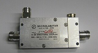
Power dividers and directional couplers are passive devices used mostly in the field of radio technology. They couple a defined amount of the electromagnetic power in a transmission line to a port enabling the signal to be used in another circuit. An essential feature of directional couplers is that they only couple power flowing in one direction. Power entering the output port is coupled to the isolated port but not to the coupled port. A directional coupler designed to split power equally between two ports is called a hybrid coupler.
In copper twisted pair wire networks, copper cable certification is achieved through a thorough series of tests in accordance with Telecommunications Industry Association (TIA) or International Organization for Standardization (ISO) standards. These tests are done using a certification-testing tool, which provide pass or fail information. While certification can be performed by the owner of the network, certification is primarily done by datacom contractors. It is this certification that allows the contractors to warranty their work.
Mismatch loss in transmission line theory is the amount of power expressed in decibels that will not be available on the output due to impedance mismatches and signal reflections. A transmission line that is properly terminated, that is, terminated with the same impedance as that of the characteristic impedance of the transmission line, will have no reflections and therefore no mismatch loss. Mismatch loss represents the amount of power wasted in the system. It can also be thought of as the amount of power gained if the system was perfectly matched. Impedance matching is an important part of RF system design; however, in practice there will likely be some degree of mismatch loss. In real systems, relatively little loss is due to mismatch loss and is often on the order of 1dB.
References
- ↑ "Insertion Loss / Return Loss". 19 April 2017.
![]() This article incorporates public domain material from Federal Standard 1037C. General Services Administration. (in support of MIL-STD-188).
This article incorporates public domain material from Federal Standard 1037C. General Services Administration. (in support of MIL-STD-188).
| | This article related to telecommunications is a stub. You can help Wikipedia by expanding it. |