Null modem

Last updated
A null modem adapter Null modem.jpg
A null modem adapter

Null modem is a communication method to directly connect two DTEs (computer, terminal, printer, etc.) using an RS-232 serial cable. The name stems from the historical use of RS-232 cables to connect two teleprinter devices or two modems in order to communicate with one another; null modem communication refers to using a crossed-over RS-232 cable to connect the teleprinters directly to one another without the modems. It is also used to serially connect a computer to a printer, since both are DTE, and is known as a Printer Cable.

Contents

The RS-232 standard is asymmetric as to the definitions of the two ends of the communications link, assuming that one end is a DTE and the other is a DCE, e.g. a modem. With a null modem connection the transmit and receive lines are crosslinked. Depending on the purpose, sometimes also one or more handshake lines are crosslinked. Several wiring layouts are in use because the null modem connection is not covered by the RS-232 standard.

Origins

Originally, the RS-232 standard was developed and used for teleprinter machines which could communicate with each other over phone lines. Each teleprinter would be physically connected to its modem via an RS-232 connection and the modems could call each other to establish a remote connection between the teleprinters. If a user wished to connect two teleprinters directly without modems (null modem) then they would crosslink the connections. The term null modem may also refer to the cable or adapter itself as well as the connection method. [1] Null modem cables were a popular method for transferring data between the early personal computers from the 1980s to the early 1990s.

Cables and adapters

A null modem cable Null modem cable 1.jpg
A null modem cable

A null modem cable is a RS-232 serial cable where the transmit and receive lines are crosslinked. In some cables there are also handshake lines crosslinked. In many situations a straight-through serial cable is used, together with a null modem adapter. The adapter contains the necessary crosslinks between the signals. [2] [3]

Wiring diagrams

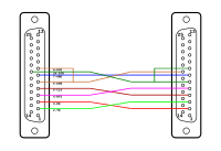
DB-25 null modem wiring diagram D25 Null Modem Wiring.png
DB-25 null modem wiring diagram
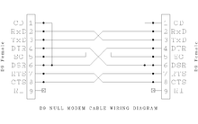
DE-9 null modem wiring diagram D9 Null Modem Wiring.png
DE-9 null modem wiring diagram

Below is a very common wiring diagram for a null modem cable to interconnect two DTEs (e.g. two PCs) providing full handshaking, which works with software relying on proper assertion of the Data Carrier Detect (DCD) signal: [2]

One sideSignal
direction
Other side
Signal and abbreviations DB-25 pin DE-9 pinDE-9 pinDB-25 pinSignal
Frame Ground FG1Common1FG
Transmitted Data TxD, TD2323RxD
Received Data RxD, RD3232TxD
Request To Send RTS4785CTS
Clear To Send CTS5874RTS
Signal Ground SG75Common57SG
Data Set Ready DSR66420DTR
Data Carrier Detect DCD, CD81
Data Terminal Ready DTR20418DCD
66DSR

Applications

The original application of a null modem was to connect two teleprinter terminals directly without using modems. As the RS-232 standard was adopted by other types of equipment, designers needed to decide whether their devices would have DTE-like or DCE-like interfaces. When an application required that two DTEs (or two DCEs) needed to communicate with each other, then a null modem was necessary. [4]

Null modems were commonly used for file transfer between computers, or remote operation. Under the Microsoft Windows operating system, the direct cable connection can be used over a null modem connection. The later versions of MS-DOS were shipped with the InterLnk program. Both pieces of software allow the mapping of a hard disk on one computer as a network drive on the other computer. No Ethernet hardware (such as a network interface card or a modem) is required for this. [5] On the Amiga computer, a null modem connection was a common way of playing multiplayer games between two machines.

The popularity and availability of faster information exchange systems such as Ethernet made the use of null modem cables less common. In modern systems, such a cable can still be useful for kernel mode development, since it allows the user to remotely debug a kernel with a minimum of device drivers and code (a serial driver mainly consists of two FIFO buffers and an interrupt service routine). KGDB for Linux, ddb for BSD, and WinDbg or KD for Windows can be used to remotely debug systems, for example. This can also provide a serial console through which the in-kernel debugger can be dropped to in case of kernel panics, in which case the local monitor and keyboard may not be usable anymore (the GUI reserves those resources and dropping to the debugger in the case of a panic won't free them).

Another context where these cables can be useful is when administering "headless" devices providing a serial administration console (i.e. managed switches, rackmount server units, and various embedded systems). An example of embedded systems that widely use null modems for remote monitoring include RTUs, device controllers, and smart sensing devices. These devices tend to reside in close proximity and lend themselves to short run serial communication through protocols such as DNP3, Modbus, and other IEC variants. The Electric, Oil, Gas, and Water Utilities are slow to respond to newer networking technologies which may be due to large investments in capital equipment that has useful service life measured in decades. Serial ports and null modem cables are still widely used in these industries with Ethernet just slowly becoming a widely available option.

Types of null modem

Connecting two DTE devices together requires a null modem that acts as a DCE between the devices by swapping the corresponding signals (TD-RD, DTR-DSR, and RTS-CTS). This can be done with a separate device and two cables, or using a cable wired to do this. If devices require Carrier Detect, it can be simulated by connecting DSR and DCD internally in the connector, thus obtaining CD from the remote DTR signal. One feature of the Yost standard is that a null modem cable is a "rollover cable" that just reverses pins 1 through 8 on one end to 8 through 1 on the other end. [1]

No hardware handshaking

Null modem xon-xoff.svg
Null modem DB-9 xon-xoff.svg
Wiring pinouts for DB-25 (left) and DE-9 (right) connectors

The simplest type of serial cable has no hardware handshaking. This cable has only the data and signal ground wires connected. All of the other pins have no connection. With this type of cable flow control has to be implemented in the software. The use of this cable is restricted to data-traffic only on its cross-connected Rx and Tx lines. This cable can also be used in devices that do not need or make use of modem control signals. [1]

Loopback handshaking

Null modem 3-wire.svg
Null modem DB-9 3-wire.svg
Wiring pinouts for DB-25 (left) and DE-9 (right) connectors

Because of the compatibility issues and potential problems with a simple null modem cable, a solution was developed to trick the software into thinking there was handshaking available. However, the cable pin out merely loops back, and does not physically support the hardware flow control. [1]

This cable could be used with more software but it had no actual enhancements over its predecessor. The software would work thinking it had hardware flow control but could suddenly stop when higher speeds were reached and with no identifiable reason.

Partial handshaking

Null modem 5-wire.svg
Null modem DB-9 5-wire.svg
Wiring pinouts for DB-25 (left) and DE-9 (right) connectors

In this cable the flow control lines are still looped back to the device. However, they are done so in a way that still permits Request To Send (RTS) and Clear To Send (CTS) flow control but has no actual functionality. The only way the flow control signal would reach the other device is if the opposite device checked for a Carrier Detect (CD) signal (at pin 1 on a DE-9 cable and pin 8 on a DB-25 cable). As a result, only specially designed software could make use of this partial handshaking. Software flow control still worked with this cable. [1]

Full handshaking

Null modem 7-wire.svg
Null modem DB-9 7-wire.svg
Wiring pinouts for DB-25 (left) and DE-9 (right) connectors

This cable is incompatible with the previous types of cables' hardware flow control, due to a crossing of its RTS/CTS pins. With suitable software, the cable is capable of much higher speeds than its predecessors. It also supports software flow control. [1]

Virtual null modem

A virtual null modem is a communication method to connect two computer applications directly using a virtual serial port. Unlike a null modem cable, a virtual null modem is a software solution which emulates a hardware null modem within the computer. [6] [7] All features of a hardware null modem are available in a virtual null modem as well. There are some advantages to this:

For instance, DOSBox has allowed older DOS games to use virtual null modems.

Another common example consists of Unix pseudoterminals (pty) which present a standard tty interface to user applications, including virtual serial controls. Two such ptys may easily be linked together by an application to form a virtual null modem communication path.

See also

Related Research Articles

<span class="mw-page-title-main">RS-232</span> Standard for serial communication

In telecommunications, RS-232 or Recommended Standard 232 is a standard originally introduced in 1960 for serial communication transmission of data. It formally defines signals connecting between a DTE such as a computer terminal, and a DCE, such as a modem. The standard defines the electrical characteristics and timing of signals, the meaning of signals, and the physical size and pinout of connectors. The current version of the standard is TIA-232-F Interface Between Data Terminal Equipment and Data Circuit-Terminating Equipment Employing Serial Binary Data Interchange, issued in 1997. The RS-232 standard had been commonly used in computer serial ports and is still widely used in industrial communication devices.

<span class="mw-page-title-main">Data circuit-terminating equipment</span> Communications system component

A data circuit-terminating equipment (DCE) is a device that sits between the data terminal equipment (DTE) and a data transmission circuit. It is also called data communication(s) equipment and data carrier equipment. Usually, the DTE device is the terminal, and the DCE is a modem.

<span class="mw-page-title-main">Data terminal equipment</span> Communications system equipment

Data terminal equipment (DTE) is an end instrument that converts user information into signals or reconverts received signals. It is also called data processing terminal equipment or tail circuit. A DTE device communicates with the data circuit-terminating equipment (DCE), such as a modem. The DTE/DCE classification was introduced by IBM.

<span class="mw-page-title-main">Universal asynchronous receiver-transmitter</span> Computer hardware device

A universal asynchronous receiver-transmitter is a computer hardware device for asynchronous serial communication in which the data format and transmission speeds are configurable. It sends data bits one by one, from the least significant to the most significant, framed by start and stop bits so that precise timing is handled by the communication channel. The electric signaling levels are handled by a driver circuit external to the UART. Common signal levels are RS-232, RS-485, and raw TTL for short debugging links. Early teletypewriters used current loops.

<span class="mw-page-title-main">Serial port</span> Communication interface transmitting information sequentially

On computers, a serial port is a serial communication interface through which information transfers in or out sequentially one bit at a time. This is in contrast to a parallel port, which communicates multiple bits simultaneously in parallel. Throughout most of the history of personal computers, data has been transferred through serial ports to devices such as modems, terminals, various peripherals, and directly between computers.

Loopback is the routing of electronic signals or digital data streams back to their source without intentional processing or modification. It is primarily a means of testing the communications infrastructure.

GeoPort is a serial data system used on some models of the Apple Macintosh that could be externally clocked to run at a 2 megabit per second data rate. GeoPort slightly modified the existing Mac serial port pins to allow the computer's internal DSP hardware or software to send data that, when passed to a digital-to-analog converter, emulated various devices such as modems and fax machines. GeoPort could be found on late-model 68K-based machines as well as many pre-USB Power Macintosh models and PiPPiN. Some later Macintosh models also included an internal GeoPort via an internal connector on the Communications Slot. Apple GeoPort technology is now obsolete, and modem support is typically offered through USB.

<span class="mw-page-title-main">RS-422</span> Standard for serial communication

RS-422, also known as TIA/EIA-422, is a technical standard originated by the Electronic Industries Alliance, first issued in 1975, that specifies electrical characteristics of a digital signaling circuit. It was meant to be the foundation of a suite of standards that would replace the older RS-232C standard with standards that offered much higher speed, better immunity from noise, and longer cable lengths. RS-422 systems can transmit data at rates as high as 10 Mbit/s, or may be sent on cables as long as 1,200 meters (3,900 ft) at lower rates. It is closely related to RS-423, which uses the same signaling systems but on a different wiring arrangement.

The Parallel Line Internet Protocol (PLIP) is a computer networking protocol for direct computer-to-computer communications using the parallel port normally used for connections to a printer.

<span class="mw-page-title-main">Crossover cable</span> Cable with intentionally crossed wiring

A crossover cable connects two devices of the same type, for example DTE-DTE or DCE-DCE, usually connected asymmetrically (DTE-DCE), by a modified cable called a crosslink. Such a distinction between devices was introduced by IBM.

In data communications, flow control is the process of managing the rate of data transmission between two nodes to prevent a fast sender from overwhelming a slow receiver. Flow control should be distinguished from congestion control, which is used for controlling the flow of data when congestion has actually occurred. Flow control mechanisms can be classified by whether or not the receiving node sends feedback to the sending node.

<span class="mw-page-title-main">Serial cable</span> Networking cable used for serial communication

A serial cable is a cable used to transfer information between two devices using a serial communication protocol. The form of connectors depends on the particular serial port used. A cable wired for connecting two DTEs directly is known as a null modem cable.

<span class="mw-page-title-main">Computer port (hardware)</span> Computer hardware

In computer hardware, a port serves as an interface between the computer and other computers or peripheral devices. In computer terms, a port generally refers to the part of a computing device available for connection to peripherals such as input and output devices. Computer ports have many uses, to connect a monitor, webcam, speakers, or other peripheral devices. On the physical layer, a computer port is a specialized outlet on a piece of equipment to which a plug or cable connects. Electronically, the several conductors where the port and cable contacts connect, provide a method to transfer signals between devices.

<span class="mw-page-title-main">Modified Modular Jack</span> Serial port connector type

The Modified Modular Jack (MMJ) is a small form-factor serial port connector developed by Digital Equipment Corporation (DEC). It uses a modified version of the 6P6C modular connector with the latch displaced off-center so standard modular connectors found on Ethernet cables or phone jacks cannot accidentally be plugged in. MMJ connections are used on Digital minicomputers, such as the PDP-11, VAX and Alpha systems, and to connect terminals, printers, and serial console servers.

RS-423, also known as TIA/EIA-423, is a technical standard originated by the Electronic Industries Alliance that specifies electrical characteristics of a digital signaling circuit. Although it was originally intended as a successor to RS-232C offering greater cable lengths, it is not widely used.

Data Carrier Detect (DCD) or Carrier Detect (CD) is a control signal present inside an RS-232 serial communications cable that goes between a computer and another device, such as a modem. This signal is a simple "high/low" status bit that is sent from a data communications equipment (DCE) to a data terminal equipment (DTE), i.e., from the modem or other peripheral to a computer in a typical scenario. It is present on virtually all PC serial ports - pin 1 of a nine-pin (DE9) serial port, or pin eight over a 25-pin (DB25) port. Its purpose varies depending on the device connected, but the most specific meaning is to indicate when a modem is connected to another remote modem via telephone lines.

<span class="mw-page-title-main">Modem</span> Device that modulates an analog carrier signal to encode digital information

A modulator-demodulator or modem is a computer hardware device that converts data from a digital format into a format suitable for an analog transmission medium such as telephone or radio. A modem transmits data by modulating one or more carrier wave signals to encode digital information, while the receiver demodulates the signal to recreate the original digital information. The goal is to produce a signal that can be transmitted easily and decoded reliably. Modems can be used with almost any means of transmitting analog signals, from light-emitting diodes to radio.

Data Terminal Ready (DTR) is a control signal in RS-232 serial communications, transmitted from data terminal equipment (DTE), such as a computer, to data communications equipment (DCE), for example a modem, to indicate that the terminal is ready for communications and the modem may initiate a communications channel.

Commodore 64 disk/tape emulation and data transfer comprises hardware and software for Commodore 64 disk & tape emulation and for data transfer between either Commodore 64 (C64), Commodore (1541) disk drive or Commodore tape deck and newer computers.

In telecommunications, RS-366, later known as EIA-366, defines a standard for serial communications between computers and an auto dialer, which is used to dial telephones. It was intended to be used to automate the operation of modems. The standard uses the same DB25 connectors and electrical signalling standards of the well-known RS-232 standard, which RS-366 was designed to support. The CCITT had a matching standard, V.25.

References

  1. 1 2 3 4 5 6 Lammert Bies. "RS232 serial null modem cable wiring and tutorial". lammertbies.nl. Retrieved 2013-12-26.
  2. 1 2 "Null Modem". nullmodem.com. 2008-11-07. Retrieved 2013-12-26.
  3. "Nullmodem (9-9) - HwB". hardwarebook.info. 2006-12-27. Retrieved 2013-12-26.
  4. "ADTPro - ADTPro Serial Cabling". sourceforge.net. 2011-01-25. Retrieved 2013-12-26.
  5. "MS-DOS External commands - INTERLNK". angelfire.com. Retrieved 2013-12-26.
  6. "Null-modem emulator | Download Null-modem emulator software for free at". sourceforge.net. Retrieved 2013-12-26.
  7. "BerliOS Developer: Project Summary - N8VB_vCOM Virtual Null Modem Cable". berlios.de. 2005-07-15. Archived from the original on 2013-12-26. Retrieved 2013-12-26.