This article's lead sectionmay be too short to adequately summarize the key points. Please consider expanding the lead to provide an accessible overview of all important aspects of the article.(January 2022)
Serial ATA industry compatibility specifications originate from the Serial ATA International Organization (SATA-IO) which are then released by the INCITS Technical Committee T13, AT Attachment (INCITS T13).[3]
SATA was announced in 2000[4][5] in order to provide several advantages over the earlier PATA interface such as reduced cable size and cost (seven conductors instead of 40 or 80), native hot swapping, faster data transfer through higher signaling rates, and more efficient transfer through an (optional) I/O queuing protocol. Revision 1.0 of the specification was released in January 2003.[2]
Serial ATA industry compatibility specifications originate from the Serial ATA International Organization (SATA-IO). The SATA-IO group collaboratively creates, reviews, ratifies, and publishes the interoperability specifications, the test cases and plugfests. As with many other industry compatibility standards, the SATA content ownership is transferred to other industry bodies: primarily INCITS T13[3] and an INCITS T10 subcommittee (SCSI), a subgroup of T10 responsible for Serial Attached SCSI (SAS). The remainder of this article strives to use the SATA-IO terminology and specifications.
Before SATA's introduction in 2000, PATA was simply known as ATA. The "AT Attachment" (ATA) name originated after the 1984 release of the IBM Personal Computer AT, more commonly known as the IBM AT.[6] The IBM AT's controller interface became a de facto industry interface for the inclusion of hard disks. "AT" was IBM's abbreviation for "Advanced Technology"; thus, many companies and organizations indicate SATA is an abbreviation of "Serial Advanced Technology Attachment". However, the ATA specifications simply use the name "AT Attachment", to avoid possible trademark issues with IBM.[7]
SATA host adapters and devices communicate via a high-speed serial cable over two pairs of conductors. In contrast, parallel ATA (the redesignation for the legacy ATA specifications) uses a 16-bit wide data bus with many additional support and control signals, all operating at a much lower frequency. To ensure backward compatibility with legacy ATA software and applications, SATA uses the same basic ATA and ATAPI command sets as legacy ATA devices.
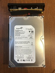
The world's first SATA hard disk drive is the Seagate Barracuda SATA V, which was released in Jan 2003.[8]
SATA has replaced parallel ATA in consumer desktop and laptop computers; SATA's market share in the desktop PC market was 99% in 2008.[9] PATA has mostly been replaced by SATA for any use; with PATA in declining use in industrial and embedded applications that use CompactFlash (CF) storage, which was designed around the legacy PATA standard. A 2008 standard, CFast, to replace CompactFlash is based on SATA.[10][11]
Features
SATA 6Gbit/s host controller, a PCI Express ×1 card with Marvell chipset
Hot plug
The Serial ATA spec requires SATA devices be capable of hot plugging; that is, devices that meet the specification are capable of insertion or removal of a device into or from a backplane connector (combined signal and power) that has power on. After insertion, the device initializes and then operates normally. Depending upon the operating system, the host may also initialize, resulting in a hot swap. The powered host and device do not need to be in an idle state for safe insertion and removal, although unwritten data may be lost when power is removed.
Unlike PATA, both SATA and eSATA support hot plugging by design. However, this feature requires proper support at the host, device (drive), and operating-system levels. In general, SATA devices fulfill the device-side hot-plugging requirements, and most SATA host adapters support this function.[1]
For eSATA, hot plugging is supported in AHCI mode only. IDE mode does not support hot plugging.[12]
Advanced Host Controller Interface
Advanced Host Controller Interface (AHCI) is an open host controller interface published and used by Intel, which has become a de facto standard. It allows the use of advanced features of SATA such as hotplug and native command queuing (NCQ). If AHCI is not enabled by the motherboard and chipset, SATA controllers typically operate in "IDE[lower-alpha 2] emulation" mode, which does not allow access to device features not supported by the ATA (also called IDE) standard.
Windows device drivers that are labeled as SATA are often running in IDE emulation mode unless they explicitly state that they are AHCI mode, in RAID mode, or a mode provided by a proprietary driver and command set that allowed access to SATA's advanced features before AHCI became popular. Modern versions of Microsoft Windows, Mac OS X, FreeBSD, Linux with version 2.6.19 onward,[13] as well as Solaris and OpenSolaris, include support for AHCI, but earlier operating systems such as Windows XP do not. Even in those instances, a proprietary driver may have been created for a specific chipset, such as Intel's.[14]
Revisions
SATA revisions are typically designated with a dash followed by Roman numerals, e.g. "SATA-III",[15] to avoid confusion with the speed, which is always displayed in Arabic numerals, e.g. "SATA 6 Gbit/s". The speeds given are the raw interface rate in Gbit/s including line code overhead, and the usable data rate in MB/s without overhead.
SATA revision 1.0 (1.5Gbit/s, 150MB/s, Serial ATA-150)
Revision 1.0a[2] was released on January 7, 2003. First-generation SATA interfaces, now known as SATA 1.5Gbit/s, communicate at a rate of 1.5Gbit/s,[lower-alpha 3] and do not support Native Command Queuing (NCQ). Taking 8b/10b encoding overhead into account, they have an actual uncoded transfer rate of 1.2Gbit/s (150MB/s). The theoretical burst throughput of SATA 1.5Gbit/s is similar to that of PATA/133, but newer SATA devices offer enhancements such as NCQ, which improve performance in a multitasking environment.
During the initial period after SATA 1.5Gbit/s finalization, adapter and drive manufacturers used a "bridge chip" to convert existing PATA designs for use with the SATA interface. Bridged drives have a SATA connector, may include either or both kinds of power connectors, and, in general, perform identically to their native-SATA equivalents.[16]
As of April2010[update], the fastest 10,000rpm SATA hard disk drives could transfer data at maximum (not average) rates of up to 157MB/s,[17] which is beyond the capabilities of the older PATA/133 specification and also exceeds the capabilities of SATA 1.5Gbit/s.
SATA revision 2.0 (3Gbit/s, 300MB/s, Serial ATA-300)
SATA 2 connectors on a computer motherboard, all but two with cables plugged in. Note that there is no visible difference, other than the labeling, between SATA 1, SATA 2, and SATA 3 cables and connectors.
SATA revision 2.0 was released in April 2004, introducing Native Command Queuing (NCQ). It is backward compatible with SATA 1.5Gbit/s.[18]
Second-generation SATA interfaces run with a native transfer rate of 3.0Gbit/s that, when accounted for the 8b/10b encoding scheme, equals to the maximum uncoded transfer rate of 2.4Gbit/s (300MB/s). The theoretical burst throughput of the SATA revision 2.0, which is also known as the SATA 3Gbit/s, doubles the throughput of SATA revision 1.0.
All SATA data cables meeting the SATA spec are rated for 3.0Gbit/s and handle modern mechanical drives without any loss of sustained and burst data transfer performance. However, high-performance flash-based drives can exceed the SATA 3Gbit/s transfer rate; this is addressed with the SATA 6Gbit/s interoperability standard.
SATA revision 2.5
Announced in August 2005, SATA revision 2.5 consolidated the specification to a single document.[19][20]
SATA revision 2.6
Announced in February 2007, SATA revision 2.6 introduced the following features:[21]
Enhancements for robust reception of the Signature FIS.
SATA revision 3.0 (6Gbit/s, 600MB/s, Serial ATA-600)
Serial ATA International Organization (SATA-IO) presented the draft specification of SATA 6Gbit/s physical layer in July 2008,[22] and ratified its physical layer specification on August 18, 2008.[23] The full 3.0 standard was released on May 27, 2009.[24]
Third-generation SATA interfaces run with a native transfer rate of 6.0Gbit/s; taking 8b/10b encoding into account, the maximum uncoded transfer rate is 4.8Gbit/s (600MB/s). The theoretical burst throughput of SATA 6.0Gbit/s is double that of SATA revision 2.0. It is backward compatible with earlier SATA implementations.[22]
The SATA3.0 specification contains the following changes:
6Gbit/s for scalable performance.
Continued compatibility with SAS, including SAS 6Gbit/s, as per "a SAS domain may support attachment to and control of unmodified SATA devices connected directly into the SAS domain using the Serial ATA Tunneled Protocol (STP)" from the SATA Revision 3.0 Gold specification.
Isochronous Native Command Queuing (NCQ) streaming command to enable isochronous quality of service data transfers for streaming digital content applications.
An NCQ management feature that helps optimize performance by enabling host processing and management of outstanding NCQ commands.
Improved power management capabilities.
A small low insertion force (LIF) connector for more compact 1.8-inch storage devices.
A 7mm optical disk drive profile for the slimline SATA connector (in addition to the existing 12.7mm and 9.5mm profiles).
In general, the enhancements are aimed at improving quality of service for video streaming and high-priority interrupts. In addition, the standard continues to support distances up to one meter. The newer speeds may require higher power consumption for supporting chips, though improved process technologies and power management techniques may mitigate this. The later specification can use existing SATA cables and connectors, though it was reported in 2008 that some OEMs were expected to upgrade host connectors for the higher speeds.[25]
SATA revision 3.1
Released in July 2011, SATA revision 3.1 introduced or changed the following features:[26][27]
mSATA, for solid-state drives in mobile computing devices, a PCI Express Mini Card-like connector that is electrically SATA.[28] The connector was also used in some desktop computers, such as certain HP business PCs.[29]
Zero-power optical disk drive, a SATA optical drive that draws no power when idle.
Queued TRIM Command, improves solid-state drive performance.
Required Link Power Management, reduces overall system power demand of several SATA devices.
Hardware Control Features, enable host identification of device capabilities.
Universal Storage Module (USM), a new standard for cableless plug-in (slot) powered storage for consumer electronics devices.[30][31]
SATA revision 3.2
Released in August 2013, SATA revision 3.2 introduced the following features:[32]
The SATA Express specification defines an interface that combines both SATA and PCI Express buses, making it possible for both types of storage devices to coexist. By employing PCI Express, a much higher theoretical throughput of 1969MB/s is possible.[33][34]
The SATA M.2 standard is a small form factor implementation of the SATA Express interface, with the addition of an internal USB 3.0 port; see the M.2 (NGFF) section below for a more detailed summary.[35]
microSSD introduces a ball grid array electrical interface for miniaturized, embedded SATA storage.[36]
USM Slim reduces thickness of Universal Storage Module (USM) from 14.5 millimeters (0.57 inches) to 9 millimeters (0.35 inches).[37]
DevSleep enables lower power consumption for always-on devices while they are in low-power modes such as InstantGo (which used to be known as Connected Standby).[38]
Released in February 2016, SATA revision 3.3 introduced the following features:[41][42]
Shingled magnetic recording (SMR) support that provides a 25 percent or greater increase in hard disk drive capacity by overlapping tracks on the media.
Power Disable feature (see PWDIS pin) allows for remote power cycling of SATA drives and a Rebuild Assist function that speeds up the rebuild process to help ease maintenance in the data center.
Transmitter Emphasis Specification increases interoperability and reliability between host and devices in electrically demanding environments.
An activity indicator and staggered spin-up can be controlled by the same pin, adding flexibility and providing users with more choices.
The new Power Disable feature (similar to the SAS Power Disable feature) uses Pin 3 of the SATA power connector. Some legacy power supplies that provide 3.3 V power on Pin 3 would force drives with Power Disable feature to get stuck in a hard reset condition preventing them from spinning up. The problem can usually be eliminated by using a simple “Molex to SATA” power adaptor to supply power to these drives.[43]
SATA revision 3.4
Released in June 2018, SATA revision 3.4 introduced the following features that enable monitoring of device conditions and execution of housekeeping tasks, both with minimal impact on performance:[44]
Durable/Ordered Write Notification: enables writing selected critical cache data to the media, minimizing impact on normal operations.
Device Temperature Monitoring: allows for active monitoring of SATA device temperature and other conditions without impacting normal operation by utilizing the SFF-8609 standard for out-of-band (OOB) communications.
Device Sleep Signal Timing: provides additional definition to enhance compatibility between manufacturers’ implementations.
SATA revision 3.5
Released in July 2020, SATA revision 3.5 Introduces features that enable increased performance benefits and promote greater integration of SATA devices and products with other industry I/O standards:[45]
Device Transmit Emphasis for Gen 3 PHY: aligns SATA with other characteristics of other I/O measurement solutions to help SATA-IO members with testing and integration.
Defined Ordered NCQ Commands: allows the host to specify the processing relationships among queued commands and sets the order in which commands are processed in the queue.
Command Duration Limit Features: reduces latency by allowing the host to define quality of service categories, giving the host more granularity in controlling command properties. The feature helps align SATA with the "Fast Fail" requirements established by the Open Compute Project (OCP) and specified in the INCITS T13 Technical Committee standard.
Cables, connectors, and ports
2.5-inch SATA drive on top of a 3.5-inch SATA drive, close-up of data and power connectors. Also visible are 8 jumper pins on the 3.5-inch drive.
Connectors and cables present the most visible differences between SATA and parallel ATA drives. Unlike PATA, the same connectors are used on 3.5-inch SATA hard disks (for desktop and server computers) and 2.5-inch disks (for portable or small computers).[46]
Standard SATA connectors for both data and power have a conductor pitch of 1.27mm (0.050 inches). Low insertion force is required to mate a SATA connector. A smaller mini-SATA or mSATA connector is used by smaller devices such as 1.8-inch SATA drives, some DVD and Blu-ray drives, and mini SSDs.[47]
A special eSATA connector is specified for external devices, and an optionally implemented provision for clips to hold internal connectors firmly in place. SATA drives may be plugged into SAS controllers and communicate on the same physical cable as native SAS disks, but SATA controllers cannot handle SAS disks.
Female SATA ports (on motherboards for example) are for use with SATA data cables that have locks or clips to prevent accidental unplugging. Some SATA cables have right- or left-angled connectors to ease connection to circuit boards.
The SATA standard defines a data cable with seven conductors (three grounds and four active data lines in two pairs) and 8mm wide wafer connectors on each end. SATA cables can have lengths up to 1 meter (3.3ft), and connect one motherboard socket to one hard drive. PATA ribbon cables, in comparison, connect one motherboard socket to one or two hard drives, carry either 40 or 80 wires, and are limited to 45 centimeters (18in) in length by the PATA specification; however, cables up to 90 centimeters (35in) are readily available. Thus, SATA connectors and cables are easier to fit in closed spaces and reduce obstructions to air cooling. Some cables even include a locking feature, whereby a small (usually metal) spring holds the plug in the socket.
SATA connectors may be straight, right-angled, or left-angled. Angled connectors allow lower-profile connections. Right-angled (also called 90-degree) connectors lead the cable immediately away from the drive, on the circuit-board side. Left-angled (also called 270-degree) connectors lead the cable across the drive towards its top.
One of the problems associated with the transmission of data at high speed over electrical connections is described as noise, which is due to electrical coupling between data circuits and other circuits. As a result, the data circuits can both affect other circuits and be affected by them. Designers use a number of techniques to reduce the undesirable effects of such unintentional coupling. One such technique used in SATA links is differential signaling. This is an enhancement over PATA, which uses single-ended signaling. The use of fully shielded, dual coax conductors, with multiple ground connections, for each differential pair[49] improves isolation between the channels and reduces the chances of lost data in difficult electrical environments.
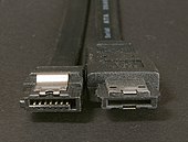
A seven-pin SATA data cable (left-angled version of the connector)
SATA connectors on 2.5 and 3.5-inch hard drives, with data pins on the left and power pins on the right. The two different pin lengths ensure a specific mating order; the longer lengths are ground pins and make contact first. (The cable side has similar variations to achieve three levels of mating order.)
SATA cable showing the two foil shielded differential pairs
Power connectors
Standard connector
Standard connector, power segment
Pin #
Mating
Function
—
Coding notch
1
3rd
3.3V power
2
3rd
3
2nd
Enter/exit Power Disable (PWDIS) mode (3.3V power, pre-charge prior to SATA 3.3)
4
1st
Ground
5
2nd
6
2nd
7
2nd
5V power, pre-charge
8
3rd
5V power
9
3rd
10
2nd
Ground
11
3rd
Staggered spinup / activity signal / direct head unload / vendor specific
12
1st
Ground
13
2nd
12V power, pre-charge
14
3rd
12V power
15
3rd
A fifteen-pin SATA power connector (This particular connector is missing the orange 3.3V wire.)
SATA specifies a different power connector than the four-pin Molex connector used on Parallel ATA (PATA) devices (and earlier small storage devices, going back to ST-506 hard disk drives and even to floppy disk drives that predated the IBM PC). It is a wafer-type connector, like the SATA data connector, but much wider (fifteen pins versus seven) to avoid confusion between the two. Some early SATA drives included the four-pin Molex power connector together with the new fifteen-pin connector, but most SATA drives now have only the latter.
The new SATA power connector contains many more pins for several reasons:[50]
3.3V is supplied along with the traditional 5V and 12V supplies. However, very few drives actually use it.
Pin 3 in SATA revision 3.3 has been redefined as PWDIS and is used to enter and exit the POWER DISABLE mode in line with SAS-3.[51] If Pin 3 is driven HIGH (2.1–3.6V max), power to the drive circuitry is cut. Drives with this feature enabled do not power up in systems designed to SATA revision 3.1 or earlier, because Pin 3 driven HIGH prevents the drive from powering up.[43] The workaround is to use a Molex adapter without 3.3V or to put insulating tape over the PWDIS pin.
To reduce resistance and increase current capability, each voltage is supplied by three pins in parallel, though one pin in each group is intended for precharging (see below). Each pin should be able to carry 1.5A.
Five parallel pins provide a low-resistance ground connection.
Two ground pins and one pin for each supplied voltage support hot-plug precharging. Ground pins 4 and 12 in a hot-swap cable are the longest, so they make contact first when the connectors are mated. Drive power connector pins 3, 7, and 13 are longer than the others, so they make contact next. The drive uses them to charge its internal bypass capacitors through current-limiting resistances. Finally, the remaining power pins make contact, bypassing the resistances and providing a low-resistance source of each voltage. This two-step mating process avoids glitches to other loads and possible arcing or erosion of the SATA power-connector contacts.
Pin 11 might be used (often by chassis or backplane hardware independent from SATA host controller and its data connection) for staggered spinup, activity indication, emergency head parking, or other vendor defined functions in various combinations. It is an open-collector signal, which may be pulled down by the connector or the drive.
Host signaling: If pulled down at the connector (as it is on most cable-style SATA power connectors), the drive spins up as soon as power is applied. If left floating, the drive waits until it is spoken to. This prevents many drives from spinning up simultaneously, which might draw too much power.
Drive signaling: The pin is also pulled low by the drive to indicate drive activity. This may be used to give feedback to the user through an LED. Relevant definitions of pin operation have changed multiple times in published revisions of SATA standard, so the observed behavior may be dependent on device version, host version, firmware and software configuration.[52][53][54] There is also a specification for transmission of drive temperature and other status values with activity signal pulses routinely used to make LED blink.[55]
Passive adapters are available that convert a four-pin Molex connector to a SATA power connector, providing the 5V and 12V lines available on the Molex connector, but not 3.3V. There are also four-pin Molex-to-SATA power adapters that include electronics to additionally provide the 3.3V power supply.[56] However, most drives do not require the 3.3V power line.[57]
Slimline connector
Slimline connector, power segment
Pin #
Mating
Function
—
Coding notch
1
3rd
Device presence
2
2nd
5V power
3
2nd
4
2nd
Manufacturing diagnostic
5
1st
Ground
6
1st
SATA2.6 is the first revision that defined the slimline connector, intended for smaller form-factors such as notebook optical drives. Pin 1 of the slimline power connector, denoting device presence, is shorter than the others to allow hot-swapping. The slimline signal connector is identical and compatible with the standard version, while the power connector is reduced to six pins so it supplies only +5V, and not +12V or +3.3V.[21][58]
Low-cost adapters exist to convert from standard SATA to slimline SATA.
A six-pin slimline SATA power connector
The back of a SATA-based slimline optical drive
Micro connector
Micro connector, power segment
Pin #
Mating
Function
1
3rd
3.3V power
2
2nd
3
1st
Ground
4
1st
5
2nd
5V power
6
3rd
7
3rd
Reserved
—
Coding notch
8
3rd
Vendor specific
9
2nd
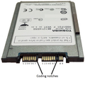
A 1.8-inch micro SATA hard drive with numbered data and power pins on the connector
The micro SATA connector (sometimes called uSATA or μSATA[59]) originated with SATA2.6, and is intended for 1.8-inch hard disk drives. There is also a micro data connector, similar in appearance but slightly thinner than the standard data connector.
Additional pins
Some SATA drives, in particular mechanical ones, come with an extra 4 or more pin interface which isn't uniformly standardized but nevertheless serves similar purpose defined by each drive manufacturer. As IDE drives used those extra pins for setting up Master and Slave drives, on SATA drives, those pins are generally used to select different Power modes for use in USB-SATA bridges or enables additional features like Spread Spectrum Clocking, SATA Speed Limit or Factory Mode for Diagnostics and Recovery, by the use of a jumper.[60][61]
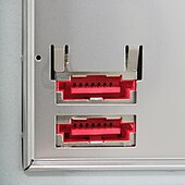
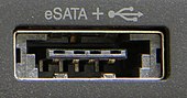
The official eSATA logoSATA (left) and eSATA (right) connectorseSATA ports
Standardized in 2004, eSATA (e standing for external) provides a variant of SATA meant for external connectivity. It uses a more robust connector, longer shielded cables, and stricter (but backward-compatible) electrical standards. The protocol and logical signaling (link/transport layers and above) are identical to internal SATA. The differences are:
Minimum transmit amplitude increased: Range is 500–600mV instead of 400–600mV.
Minimum receive amplitude decreased: Range is 240–600mV instead of 325–600mV.
Maximum cable length increased to 2 meters (6.6ft) from 1 meter (3.3ft).
The eSATA cable and connector is similar to the SATA 1.0a cable and connector, with these exceptions:
The eSATA connector is mechanically different to prevent unshielded internal cables from being used externally. The eSATA connector discards the L-shaped key and changes the position and size of the guides.
The eSATA insertion depth is deeper: 6.6mm instead of 5mm. The contact positions are also changed.
The eSATA cable has an extra shield to reduce EMI to FCC and CE requirements. Internal cables do not need the extra shield to satisfy EMI requirements because they are inside a shielded case.
The eSATA connector uses metal springs for shield contact and mechanical retention.
The eSATA connector has a design-life of 5,000 matings; the ordinary SATA connector is only specified for 50.
Aimed at the consumer market, eSATA enters an external storage market served also by the USB and FireWire interfaces. The SATA interface has certain advantages. Most external hard-disk-drive cases with FireWire or USB interfaces use either PATA or SATA drives and "bridges" to translate between the drives' interfaces and the enclosures' external ports; this bridging incurs some inefficiency. Some single disks can transfer 157MB/s during real use,[17] about four times the maximum transfer rate of USB 2.0 or FireWire 400 (IEEE 1394a) and almost twice as fast as the maximum transfer rate of FireWire 800. The S3200 FireWire 1394b specification reaches around 400MB/s (3.2Gbit/s), and USB 3.0 has a nominal speed of 5Gbit/s. Some low-level drive features, such as S.M.A.R.T., may not operate through some USB[62] or FireWire or USB+FireWire bridges; eSATA does not suffer from these issues provided that the controller manufacturer (and its drivers) presents eSATA drives as ATA devices, rather than as SCSI devices, as has been common with Silicon Image, JMicron, and Nvidia nForce drivers for Windows Vista. In those cases SATA drives do not have low-level features accessible.
The eSATA version of SATA6G operates at 6.0Gbit/s (the term "SATAIII" is avoided by the SATA-IO organization to prevent confusion with SATAII 3.0Gbit/s, which was colloquially referred to as "SATA3G" [bit/s] or "SATA300" [MB/s] since the 1.5Gbit/s SATAI and 1.5Gbit/s SATAII were referred to as both "SATA1.5G" [bit/s] or "SATA150" [MB/s]). Therefore, eSATA connections operate with negligible differences between them.[63] Once an interface can transfer data as fast as a drive can handle them, increasing the interface speed does not improve data transfer.
There are some disadvantages, however, to the eSATA interface:
Devices built before the eSATA interface became popular lack external SATA connectors.
For small form-factor devices (such as external 2.5-inch disks), a PC-hosted USB or FireWire link can usually supply sufficient power to operate the device. However, eSATA connectors cannot supply power, and require a power supply for the external device. The related eSATAp (but mechanically incompatible, sometimes called eSATA/USB) connector adds power to an external SATA connection, so that an additional power supply is not needed.[64]
As of August2017[update] few new computers have dedicated external SATA (eSATA) connectors, with USB3 dominating and USB3 Type C, often with the Thunderbolt alternate mode, starting to replace the earlier USB connectors. Still sometimes present are single ports supporting both USB3 and eSATA.
Desktop computers without a built-in eSATA interface can install an eSATA host bus adapter (HBA); if the motherboard supports SATA, an externally available eSATA connector can be added. Notebook computers with the now rare Cardbus[65] or ExpressCard[66] could add an eSATA HBA. With passive adapters, the maximum cable length is reduced to 1 meter (3.3ft) due to the absence of compliant eSATA signal-levels.
eSATAp stands for powered eSATA. It is also known as Power over eSATA, Power eSATA, eSATA/USB Combo, or eSATA USB Hybrid Port (EUHP). An eSATAp port combines the four pins of the USB2.0 (or earlier) port, the seven pins of the eSATA port, and optionally two 12V power pins.[67] Both SATA traffic and device power are integrated in a single cable, as is the case with USB but not eSATA. The 5V power is provided through two USB pins, while the 12V power may optionally be provided. Typically desktop, but not notebook, computers provide 12V power, so can power devices requiring this voltage, typically 3.5-inch disk and CD/DVD drives, in addition to 5V devices such as 2.5-inch drives.
Both USB and eSATA devices can be used with an eSATAp port, when plugged in with a USB or eSATA cable, respectively. An eSATA device cannot be powered via an eSATAp cable, but a special cable can make both SATA or eSATA and power connectors available from an eSATAp port.
An eSATAp connector can be built into a computer with internal SATA and USB, by fitting a bracket with connections for internal SATA, USB, and power connectors and an externally accessible eSATAp port. Though eSATAp connectors have been built into several devices, manufacturers do not refer to an official standard.
Pre-standard implementations
Prior to the final eSATA 6Gbit/s specification many add-on cards and some motherboards advertised eSATA 6Gbit/s support because they had 6Gbit/s SATA 3.0 controllers for internal-only solutions. Those implementations are non-standard, and eSATA 6Gbit/s requirements were ratified in the July 18, 2011 SATA 3.1 specification.[68] Some products might not be fully eSATA 6Gbit/s compliant.
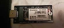
Mini-SATA (abbreviated as mSATA), which is distinct from the micro connector,[59] was announced by the Serial ATA International Organization on September 21, 2009.[69] Applications include netbooks, laptops and other devices that require a solid-state drive in a small footprint.
The physical dimensions of the mSATA connector are identical to those of the PCI Express Mini Card interface,[70] but the interfaces are electrically incompatible; the data signals (TX±/RX± SATA, PETn0 PETp0 PERn0 PERp0 PCI Express) need a connection to the SATA host controller instead of the PCI Express host controller.
The M.2 specification has superseded both mSATA and mini-PCIe.[71]
Slim 2.5-inch SATA devices, 5mm (0.20 inches) in height, use the twenty-pin SFF-8784edge connector to save space. By combining the data signals and power lines into a slim connector that effectively enables direct connection to the device's printed circuit board (PCB) without additional space-consuming connectors, SFF-8784 allows further internal layout compaction for portable devices such as ultrabooks.[72]
Pins 1 to 10 are on the connector's bottom side, while pins 11 to 20 are on the top side.[72]
SATA Express
Two SATA Express connectors (light gray) on a computer motherboard; to the right of them are common SATA connectors (dark gray).
SATA Express, initially standardized in the SATA 3.2 specification,[73] is an interface that supports either SATA or PCI Express storage devices. The host connector is backward compatible with the standard 3.5-inch SATA data connector, allowing up to two legacy SATA devices to connect.[74] At the same time, the host connector provides up to two PCI Express 3.0 lanes as a pure PCI Express connection to the storage device, allowing bandwidths of up to 2GB/s.[32][75]
Instead of the otherwise usual approach of doubling the native speed of the SATA interface, PCI Express was selected for achieving data transfer speeds greater than 6Gbit/s. It was concluded that doubling the native SATA speed would take too much time, too many changes would be required to the SATA standard, and would result in a much greater power consumption when compared to the existing PCI Express bus.[76]
In addition to supporting legacy Advanced Host Controller Interface (AHCI), SATA Express also makes it possible for NVM Express (NVMe) to be used as the logical device interface for connected PCI Express storage devices.[77]
As M.2 form factor, described below, achieved much larger popularity, SATA Express is considered as a failed standard and dedicated ports quickly disappeared from motherboards.
M.2 (NGFF)
Size comparison of mSATA (left) and M.2 (size 2242, right) SSDsAn M.2 (2242) solid-state-drive (SSD) connected into USB 3.0 adapter and connected to computer
M.2, formerly known as the Next Generation Form Factor (NGFF), is a specification for computer expansion cards and associated connectors. It replaces the mSATA standard, which uses the PCI Express Mini Card physical layout. Having a smaller and more flexible physical specification, together with more advanced features, the M.2 is more suitable for solid-state storage applications in general, especially when used in small devices such as ultrabooks or tablets.[78]
The M.2 standard is designed as a revision and improvement to the mSATA standard, so that larger printed circuit boards (PCBs) can be manufactured. While mSATA took advantage of the existing PCI Express Mini Card form factor and connector, M.2 has been designed to maximize usage of the card space, while minimizing the footprint.[78][79][80]
Supported host controller interfaces and internally provided ports are a superset to those defined by the SATA Express interface. Essentially, the M.2 standard is a small form factor implementation of the SATA Express interface, with the addition of an internal USB3.0 port.[78]
U.2 (SFF-8639)
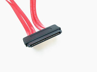
U.2, formerly known as SFF-8639. Like M.2, it carries a PCI Express electrical signal, however U.2 uses a PCIe 3.0 ×4 link providing a higher bandwidth of 32Gbit/s in each direction. In order to provide maximum backward compatibility the U.2 connector also supports SATA and multi-path SAS.[81]
SATA topology: host (H), multiplier (M), and device (D)
SATA uses a point-to-point architecture. The physical connection between a controller and a storage device is not shared among other controllers and storage devices. SATA defines multipliers, which allows a single SATA controller port to drive up to fifteen storage devices. The multiplier performs the function of a hub; the controller and each storage device is connected to the hub.[82] This is conceptually similar to SAS expanders.
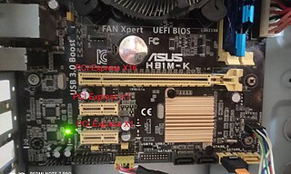
Modern[update] PC systems have SATA controllers built into the motherboard, typically featuring two to eight ports. Additional ports can be installed through add-in SATA host adapters (available in variety of bus-interfaces: USB, PCI, PCIe).
Backward and forward compatibility
SATA and PATA
PATA hard disk with SATA converter attached
At the hardware interface level, SATA and PATA (Parallel AT Attachment) devices are completely incompatible: they cannot be interconnected without an adapter.
At the application level, SATA devices can be specified to look and act like PATA devices.[83]
Many motherboards offer a "Legacy Mode" option, which makes SATA drives appear to the OS like PATA drives on a standard controller. This Legacy Mode eases OS installation by not requiring that a specific driver be loaded during setup, but sacrifices support for some (vendor specific) features of SATA. Legacy Mode often if not always disables some of the boards' PATA or SATA ports, since the standard PATA controller interface supports only four drives. (Often, which ports are disabled is configurable.)
The common heritage of the ATA command set has enabled the proliferation of low-cost PATA to SATA bridge chips. Bridge chips were widely used on PATA drives (before the completion of native SATA drives) as well in standalone converters. When attached to a PATA drive, a device-side converter allows the PATA drive to function as a SATA drive. Host-side converters allow a motherboard PATA port to connect to a SATA drive.
The market has produced powered enclosures for both PATA and SATA drives that interface to the PC through USB, Firewire or eSATA, with the restrictions noted above. PCI cards with a SATA connector exist that allow SATA drives to connect to legacy systems without SATA connectors.
SATA 1.5Gbit/s and SATA 3Gbit/s
The designers of SATA standard as an overall goal aimed for backward and forward compatibility with future revisions of the SATA standard. To prevent interoperability problems that could occur when next generation SATA drives are installed on motherboards with standard legacy SATA 1.5Gbit/s host controllers, many manufacturers have made it easy to switch those newer drives to the previous standard's mode. Examples of such provisions include:
Seagate/Maxtor has added a user-accessible jumper-switch, known as the "force 150", to enable the drive switch between forced 1.5Gbit/s and 1.5/3Gbit/s negotiated operation.
Western Digital uses a jumper setting called OPT1 enabled to force 1.5Gbit/s data transfer speed (OPT1 is enabled by putting the jumper on pins 5 and 6).[84]
Samsung drives can be forced to 1.5Gbit/s mode using software that may be downloaded from the manufacturer's website. Configuring some Samsung drives in this manner requires the temporary use of a SATA-2 (SATA 3.0Gbit/s) controller while programming the drive.
The "force 150" switch (or equivalent) is also useful for attaching SATA 3Gbit/s hard drives to SATA controllers on PCI cards, since many of these controllers (such as the Silicon Image chips) run at 3Gbit/s, even though the PCI bus cannot reach 1.5Gbit/s speeds. This can cause data corruption in operating systems that do not specifically test for this condition and limit the disk transfer speed.[citation needed]
SATA 3Gbit/s and SATA 6Gbit/s
This section needs expansion. You can help by adding to it. (October 2011)
SATA 3Gbit/s and SATA 6Gbit/s are compatible with each other. Most devices that are only SATA 3Gbit/s can connect with devices that are SATA 6Gbit/s, and vice versa, though SATA 3Gbit/s devices connect with SATA 6Gbit/s devices only at the slower 3Gbit/s speed.
SATA 1.5Gbit/s and SATA 6Gbit/s
This section needs expansion. You can help by adding to it. (July 2013)
SATA 1.5Gbit/s and SATA 6Gbit/s are compatible with each other. Most devices that are only SATA 1.5Gbit/s can connect with devices that are SATA 6Gbit/s, and vice versa, though SATA 1.5Gbit/s devices only connect with SATA 6Gbit/s devices at the slower 1.5Gbit/s speed.
Comparison to other interfaces
SATA and SCSI
Parallel SCSI uses a more complex bus than SATA, usually resulting in higher manufacturing costs. SCSI buses also allow connection of several drives on one shared channel, whereas SATA allows one drive per channel, unless using a port multiplier. Serial Attached SCSI uses the same physical interconnects as SATA, and most SAS HBAs also support 3 and 6Gbit/s SATA devices (an HBA requires support for Serial ATA Tunneling Protocol).
SATA 3Gbit/s theoretically offers a maximum bandwidth of 300MB/s per device, which is only slightly lower than the rated speed for SCSI Ultra 320 with a maximum of 320MB/s total for all devices on a bus.[85] SCSI drives provide greater sustained throughput than multiple SATA drives connected via a simple (i.e., command-based) port multiplier because of disconnect-reconnect and aggregating performance.[86] In general, SATA devices link compatibly to SAS enclosures and adapters, whereas SCSI devices cannot be directly connected to a SATA bus.
SCSI, SAS[citation needed], and fibre-channel (FC) drives are more expensive than SATA, so they are used in servers and disk arrays where the better performance justifies the additional cost. Inexpensive ATA and SATA drives evolved in the home-computer market, hence there is a view that they are less reliable. As those two worlds overlapped, the subject of reliability became somewhat controversial. Note that, in general, the failure rate of a disk drive is related to the quality of its heads, platters and supporting manufacturing processes, not to its interface.
Use of serial ATA in the business market increased from 22% in 2006 to 28% in 2008.[9]
SCSI-3 devices with SCA-2 connectors are designed for hot swapping. Many server and RAID systems provide hardware support for transparent hot swapping. The designers of the SCSI standard prior to SCA-2 connectors did not target hot swapping, but in practice, most RAID implementations support hot swapping of hard disks.
↑ "AT" is derived from the IBM Personal Computer/AT. IBM did not specify a meaning for AT and neither did the Serial ATA International Organization in the specification document. The standard is marketed as Serial ATA, but SATA is the most common name.
↑ Disk-based memory (hard drives), solid state disk devices such as USB drives, DVD-based storage, bit rates, bus speeds, and network speeds, are specified using decimal meanings for k (10001), M (10002), G (10003), etc.
Parallel ATA (PATA), originally AT Attachment, also known as Integrated Drive Electronics (IDE), is a standard interface designed for IBM PC-compatible computers. It was first developed by Western Digital and Compaq in 1986 for compatible hard drives and CD or DVD drives. The connection is used for storage devices such as hard disk drives, floppy disk drives, optical disc drives, and tape drives in computers.
Industry Standard Architecture (ISA) is the 16-bit internal bus of IBM PC/AT and similar computers based on the Intel 80286 and its immediate successors during the 1980s. The bus was (largely) backward compatible with the 8-bit bus of the 8088-based IBM PC, including the IBM PC/XT as well as IBM PC compatibles.
Small Computer System Interface is a set of standards for physically connecting and transferring data between computers and peripheral devices, best known for its use with storage devices such as hard disk drives. SCSI was introduced in the 1980s and has seen widespread use on servers and high-end workstations, with new SCSI standards being published as recently as SAS-4 in 2017.
Universal Serial Bus (USB) is an industry standard that allows data exchange and delivery of power between many various types of electronics. It specifies its architecture, in particular its physical interface, and communication protocols for data transfer and power delivery to and from hosts, such as personal computers, to and from peripheral devices, e.g. displays, keyboards, and mass storage devices, and to and from intermediate hubs, which multiply the number of a host's ports.
PCI Express, officially abbreviated as PCIe or PCI-e, is a high-speed serial computer expansion bus standard, designed to replace the older PCI, PCI-X and AGP bus standards. It is the common motherboard interface for personal computers' graphics cards, sound cards, hard disk drive host adapters, SSDs, Wi-Fi and Ethernet hardware connections. PCIe has numerous improvements over the older standards, including higher maximum system bus throughput, lower I/O pin count and smaller physical footprint, better performance scaling for bus devices, a more detailed error detection and reporting mechanism, and native hot-swap functionality. More recent revisions of the PCIe standard provide hardware support for I/O virtualization.
CompactFlash (CF) is a flash memory mass storage device used mainly in portable electronic devices. The format was specified and the devices were first manufactured by SanDisk in 1994.
In computer hardware, a host controller, host adapter, or host bus adapter (HBA), connects a computer system bus, which acts as the host system, to other network and storage devices. The terms are primarily used to refer to devices for connecting SCSI, SAS, NVMe, Fibre Channel and SATA devices. Devices for connecting to FireWire, USB and other devices may also be called host controllers or host adapters.
The Advanced Host Controller Interface (AHCI) is a technical standard defined by Intel that specifies the register-level interface of Serial ATA (SATA) host controllers in a non-implementation-specific manner in its motherboard chipsets.
In computing, Serial Attached SCSI (SAS) is a point-to-point serial protocol that moves data to and from computer-storage devices such as hard disk drives and tape drives. SAS replaces the older Parallel SCSI bus technology that first appeared in the mid-1980s. SAS, like its predecessor, uses the standard SCSI command set. SAS offers optional compatibility with Serial ATA (SATA), versions 2 and later. This allows the connection of SATA drives to most SAS backplanes or controllers. The reverse, connecting SAS drives to SATA backplanes, is not possible.
The Western Digital Raptor is a discontinued series of high performance hard disk drives produced by Western Digital first marketed in 2003. The drive occupied a niche in the enthusiast, workstation and small-server market. Traditionally, the majority of servers used hard drives featuring a SCSI interface because of their advantages in both performance and reliability over consumer-level ATA drives.
The i-RAM was a PCI card-mounted, battery-backed RAM disk that behaved and was marketed as a solid-state storage device. It was produced by Gigabyte and released in June 2005, at a time when genuine solid-state storage solutions were generally still less affordable than an i-RAM product with superficially similar capabilities. Since the i-RAM used DRAM, which is volatile memory, and it had a lithium-ion battery on board, though it only needed to fall back on battery backup power when the computer it was installed in was unplugged or completely turned off, as the card was able to draw power sufficient for RAM refresh from the PCI bus, which still has standby power present even when an ATX machine is shut down. The contents of the DRAM could however only be preserved for a limited amount of time after the power supply was fully interrupted.
A solid-state drive (SSD) is a solid-state storage device. It provides persistent data storage using no moving parts.
I/O Controller Hub (ICH) is a family of Intel southbridge microchips used to manage data communications between a CPU and a motherboard, specifically Intel chipsets based on the Intel Hub Architecture. It is designed to be paired with a second support chip known as a northbridge. As with any other southbridge, the ICH is used to connect and control peripheral devices.
Universal Serial Bus 3.0, marketed as SuperSpeed USB, is the third major version of the Universal Serial Bus (USB) standard for interfacing computers and electronic devices. It was released in November 2008. The USB 3.0 specification defined a new architecture and protocol, named SuperSpeed, which included a new lane for a new signal coding scheme providing full-duplex data transfers that physically required five additional wires and pins, while preserving the USB 2.0 architecture and protocols and therefore keeping the original four pins and wires for the USB 2.0 backward-compatibility, resulting in nine wires in total and nine or ten pins at connector interfaces. The new transfer rate, marketed as SuperSpeed USB (SS), can transfer signals at up to 5 Gbit/s with nominal data rate of 500 MB/s after encoding overhead, which is about 10 times faster than High-Speed. USB 3.0 Type-A and B connectors are usually blue, to distinguish them from USB 2.0 connectors, as recommended by the specification. and by the initials SS.
Spin-up refers to the process of a hard disk drive or optical disc drive accelerating its platters or inserted optical disc from a stopped state to an operational speed. The required operational speed depends on the design of the disk drive. Typical speeds of hard disks have been 2400, 3600, 4200, 5400, 7200, 10000 and 15000 revolutions per minute (RPM). Achieving such speeds can require a significant portion of the available power budget of a computer system, and so application of power to the disks must be carefully controlled. Operational speed of optical disc drives may vary depending on type of disc and mode of operation.
A Serial ATA port multiplier is a device that allows multiple SATA devices to be connected to a single SATA host port. Many common controllers do not support this feature, as it is not a requirement for a SATA controller.
In computing, eSATAp is a combination connection for external storage devices. An eSATA or USB device can be plugged into an eSATAp port. The socket has keyed cutouts for both types of device to ensure that a connector can only be plugged in the right way.
Hard disk drives are accessed over one of a number of bus types, including parallel ATA, Serial ATA (SATA), SCSI, Serial Attached SCSI (SAS), and Fibre Channel. Bridge circuitry is sometimes used to connect hard disk drives to buses with which they cannot communicate natively, such as IEEE 1394, USB, SCSI, NVMe and Thunderbolt.
M.2, pronounced m dot two and formerly known as the Next Generation Form Factor (NGFF), is a specification for internally mounted computer expansion cards and associated connectors. M.2 replaces the Mini-SATA (mSATA) standard, which uses the PCI Express Mini Card physical card layout and connectors. Employing a more flexible physical specification, M.2 allows different module widths and lengths, which, paired with the availability of more advanced interfacing features, makes M.2 more suitable than mSATA in general for solid-state storage applications, particularly in smaller devices such as ultrabooks and tablets.
SATA Express is a computer bus interface that supports both Serial ATA (SATA) and PCI Express (PCIe) storage devices, initially standardized in the SATA 3.2 specification. The SATA Express connector used on the host side is backward compatible with the standard SATA data connector, while it also provides two PCI Express lanes as a pure PCI Express connection to the storage device.
↑ Jim Handy; Jon Tanguy; Jaren May; David Akerson; Eden Kim; Tom Coughlin (September 20, 2014). "SNIA Webcast: All About M.2 SSDs"(PDF). SNIA. Retrieved July 15, 2015.
This page is based on this Wikipedia article Text is available under the CC BY-SA 4.0 license; additional terms may apply. Images, videos and audio are available under their respective licenses.