This article's lead sectionmay be too short to adequately summarize the key points. Please consider expanding the lead to provide an accessible overview of all important aspects of the article.(November 2023)
Water turbines were developed in the 19th century and were widely used for industrial power prior to electrical grids. Now, they are mostly used for electric power generation. Water turbines are mostly found in dams to generate electric power from water potential energy.
History
The construction of a Ganz water Turbo Generator in Budapest in 1886
Water wheels have been used for hundreds of years for industrial power. Their main shortcoming is size, which limits the flow rate and head that can be harnessed. The migration from water wheels to modern turbines took about one hundred years. Development occurred during the Industrial Revolution, using scientific principles and methods. They also made extensive use of new materials and manufacturing methods developed at the time.
Swirl
The word turbine was introduced by the French engineer Claude Burdin in the early 19th century and is derived from the Greek word "τύρβη" for "whirling" or a "vortex". The main difference between early water turbines and water wheels is a swirl component of the water which passes energy to a spinning rotor. This additional component of motion allowed the turbine to be smaller than a water wheel of the same power. They could process more water by spinning faster and could harness much greater heads. (Later, impulse turbines were developed which didn't use swirl.)
Timeline
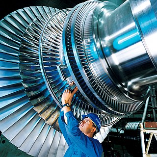
Roman turbine mill at Chemtou, Tunisia. The tangential water inflow of the mill race made the submerged horizontal wheel in the shaft turn like a true turbine.A Francis turbine runner, rated at nearly one million hp (750 MW), being installed at the Grand Coulee Dam, United States.A propeller-type runner rated 28,000 hp (21 MW)
The earliest known water turbines date to the Roman Empire. Two helix-turbine mill sites of almost identical design were found at Chemtou and Testour, modern-day Tunisia, dating to the late 3rd or early 4th century AD. The horizontal water wheel with angled blades was installed at the bottom of a water-filled, circular shaft. The water from the mill race entered the pit tangentially, creating a swirling water column which made the fully submerged wheel act like a true turbine.[1]
Fausto Veranzio in his book Machinae Novae (1595) described a vertical axis mill with a rotor similar to that of a Francis turbine.[2]
Johann Segner developed a reactive water turbine (Segner wheel) in the mid-18th century in Kingdom of Hungary. It had a horizontal axis and was a precursor to modern water turbines. It is a very simple machine that is still produced today for use in small hydro sites. Segner worked with Euler on some of the early mathematical theories of turbine design. In the 18th century, a Dr. Robert Barker invented a similar reaction hydraulic turbine that became popular as a lecture-hall demonstration.[3] The only known surviving example of this type of engine used in power production, dating from 1851, is found at Hacienda Buena Vista in Ponce, Puerto Rico.[4]
In 1826, Benoît Fourneyron developed an outward-flow turbine. This was an efficient machine (~80%) that sent water through a runner with blades curved in one dimension. The stationary outlet also had curved guides.
In 1844, Uriah A. Boyden developed an outward flow turbine that improved on the performance of the Fourneyron turbine. Its runner shape was similar to that of a Francis turbine.
In 1849, James B. Francis improved the inward flow reaction turbine to over 90% efficiency. He also conducted sophisticated tests and developed engineering methods for water turbine design. The Francis turbine, named for him, is the first modern water turbine. It is still the most widely used water turbine in the world today. The Francis turbine is also called a radial flow turbine, since water flows from the outer circumference towards the centre of runner.
Inward flow water turbines have a better mechanical arrangement and all modern reaction water turbines are of this design. As the water swirls inward, it accelerates, and transfers energy to the runner. Water pressure decreases to atmospheric, or in some cases subatmospheric, as the water passes through the turbine blades and loses energy.
In 1876, John B. McCormick, building on Francis's designs, demonstrated the first modern mixed-flow turbine with the development of the Hercules turbine, initially manufactured by the Holyoke Machine Company and subsequently improved upon by engineers in Germany and the United States.[5] The design effectively combined the inward flow principles of the Francis design with the downward discharge of the Jonval turbine, with flow inward at the inlet, axial through the wheel's body, and slightly outward at the outlet. Initially performing optimally at 90% efficiency at lower speeds, this design would see many improvements in the subsequent decades in derivatives under names like "Victor", "Risdon", "Samson" and "New American," ushering in a new era of American turbine engineering.[6][7]
Water turbines, particularly in the Americas, would largely become standardized with the establishment of the Holyoke Testing Flume, described as the first modern hydraulic laboratory in the United States by Robert E. Horton and Clemens Herschel, the latter of which would serve as its chief engineer for a time.[8][9] Initially created in 1872 by James B. Emerson from the testing flumes of Lowell, after 1880 the Holyoke, Massachusetts hydraulic laboratory was standardized by Herschel, who used it to develop the Venturi meter, the first accurate means of measuring large flows, to properly measure water power efficiency by different turbine models.[10][11][12] While skepticism of certain weir calculations were held by European hydrologists, the facility allowed for standard efficiency testing among major manufacturers through 1932, by which time more modern facilities and methods had proliferated.[13][14]:100
Around 1890, the modern fluid bearing was invented, now universally used to support heavy water turbine spindles. As of 2002, fluid bearings appear to have a mean time between failures of more than 1300 years.
Around 1913, Viktor Kaplan created the Kaplan turbine, a propeller-type machine. It was an evolution of the Francis turbine and revolutionized the ability to develop low-head hydro sites.
Figure from Pelton's original patent (October 1880)
All common water machines until the late 19th century (including water wheels) were basically reaction machines; water pressure head acted on the machine and produced work. A reaction turbine needs to fully contain the water during energy transfer.
In 1866, California millwright Samuel Knight invented a machine that took the impulse system to a new level.[15][16] Inspired by the high pressure jet systems used in hydraulic mining in the gold fields, Knight developed a bucketed wheel which captured the energy of a free jet, which had converted a high head (hundreds of vertical feet in a pipe or penstock) of water to kinetic energy. This is called an impulse or tangential turbine. The water's velocity, roughly twice the velocity of the bucket periphery, does a U-turn in the bucket and drops out of the runner at low velocity.
In 1879, Lester Pelton, experimenting with a Knight Wheel, developed a Pelton wheel (double bucket design), which exhausted the water to the side, eliminating some energy loss of the Knight wheel which exhausted some water back against the center of the wheel. In about 1895, William Doble improved on Pelton's half-cylindrical bucket form with an elliptical bucket that included a cut in it to allow the jet a cleaner bucket entry. This is the modern form of the Pelton turbine which today achieves up to 92% efficiency. Pelton had been quite an effective promoter of his design and although Doble took over the Pelton company he did not change the name to Doble because it had brand name recognition.
Flowing water is directed on to the blades of a turbine runner, creating a force on the blades. Since the runner is spinning, the force acts through a distance (force acting through a distance is the definition of work). In this way, energy is transferred from the water flow to the turbine.
Water turbines are divided into two groups: reaction turbines and impulse turbines.
The precise shape of water turbine blades is a function of the supply pressure of water, and the type of impeller selected.
Reaction turbines
Reaction turbines are acted on by water, which changes pressure as it moves through the turbine and gives up its energy. They must be encased to contain the water pressure (or suction), or they must be fully submerged in the water flow.
Newton's third law describes the transfer of energy for reaction turbines.
Most water turbines in use are reaction turbines and are used in low (<30m or 100ft) and medium (30–300m or 100–1,000ft) head applications. In reaction turbine pressure drop occurs in both fixed and moving blades. It is largely used in dam and large power plants
Impulse turbines
Impulse turbines change the velocity of a water jet. The jet pushes on the turbine's curved blades which changes the direction of the flow. The resulting change in momentum (impulse) causes a force on the turbine blades. Since the turbine is spinning, the force acts through a distance (work) and the diverted water flow is left with diminished energy. An impulse turbine is one in which the pressure of the fluid flowing over the rotor blades is constant and all the work output is due to the change in kinetic energy of the fluid.
Prior to hitting the turbine blades, the water's pressure (potential energy) is converted to kinetic energy by a nozzle and focused on the turbine. No pressure change occurs at the turbine blades, and the turbine doesn't require a housing for operation.
Newton's second law describes the transfer of energy for impulse turbines.
Impulse turbines are often used in very high (>300m/1000ft) head applications.
head (m). For still water, this is the difference in height between the inlet and outlet surfaces. Moving water has an additional component added to account for the kinetic energy of the flow. The total head equals the pressure head plus velocity head.
= flow rate (m3/s)
Pumped-storage hydroelectricity
Some water turbines are designed for pumped-storage hydroelectricity. They can reverse flow and operate as a pump[1] to fill a high reservoir during off-peak electrical hours, and then revert to a water turbine for power generation during peak electrical demand. This type of turbine is usually a Deriaz or Francis turbine in design.
This type of system is used in El Hierro, one of the Canary Islands: "When wind production exceeds demand, excess energy will pump water from a lower reservoir at the bottom of a volcanic cone to an upper reservoir at the top of the volcano 700 meters above sea level. The lower reservoir stores 150,000 cubic meters of water. The stored water acts as a battery. The maximum storage capacity is 270 MWh. When demand rises and there is not enough wind power, the water will be released to four hydroelectric turbines with a total capacity of 11 MW."[17][18]
Various types of water turbine runners. From left to right: Pelton wheel, two types of Francis turbine and Kaplan turbine.A decommissioned Francis turbine runner on display at the Raccoon Mountain Pumped-Storage Plant
Turbine selection is based on the available water head, and less so on the available flow rate. In general, impulse turbines are used for high head sites, and reaction turbines are used for low head sites. Kaplan turbines with adjustable blade pitch are well-adapted to wide ranges of flow or head conditions, since their peak efficiency can be achieved over a wide range of flows.
Small turbines (mostly under 10 MW) may have horizontal shafts, and even fairly large bulb-type turbines up to 100 MW or so may be horizontal. Very large Francis and Kaplan machines usually have vertical shafts because this makes best use of the available head, and makes installation of a generator more economical. Pelton wheels may be either vertical or horizontal shaft machines because the size of the machine is so much less than the available head. Some impulse turbines use multiple jets per runner to balance shaft thrust. This also allows for the use of a smaller turbine runner, which can decrease costs and mechanical losses.
The specific speed of a turbine characterizes the turbine's shape in a way that is not related to its size. This allows a new turbine design to be scaled from an existing design of known performance. The specific speed is also the main criteria for matching a specific hydro site with the correct turbine type. The specific speed is the speed with which the turbine turns for a particular discharge Q, with unit head and thereby is able to produce unit power.
Affinity laws
Affinity laws allow the output of a turbine to be predicted based on model tests. A miniature replica of a proposed design, about one foot (0.3 m) in diameter, can be tested and the laboratory measurements applied to the final application with high confidence. Affinity laws are derived by requiring similitude between the test model and the application.
Flow through the turbine is controlled either by a large valve or by wicket gates arranged around the outside of the turbine runner. Differential head and flow can be plotted for a number of different values of gate opening, producing a hill diagram used to show the efficiency of the turbine at varying conditions.
Runaway speed
The runaway speed of a water turbine is its speed at full flow, and no shaft load. The turbine will be designed to survive the mechanical forces of this speed. The manufacturer will supply the runaway speed rating.
Control systems
Operation of a flyball governor to control speeds of a water turbine
Different designs of governors have been used since the mid-18th century to control the speeds of the water turbines. A variety of flyball systems, or first-generation governors, were used during the first 100 years of water turbine speed controls. In early flyball systems, the flyball component countered by a spring acted directly to the valve of the turbine or the wicket gate to control the amount of water that enters the turbines. Newer systems with mechanical governors started around 1880. An early mechanical governor is a servomechanism that comprises a series of gears that use the turbine's speed to drive the flyball and turbine's power to drive the control mechanism. The mechanical governors were continued to be enhanced in power amplification through the use of gears and the dynamic behavior. By 1930, the mechanical governors had many parameters that could be set on the feedback system for precise controls. In the later part of the twentieth century, electronic governors and digital systems started to replace the mechanical governors. In the electronic governors, also known as second-generation governors, the flyball was replaced by rotational speed sensor but the controls were still done through analog systems. In the modern systems, also known as third-generation governors, the controls are performed digitally by algorithms that are programmed to the computer of the governor.[20]
Wicket gate
Wicket gates (yellow) surrounding a Francis type turbine. Varying their angle manages water flow, thereby regulating turbine speed and energy produced by it.
A wicket gate, or guide vane, is a ring of gates (or vanes) surrounding a water turbine which control the flow of water entering it; varying the aperture between them manages the rate of the turbine's spin, and thereby the amount of electricity generated.[21]
Turbine blade materials
Given that the turbine blades in a water turbine are constantly exposed to water and dynamic forces, they need to have high corrosion resistance and strength. The most common material used in overlays on carbon steel runners in water turbines are austenitic steel alloys that have 17% to 20% chromium to increase stability of the film which improves aqueous corrosion resistance. The chromium content in these steel alloys exceed the minimum of 12% chromium required to exhibit some atmospheric corrosion resistance. Having a higher chromium concentration in the steel alloys allows for a much longer lifespan of the turbine blades. Currently, the blades are made of martensitic stainless steels which have high strength compared to austenitic stainless steels by a factor of 2.[22] Along with corrosion resistance and strength, weld-ability and density are important criteria for turbine blade material selection. Greater weld-ability allows for easier and high quality repairs. Low density allows higher efficiency through easier rotation. The most common material used in Kaplan Turbine blades are stainless steel alloys (SS). The martensitic stainless steel alloys have high strength that allow thinner sections than standard carbon steel; reduced mass enhances the hydrodynamic flow conditions and efficiency of the water turbine.[22] The SS(13Cr-4Ni) has been shown to have improved erosion resistance at all angles of attack through the process of laser peening.[23] It is important to minimize erosion in order to maintain high efficiencies because erosion negatively impacts the hydraulic profile of the blades which reduces the relative ease of rotation.[24]
Turbines are designed to run for decades with very little maintenance of the main elements; overhaul intervals are on the order of several years. Maintenance of the runners and parts exposed to water include removal, inspection, and repair of worn parts.
Normal wear and tear includes pitting corrosion from cavitation, fatigue cracking, and abrasion from suspended solids in the water. Steel elements are repaired by welding, usually with stainless steel rods. Damaged areas are cut or ground out, then welded back up to their original or an improved profile. Old turbine runners may have a significant amount of stainless steel added this way by the end of their lifetime. Elaborate welding procedures may be used to achieve the highest quality repairs.[25]
Other elements requiring inspection and repair during overhauls include bearings, packing box and shaft sleeves, servomotors, cooling systems for the bearings and generator coils, seal rings, wicket gate linkage elements and all surfaces.[26]
Water turbines are generally considered a clean power producer, as the turbine causes essentially no change to the water. They use a renewable energy source and are designed to operate for decades. They produce significant amounts of the world's electrical supply.
Negative consequences of water turbines are mostly associated with the dams normally required for their operation. Dams alter the natural ecology of rivers, potentially killing fish, stopping migrations, and disrupting livelihoods. Dams also cause less obvious, but potentially serious, consequences, including increased evaporation of water (especially in arid regions), buildup of silt behind the dam,[clarify] and changes to water temperature and flow patterns. In the United States, it is now illegal to block the migration of fish, so fish ladders for species such as salmon and white sturgeon must be provided by dam builders.[citation needed]
Hydropower, also known as water power, is the use of falling or fast-running water to produce electricity or to power machines. This is achieved by converting the gravitational potential or kinetic energy of a water source to produce power. Hydropower is a method of sustainable energy production. Hydropower is now used principally for hydroelectric power generation, and is also applied as one half of an energy storage system known as pumped-storage hydroelectricity.
The Pelton wheel or Pelton Turbine is an impulse-type water turbine invented by American inventor Lester Allan Pelton in the 1870s. The Pelton wheel extracts energy from the impulse of moving water, as opposed to water's dead weight like the traditional overshot water wheel. Many earlier variations of impulse turbines existed, but they were less efficient than Pelton's design. Water leaving those wheels typically still had high speed, carrying away much of the dynamic energy brought to the wheels. Pelton's paddle geometry was designed so that when the rim ran at half the speed of the water jet, the water left the wheel with very little speed; thus his design extracted almost all of the water's impulse energy—which made for a very efficient turbine.
A steam turbine is a machine that extracts thermal energy from pressurized steam and uses it to do mechanical work on a rotating output shaft. Its modern manifestation was invented by Charles Parsons in 1884. Fabrication of a modern steam turbine involves advanced metalwork to form high-grade steel alloys into precision parts using technologies that first became available in the 20th century; continued advances in durability and efficiency of steam turbines remains central to the energy economics of the 21st century.
A turbine is a rotary mechanical device that extracts energy from a fluid flow and converts it into useful work. The work produced can be used for generating electrical power when combined with a generator. A turbine is a turbomachine with at least one moving part called a rotor assembly, which is a shaft or drum with blades attached. Moving fluid acts on the blades so that they move and impart rotational energy to the rotor. Early turbine examples are windmills and waterwheels.
A water wheel is a machine for converting the energy of flowing or falling water into useful forms of power, often in a watermill. A water wheel consists of a wheel, with a number of blades or buckets arranged on the outside rim forming the driving car. Water wheels were still in commercial use well into the 20th century, but they are no longer in common use today. Uses included milling flour in gristmills, grinding wood into pulp for papermaking, hammering wrought iron, machining, ore crushing and pounding fibre for use in the manufacture of cloth.
A cross-flow turbine, Bánki-Michell turbine, or Ossberger turbine is a water turbine developed by the Australian Anthony Michell, the Hungarian Donát Bánki and the German Fritz Ossberger. Michell obtained patents for his turbine design in 1903, and the manufacturing company Weymouth made it for many years. Ossberger's first patent was granted in 1933, and he manufactured this turbine as a standard product. Today, the company founded by Ossberger which bears his name is the leading manufacturer of this type of turbine.
The Francis turbine is a type of water turbine. It is an inward-flow reaction turbine that combines radial and axial flow concepts. Francis turbines are the most common water turbine in use today, and can achieve over 95% efficiency.
The Kaplan turbine is a propeller-type water turbine which has adjustable blades. It was developed in 1913 by Austrian professor Viktor Kaplan, who combined automatically adjusted propeller blades with automatically adjusted wicket gates to achieve efficiency over a wide range of flow and water level.
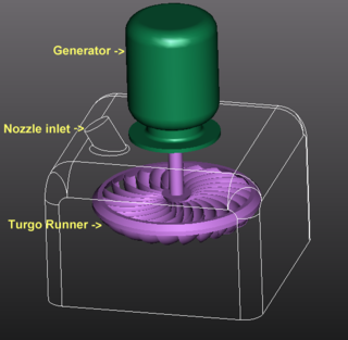
The Turgo turbine is an impulse water turbine designed for medium head applications. Operational Turgo turbines achieve efficiencies of about 87%. In factory and lab tests Turgo turbines perform with efficiencies of up to 90%. It works with net heads between 15 and 300 m.
Lester Allan Pelton was an American inventor who contributed significantly to the development of hydroelectricity and hydropower in the American Old West as well as world-wide. In the late 1870s, he invented the Pelton water wheel, at that time the most efficient design of the impulse water turbine. Recognized as one of the fathers of hydroelectric power, he was awarded the Elliott Cresson Medal during his lifetime and is an inductee of the National Inventors Hall of Fame.
Turbomachinery, in mechanical engineering, describes machines that transfer energy between a rotor and a fluid, including both turbines and compressors. While a turbine transfers energy from a fluid to a rotor, a compressor transfers energy from a rotor to a fluid. It is an important application of fluid mechanics.
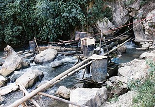
Micro hydro is a type of hydroelectric power that typically produces from 5 kW to 100 kW of electricity using the natural flow of water. Installations below 5 kW are called pico hydro. These installations can provide power to an isolated home or small community, or are sometimes connected to electric power networks, particularly where net metering is offered. There are many of these installations around the world, particularly in developing nations as they can provide an economical source of energy without the purchase of fuel. Micro hydro systems complement solar PV power systems because in many areas water flow, and thus available hydro power, is highest in the winter when solar energy is at a minimum. Micro hydro is frequently accomplished with a pelton wheel for high head, low flow water supply. The installation is often just a small dammed pool, at the top of a waterfall, with several hundred feet of pipe leading to a small generator housing. In low head sites, generally water wheels and Archimedes' screws are used.
Specific speedNs, is used to characterize turbomachinery speed. Common commercial and industrial practices use dimensioned versions which are of equal utility. Specific speed is most commonly used in pump applications to define the suction specific speed —a quasi non-dimensional number that categorizes pump impellers as to their type and proportions. In Imperial units it is defined as the speed in revolutions per minute at which a geometrically similar impeller would operate if it were of such a size as to deliver one gallon per minute against one foot of hydraulic head. In metric units flow may be in l/s or m3/s and head in m, and care must be taken to state the units used.
The Gorlov helical turbine (GHT) is a water turbine evolved from the Darrieus turbine design by altering it to have helical blades/foils. Water turbines take kinetic energy and translate it into electricity. It was patented in a series of patents from September 19, 1995 to July 3, 2001 and won 2001 ASME Thomas A. Edison. GHT was invented by Alexander M. Gorlov, professor of Northeastern University.
Low-head hydropower refers to the development of hydroelectric power where the head is typically less than 20 metres, although precise definitions vary. Head is the vertical height measured between the hydro intake water level and the water level at the point of discharge. Using only a low head drop in a river or tidal flows to create electricity may provide a renewable energy source that will have a minimal impact on the environment. Since the generated power is a function of the head these systems are typically classed as small-scale hydropower, which have an installed capacity of less than 5MW.
Francis turbine converts energy at high pressure heads which are not easily available and hence a turbine was required to convert the energy at low pressure heads, given that the quantity of water was large enough. It was easy to convert high pressure heads to power easily but difficult to do so for low pressure heads. Therefore, an evolution took place that converted the Francis turbine to Kaplan turbine, which generated power at even low pressure heads efficiently.
A pump as turbine (PAT), also known as a pump in reverse, is an unconventional type of reaction water turbine, which behaves in a similar manner to that of a Francis turbine. The function of a PAT is comparable to that of any turbine, to convert kinetic and pressure energy of the fluid into mechanical energy of the runner. They are commonly commercialized as composite pump and motor/generator units, coupled by a fixed shaft to an asynchronous induction type motor unit.
The water wall turbine is a water turbine designed to utilize hydrostatic pressure differences for low head hydropower generation. It supports bidirectional inflow operation using radial blades that rotate around a horizontal axis. The water wall turbine is suitable for energy extraction from tidal and freshwater currents. For tidal power installations, the turbine operates in both directions as the tide ebbs and flows.
Radial means that the fluid is flowing in radial direction that is either from inward to outward or from outward to inward, with respect to the runner shaft axis. If the fluid is flowing from inward to outward then it is called outflow radial turbine.
In this turbine, the working fluid enters around the axis of the wheel and then flows outwards.
The guide vane mechanism is typically surrounded by the runner/turbine.
In this turbine, the inner diameter of the runner is the inlet and outer diameter is an outlet.
The Holyoke Testing Flume was a hydraulic testing laboratory and apparatus in Holyoke, Massachusetts, operated by the Holyoke Water Power Company from 1870 to 1932, and used to test the performance of water turbine designs, completing 3,176 tests of efficiency in that time. It was described by Robert E. Horton in court testimony as the only facility of its kind in the 19th and early 20th century, which made possible the standardization of American water turbines. Indeed Clemens Herschel, who managed and redesigned the facility in the 1880s, later described it in Congressional testimony as the "first modern hydraulic laboratory" in the United States and the world. It was through Herschel's need to determine the water power consumption of different mills, and in this testing system that he would invent the Venturi meter, the first accurate means of measuring large-scale flows, which still retains widespread use in modern technology today.
↑ Dexter Sulphit Pulp & Paper Company v. Jefferson Power Company, et al. State of New York, Court of Appeals. 1919. p.619. As the result of testing of experimental models there has been a gradual and progressive development in the uniformity of water wheels and water wheel patterns since the Holyoke Testing Flume was opened which did not exist before that time so that the wheels at the present time are more uniform in the United States.
↑ US Congress, Senate Committee on Commerce (1922). To Establish a National Hydraulic Laboratory. Washington, D.C.: Government Printing Office. p.59. I have called the Holyoke testing flume the first modern hydraulic laboratory. There were such before 1881, but they were of so modest or minute dimensions that they failed to produce results suited to, certainly, modern practice
↑ Herschel, Clemens (1887). The Venturi Meter(PDF). Providence, R. I.: Builders Iron Foundry.
↑ "Invention of the Venturi Meter". Nature. 136 (3433): 254. August 17, 1935. Bibcode:1935Natur.136Q.254.. doi:10.1038/136254a0. [The article] reproduces a letter from Herschel to the late Dr. Unwin describing his invention of the Venturi Meter. The letter is dated June 5, 1888, and addressed from the hydraulic engineer's office of the Holyoke Water Power Co., Mass. In his letter, Herschel says he tested a one-inch Venturi Meter, under 210 ft. head: 'I am now satisfied that here is a new and pregnant principle to be applied to the art of gauging fluids, inclusive of fluids such as compressed air, illuminating or fuel gases, steam, etc. Further, that the shape of the meter should be trumpet-shaped in both directions; such a meter will measure volumes flowing in either direction, which in certain localities becomes a useful attribute...'
Donners, K.; Waelkens, M.; Deckers, J. (2002), "Water Mills in the Area of Sagalassos: A Disappearing Ancient Technology", Anatolian Studies, vol.52, British Institute at Ankara, pp.1–17, doi:10.2307/3643076, JSTOR3643076, S2CID163811541
Robert Sackett, Preservationist, PRSHPO (Original 1990 draft). Arleen Pabon, Certifying Official and State Historic Preservation Officer, State Historic Preservation Office, San Juan, Puerto Rico. September 9, 1994. In National Register of Historic Places Registration Form—Hacienda Buena Vista. Washington, D.C.: United States Department of the Interior, National Park Service.
Wikander, Örjan (2000), "The Water-Mill", in Wikander, Örjan (ed.), Handbook of Ancient Water Technology, Technology and Change in History, vol.2, Leiden: Brill, pp.371–400, ISBN90-04-11123-9
Wilson, Andrew (1995), "Water-Power in North Africa and the Development of the Horizontal Water-Wheel", Journal of Roman Archaeology, vol.8, pp.499–510
This page is based on this Wikipedia article Text is available under the CC BY-SA 4.0 license; additional terms may apply. Images, videos and audio are available under their respective licenses.