Computer graphics lighting

Last updated

Computer graphics lighting is the collection of techniques used to simulate light in computer graphics scenes. While lighting techniques offer flexibility in the level of detail and functionality available, they also operate at different levels of computational demand and complexity. Graphics artists can choose from a variety of light sources, models, shading techniques, and effects to suit the needs of each application.

Contents

Light sources

Light sources allow for different ways to introduce light into graphics scenes. [1] [2]

Point

Point sources emit light from a single point in all directions, with the intensity of the light decreasing with distance. [3] An example of a point source is a standalone light bulb. [4]

A directional light source illuminating a terrain Real-time Raymarched Terrain.png
A directional light source illuminating a terrain

Directional

A directional source (or distant source) uniformly lights a scene from one direction. [4] Unlike a point source, the intensity of light produced by a directional source does not change with distance over the scale of the scene, as the directional source is treated as though it is extremely far away. [4] An example of a directional source is sunlight on Earth. [5]

Spotlight

A spotlight produces a directed cone of light. [6] The light becomes more intense as the viewer gets closer to the spotlight source and to the center of the light cone. [6] An example of a spotlight is a flashlight. [5]

Area

Area lights are 3D objects which emit light. Whereas point lights and spot lights sources are considered infinitesimally small points, area lights are treated as physical shapes. [7] Area light produce softer shadows and more realistic lighting than point lights and spot lights. [8]

Ambient

Ambient light sources illuminate objects even when no other light source is present. [6] The intensity of ambient light is independent of direction, distance, and other objects, meaning the effect is completely uniform throughout the scene. [6] This source ensures that objects are visible even in complete darkness. [5]

Lightwarp

A lightwarp is a technique of which an object in the geometrical world refracts light based on the direction and intensity of the light. The light is then warped using an ambient diffuse term with a range of the color spectrum. The light then may be reflectively scattered to produce a higher depth of field, and refracted. The technique is used to produce a unique rendering style and can be used to limit overexposure of objects. Games such as Team Fortress 2 use the rendering technique to create a cartoon cel shaded stylized look. [9]

HDRI

HDRI stands for High dynamic range image and is a 360° image that is wrapped around a 3D model as an outdoor setting and uses the sun typically as a light source in the sky. The textures from the model can reflect the direct and ambient light and colors from the HDRI. [10]

Lighting interactions

In computer graphics, the overall effect of a light source on an object is determined by the combination of the object's interactions with it usually described by at least three main components. [11] The three primary lighting components (and subsequent interaction types) are diffuse, ambient, and specular. [11]

Decomposition of lighting interactions Phong components revised.png
Decomposition of lighting interactions

Diffuse

Diffuse lighting (or diffuse reflection) is the direct illumination of an object by an even amount of light interacting with a light-scattering surface. [4] [12] After light strikes an object, it is reflected as a function of the surface properties of the object as well as the angle of incoming light. [12] This interaction is the primary contributor to the object's brightness and forms the basis for its color. [13]

Ambient

As ambient light is directionless, it interacts uniformly across all surfaces, with its intensity determined by the strength of the ambient light sources and the properties of objects' surface materials, namely their ambient reflection coefficients. [13] [12]

Specular

The specular lighting component gives objects shine and highlights. [13] This is distinct from mirror effects because other objects in the environment are not visible in these reflections. [12] Instead, specular lighting creates bright spots on objects based on the intensity of the specular lighting component and the specular reflection coefficient of the surface. [12]

Illumination models

Lighting models are used to replicate lighting effects in rendered environments where light is approximated based on the physics of light. [14] Without lighting models, replicating lighting effects as they occur in the natural world would require more processing power than is practical for computer graphics. [14] This lighting, or illumination model's purpose is to compute the color of every pixel or the amount of light reflected for different surfaces in the scene. [15] There are two main illumination models, object oriented lighting and global illumination. [16] They differ in that object oriented lighting considers each object individually, whereas global illumination maps how light interacts between objects. [16] Currently, researchers are developing global illumination techniques to more accurately replicate how light interacts with its environment. [16]

Object oriented lighting

Object oriented lighting, also known as local illumination, is defined by mapping a single light source to a single object. [17] This technique is fast to compute, but often is an incomplete approximation of how light would behave in the scene in reality. [17] It is often approximated by summing a combination of specular, diffuse, and ambient light of a specific object. [14] The two predominant local illumination models are the Phong and the Blinn-Phong illumination models. [18]

Phong illumination model

One of the most common reflection models is the Phong model. [14] The Phong model assumes that the intensity of each pixel is the sum of the intensity due to diffuse, specular, and ambient lighting. [17] This model takes into account the location of a viewer to determine specular light using the angle of light reflecting off an object. [18] The cosine of the angle is taken and raised to a power decided by the designer. [17] With this, the designer can decide how wide a highlight they want on an object; because of this, the power is called the shininess value. [18] The shininess value is determined by the roughness of the surface where a mirror would have a value of infinity and the roughest surface might have a value of one. [17] This model creates a more realistic looking white highlight based on the perspective of the viewer. [14]

Blinn-Phong illumination model

The Blinn-Phong illumination model is similar to the Phong model as it uses specular light to create a highlight on an object based on its shininess. [19] The Blinn-Phong differs from the Phong illumination model, as the Blinn-Phong model uses the vector normal to the surface of the object and halfway between the light source and the viewer. [14] This model is used in order to have accurate specular lighting and reduced computation time. [14] The process takes less time because finding the reflected light vector's direction is a more involved computation than calculating the halfway normal vector. [19] While this is similar to the Phong model, it produces different visual results, and the specular reflection exponent or shininess might need modification in order to produce a similar specular reflection. [20]

Global illumination

Global illumination differs from local illumination because it calculates light as it would travel throughout the entire scene. [16] This lighting is based more heavily in physics and optics, with light rays scattering, reflecting, and indefinitely bouncing throughout the scene. [21] There is still active research being done on global illumination as it requires more computational power than local illumination. [22]

Ray tracing

Image rendered using ray tracing Ray-traced steel balls.jpg
Image rendered using ray tracing

Light sources emit rays that interact with various surfaces through absorption, reflection, or refraction. [3] An observer of the scene would see any light source that reaches their eyes; a ray that does not reach the observer goes unnoticed. [23] It is possible to simulate this by having all of the light sources emit rays and then compute how each of them interact with all of the objects in the scene. [24] However, this process is inefficient as most of the light rays would not reach the observer and would waste processing time. [25] Ray tracing solves this problem by reversing the process, instead sending view rays from the observer and calculating how they interact until they reach a light source. [24] Although this way more effectively uses processing time and produces a light simulation closely imitating natural lighting, ray tracing still has high computation costs due to the high amounts of light that reach viewer's eyes. [26]

Radiosity

Radiosity takes into account the energy given off by surrounding objects and the light source. [16] Unlike ray tracing, which is dependent on the position and orientation of the observer, radiosity lighting is independent of view position. [25] Radiosity requires more computational power than ray tracing, but can be more useful for scenes with static lighting because it would only have to be computed once. [27] The surfaces of a scene can be divided into a large amount of patches; each patch radiates some light and affects the other patches, then a large set of equations needs to be solved simultaneously in order to get the final radiosity of each patch. [26]

Photon mapping

Photon mapping was created as a two-pass global illumination algorithm that is more efficient than ray tracing. [28] It is the basic principle of tracking photons released from a light source through a series of stages. [28] The first pass includes the photons being released from a light source and bouncing off their first object; this map of where the photons are located is then recorded. [22]  The photon map contains both the position and direction of each photon which either bounce or are absorbed. [28] The second pass happens with rendering where the reflections are calculated for different surfaces. [29] In this process, the photon map is decoupled from the geometry of the scene, meaning rendering can be calculated separately. [22] It is a useful technique because it can simulate caustics, and pre-processing steps do not need to be repeated if the view or objects change. [29]

Polygonal shading

Polygonal shading is part of the rasterization process where 3D models are drawn as 2D pixel images. [18] Shading applies a lighting model, in conjunction with the geometric attributes of the 3D model, to determine how lighting should be represented at each fragment (or pixel) of the resulting image. [18] The polygons of the 3D model store the geometric values needed for the shading process. [30] This information includes vertex positional values and surface normals, but can contain optional data, such as texture and bump maps. [31]

An example of flat shading Flatshading00.png
An example of flat shading
An example of Gouraud shading Gouraudshading01.png
An example of Gouraud shading
An example of Phong shading Phongshading00.png
An example of Phong shading

Flat shading

Flat shading is a simple shading model with a uniform application of lighting and color per polygon. [32] The color and normal of one vertex is used to calculate the shading of the entire polygon. [18] Flat shading is inexpensive, as lighting for each polygon only needs to be calculated once per render. [32]

Gouraud shading

Gouraud shading is a type of interpolated shading where the values inside of each polygon are a blend of its vertex values. [18] Each vertex is given its own normal consisting of the average of the surface normals of the surrounding polygons. [32] The lighting and shading at that vertex is then calculated using the average normal and the lighting model of choice. [32] This process is repeated for all the vertices in the 3D model. [2] Next, the shading of the edges between the vertices is calculated by interpolating between the vertex values. [2] Finally, the shading inside of the polygon is calculated as an interpolation of the surrounding edge values. [2] Gouraud shading generates a smooth lighting effect across the 3D model's surface. [2]

Phong shading

Phong shading, similar to Gouraud shading, is another type of interpolative shading that blends between vertex values to shade polygons. [21] The key difference between the two is that Phong shading interpolates the vertex normal values over the whole polygon before it calculates its shading. [32] This contrasts with Gouraud shading which interpolates the already shaded vertex values over the whole polygon. [21] Once Phong shading has calculated the normal of a fragment (pixel) inside the polygon, it can then apply a lighting model, shading that fragment. [32] This process is repeated until each polygon of the 3D model is shaded. [21]

Lighting effects

A reflective material demonstrating caustics Miroir-cercle.jpg
A reflective material demonstrating caustics

Caustics

Caustics are an effect of light reflected and refracted in a medium with curved interfaces or reflected off a curved surface. [33] They appear as ribbons of concentrated light and are often seen when looking at bodies of water or glass. [34] Caustics can be implemented in 3D graphics by blending a caustic texture map with the texture map of the affected objects. [34] The caustics texture can either be a static image that is animated to mimic the effects of caustics, or a Real-time calculation of caustics onto a blank image. [34] The latter is more complicated and requires backwards ray tracing to simulate photons moving through the environment of the 3D render. [33] In a photon mapping illumination model, Monte Carlo sampling is used in conjunction with the ray tracing to compute the intensity of light caused by the caustics. [33]

Reflection mapping

Reflection mapping (also known as environment mapping) is a technique which uses 2D environment maps to create the effect of reflectivity without using ray tracing. [35] Since the appearances of reflective objects depend on the relative positions of the viewers, the objects, and the surrounding environments, graphics algorithms produce reflection vectors to determine how to color the objects based on these elements. [36] Using 2D environment maps rather than fully rendered, 3D objects to represent surroundings, reflections on objects can be determined using simple, computationally inexpensive algorithms. [35]

Particle systems

Particle systems use collections of small particles to model chaotic, high-complexity events, such as fire, moving liquids, explosions, and moving hair. [37] Particles which make up the complex animation are distributed by an emitter, which gives each particle its properties, such as speed, lifespan, and color. [37] Over time, these particles may move, change color, or vary other properties, depending on the effect. [37] Typically, particle systems incorporate randomness, such as in the initial properties the emitter gives each particle, to make the effect realistic and non-uniform. [37] [38]

See also

Related Research Articles

<span class="mw-page-title-main">Rendering (computer graphics)</span> Process of generating an image from a model

Rendering or image synthesis is the process of generating a photorealistic or non-photorealistic image from a 2D or 3D model by means of a computer program. The resulting image is referred to as the render. Multiple models can be defined in a scene file containing objects in a strictly defined language or data structure. The scene file contains geometry, viewpoint, textures, lighting, and shading information describing the virtual scene. The data contained in the scene file is then passed to a rendering program to be processed and output to a digital image or raster graphics image file. The term "rendering" is analogous to the concept of an artist's impression of a scene. The term "rendering" is also used to describe the process of calculating effects in a video editing program to produce the final video output.

<span class="mw-page-title-main">Global illumination</span> Group of rendering algorithms used in 3D computer graphics

Global illumination (GI), or indirect illumination, is a group of algorithms used in 3D computer graphics that are meant to add more realistic lighting to 3D scenes. Such algorithms take into account not only the light that comes directly from a light source, but also subsequent cases in which light rays from the same source are reflected by other surfaces in the scene, whether reflective or not.

<span class="mw-page-title-main">Radiosity (computer graphics)</span> Computer graphics rendering method using diffuse reflection

In 3D computer graphics, radiosity is an application of the finite element method to solving the rendering equation for scenes with surfaces that reflect light diffusely. Unlike rendering methods that use Monte Carlo algorithms, which handle all types of light paths, typical radiosity only account for paths which leave a light source and are reflected diffusely some number of times before hitting the eye. Radiosity is a global illumination algorithm in the sense that the illumination arriving on a surface comes not just directly from the light sources, but also from other surfaces reflecting light. Radiosity is viewpoint independent, which increases the calculations involved, but makes them useful for all viewpoints.

<span class="mw-page-title-main">Ray tracing (graphics)</span> Rendering method

In 3-D computer graphics, ray tracing is a technique for modeling light transport for use in a wide variety of rendering algorithms for generating digital images.

<span class="mw-page-title-main">Gouraud shading</span> Interpolation method in computer graphics

Gouraud shading, named after Henri Gouraud, is an interpolation method used in computer graphics to produce continuous shading of surfaces represented by polygon meshes. In practice, Gouraud shading is most often used to achieve continuous lighting on triangle meshes by computing the lighting at the corners of each triangle and linearly interpolating the resulting colours for each pixel covered by the triangle. Gouraud first published the technique in 1971. However, enhanced hardware support for superior shading models has yielded Gouraud shading largely obsolete in modern rendering.

The Phong reflection model is an empirical model of the local illumination of points on a surface designed by the computer graphics researcher Bui Tuong Phong. In 3D computer graphics, it is sometimes referred to as "Phong shading", particularly if the model is used with the interpolation method of the same name and in the context of pixel shaders or other places where a lighting calculation can be referred to as “shading”.

<span class="mw-page-title-main">Phong shading</span> Interpolation technique for surface shading

In 3D computer graphics, Phong shading, Phong interpolation, or normal-vector interpolation shading is an interpolation technique for surface shading invented by computer graphics pioneer Bui Tuong Phong. Phong shading interpolates surface normals across rasterized polygons and computes pixel colors based on the interpolated normals and a reflection model. Phong shading may also refer to the specific combination of Phong interpolation and the Phong reflection model.

In computer graphics, photon mapping is a two-pass global illumination rendering algorithm developed by Henrik Wann Jensen between 1995 and 2001 that approximately solves the rendering equation for integrating light radiance at a given point in space. Rays from the light source and rays from the camera are traced independently until some termination criterion is met, then they are connected in a second step to produce a radiance value. The algorithm is used to realistically simulate the interaction of light with different types of objects. Specifically, it is capable of simulating the refraction of light through a transparent substance such as glass or water, diffuse interreflection between illuminated objects, the subsurface scattering of light in translucent materials, and some of the effects caused by particulate matter such as smoke or water vapor. Photon mapping can also be extended to more accurate simulations of light, such as spectral rendering. Progressive photon mapping (PPM) starts with ray tracing and then adds more and more photon mapping passes to provide a progressively more accurate render.

<span class="mw-page-title-main">Shading</span> Depicting depth through varying levels of darkness

Shading refers to the depiction of depth perception in 3D models or illustrations by varying the level of darkness. Shading tries to approximate local behavior of light on the object's surface and is not to be confused with techniques of adding shadows, such as shadow mapping or shadow volumes, which fall under global behavior of light.

<span class="mw-page-title-main">Lightmap</span> Data structure used in lightmapping

A lightmap is a data structure used in lightmapping, a form of surface caching in which the brightness of surfaces in a virtual scene is pre-calculated and stored in texture maps for later use. Lightmaps are most commonly applied to static objects in applications that use real-time 3D computer graphics, such as video games, in order to provide lighting effects such as global illumination at a relatively low computational cost.

<span class="mw-page-title-main">Ambient occlusion</span> Computer graphics shading and rendering technique

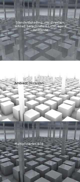
In 3D computer graphics, modeling, and animation, ambient occlusion is a shading and rendering technique used to calculate how exposed each point in a scene is to ambient lighting. For example, the interior of a tube is typically more occluded than the exposed outer surfaces, and becomes darker the deeper inside the tube one goes.

Beam tracing is an algorithm to simulate wave propagation. It was developed in the context of computer graphics to render 3D scenes, but it has been also used in other similar areas such as acoustics and electromagnetism simulations.

<span class="mw-page-title-main">Reflection mapping</span>

In computer graphics, reflection mapping or environment mapping is an efficient image-based lighting technique for approximating the appearance of a reflective surface by means of a precomputed texture. The texture is used to store the image of the distant environment surrounding the rendered object.

<span class="mw-page-title-main">Path tracing</span> Computer graphics method

Path tracing is a computer graphics Monte Carlo method of rendering images of three-dimensional scenes such that the global illumination is faithful to reality. Fundamentally, the algorithm is integrating over all the illuminance arriving to a single point on the surface of an object. This illuminance is then reduced by a surface reflectance function (BRDF) to determine how much of it will go towards the viewpoint camera. This integration procedure is repeated for every pixel in the output image. When combined with physically accurate models of surfaces, accurate models of real light sources, and optically correct cameras, path tracing can produce still images that are indistinguishable from photographs.

In computer graphics, per-pixel lighting refers to any technique for lighting an image or scene that calculates illumination for each pixel on a rendered image. This is in contrast to other popular methods of lighting such as vertex lighting, which calculates illumination at each vertex of a 3D model and then interpolates the resulting values over the model's faces to calculate the final per-pixel color values.

<span class="mw-page-title-main">3D rendering</span> Process of converting 3D scenes into 2D images

3D rendering is the 3D computer graphics process of converting 3D models into 2D images on a computer. 3D renders may include photorealistic effects or non-photorealistic styles.

The Blinn–Phong reflection model, also called the modified Phong reflection model, is a modification developed by Jim Blinn to the Phong reflection model.

In the field of 3D computer graphics, Multiple Render Targets, or MRT, is a feature of modern graphics processing units (GPUs) that allows the programmable rendering pipeline to render images to multiple render target textures at once. These textures can then be used as inputs to other shaders or as texture maps applied to 3D models. Introduced by OpenGL 2.0 and Direct3D 9, MRT can be invaluable to real-time 3D applications such as video games. Before the advent of MRT, a programmer would have to issue a command to the GPU to draw the 3D scene once for each render target texture, resulting in redundant vertex transformations which, in a real-time program expected to run as fast as possible, can be quite time-consuming. With MRT, a programmer creates a pixel shader that returns an output value for each render target. This pixel shader then renders to all render targets with a single draw command.

This is a glossary of terms relating to computer graphics.

References

  1. "Light: The art of exposure". GarageFarm. 2020-11-11. Retrieved 2020-11-11.
  2. 1 2 3 4 5 "Intro to Computer Graphics: Lighting and Shading". www.cs.uic.edu. Retrieved 2019-11-05.
  3. 1 2 "Intro to Computer Graphics: Lighting and Shading". www.cs.uic.edu. Retrieved 2019-11-05.
  4. 1 2 3 4 "Lighting in 3D Graphics". www.bcchang.com. Retrieved 2019-11-05.
  5. 1 2 3 "Understanding Different Light Types". www.pluralsight.com. Retrieved 2019-11-05.
  6. 1 2 3 4 "Intro to Computer Graphics: Lighting and Shading". www.cs.uic.edu. Retrieved 2019-11-05.
  7. Lagarde, Sebastien; de Rousiers, Charles (Summer 2014). Moving Frostbite to Physically Based Rendering 3.0. SIGGRAPH.
  8. Pharr, Matt; Humphreys, Greg; Wenzel, Jakob (2016). Physically Based Rendering: From Theory to Implementation (3rd ed.). Morgan Kaufmann. ISBN   978-0128006450.
  9. Vergne, Romain; Pacanowski, Romain; Barla, Pascal; Granier, Xavier; Schlick, Christophe (February 19, 2010). "Radiance Scaling for Versatile Surface Enhancement". Proceedings of the 2010 ACM SIGGRAPH symposium on Interactive 3D Graphics and Games. ACM. pp. 143–150. doi:10.1145/1730804.1730827. ISBN   9781605589398. S2CID   18291692 via hal.inria.fr.
  10. https://visao.ca/what-is-hdri/#:~:text=High%20dynamic%20range%20images%20are,look%20cartoonish%20and%20less%20professional.
  11. 1 2 "Lighting in 3D Graphics". www.bcchang.com. Retrieved 2019-11-05.
  12. 1 2 3 4 5 Pollard, Nancy (Spring 2004). "Lighting and Shading" (PDF).
  13. 1 2 3 "Lighting in 3D Graphics". www.bcchang.com. Retrieved 2019-11-05.
  14. 1 2 3 4 5 6 7 "LearnOpenGL - Basic Lighting". learnopengl.com. Retrieved 2019-11-08.
  15. "Intro to Computer Graphics: Lighting and Shading". www.cs.uic.edu. Retrieved 2019-11-08.
  16. 1 2 3 4 5 "Global Illumination" (PDF). Georgia Tech Classes. 2002.
  17. 1 2 3 4 5 Farrell. "Local Illumination". Kent University.
  18. 1 2 3 4 5 6 7 "Computer Graphics: Shading and Lighting". cglearn.codelight.eu. Retrieved 2019-10-30.
  19. 1 2 James F. Blinn (1977). "Models of light reflection for computer synthesized pictures". Proc. 4th annual conference on computer graphics and interactive techniques: 192–198. CiteSeerX 10.1.1.131.7741. doi : 10.1145/563858.563893
  20. Jacob's University, "Blinn-Phong Reflection Model", 2010.
  21. 1 2 3 4 Li, Hao (2018). "Shading in OpenGL" (PDF).
  22. 1 2 3 Li, Hao (Fall 2018). "Global Illumination" (PDF).
  23. "Introducing the NVIDIA RTX Ray Tracing Platform". NVIDIA Developer. 2018-03-06. Retrieved 2019-11-08.
  24. 1 2 Reif, J. H. (1994). "Computability and Complexity of Ray Tracing"(PDF). Discrete and Computational Geometry.
  25. 1 2 Wallace, John R.; Cohen, Michael F.; Greenberg, Donald P. (1987). "A Two-pass Solution to the Rendering Equation: A Synthesis of Ray Tracing and Radiosity Methods". Proceedings of the 14th Annual Conference on Computer Graphics and Interactive Techniques. SIGGRAPH '87. New York, NY, USA: ACM: 311–320. doi : 10.1145/37401.37438. ISBN   9780897912273.
  26. 1 2 Greenberg, Donald P. (1989-04-14). "Light Reflection Models for Computer Graphics". Science. 244 (4901): 166–173. Bibcode:1989Sci...244..166G. doi:10.1126/science.244.4901.166. ISSN   0036-8075. PMID   17835348. S2CID   46575183.
  27. Cindy Goral, Kenneth E. Torrance, Donald P. Greenberg and B. Battaile,"Modeling the interaction of light between diffuse surfaces", Computer Graphics , Vol. 18, No. 3. (PDF)
  28. 1 2 3 Wann Jensen, Henrik (1996). "Global Illumination using Photon Maps Archived 2008-08-08 at the Wayback Machine " (PDF). Rendering Techniques ’96: 21–30.
  29. 1 2 "Photon Mapping - Zack Waters". web.cs.wpi.edu. Retrieved 2019-11-08.
  30. "Introduction to Computer Graphics, Section 4.1 -- Introduction to Lighting". math.hws.edu.
  31. "Vertex Specification - OpenGL Wiki". www.khronos.org. Retrieved 2019-11-06.
  32. 1 2 3 4 5 6 Foley. "Illumination Models and Shading" (PDF).
  33. 1 2 3 "GPU Gems". NVIDIA Developer. Retrieved 2019-10-30.
  34. 1 2 3 "Caustics water texturing using Unity 3D". www.dualheights.se. Retrieved 2019-11-06.
  35. 1 2 "Computer Graphics: Environment Mapping". cglearn.codelight.eu. Retrieved 2019-11-01.
  36. Shen, Han-Wei. "Environment Mapping" (PDF).
  37. 1 2 3 4 Bailey, Mike. "Particle Systems" (PDF).
  38. "Particle Systems". web.cs.wpi.edu. Retrieved 2019-11-01.