Scanline rendering is an algorithm for visible surface determination, in 3D computer graphics, that works on a row-by-row basis rather than a polygon-by-polygon or pixel-by-pixel basis. All of the polygons to be rendered are first sorted by the top y coordinate at which they first appear, then each row or scan line of the image is computed using the intersection of a scanline with the polygons on the front of the sorted list, while the sorted list is updated to discard no-longer-visible polygons as the active scan line is advanced down the picture.

Gouraud shading, named after Henri Gouraud, is an interpolation method used in computer graphics to produce continuous shading of surfaces represented by polygon meshes. In practice, Gouraud shading is most often used to achieve continuous lighting on triangle meshes by computing the lighting at the corners of each triangle and linearly interpolating the resulting colours for each pixel covered by the triangle. Gouraud first published the technique in 1971.

Texture mapping is a method for mapping a texture on a computer-generated graphic. Texture here can be high frequency detail, surface texture, or color.

Shading refers to the depiction of depth perception in 3D models or illustrations by varying the level of darkness. Shading tries to approximate local behavior of light on the object's surface and is not to be confused with techniques of adding shadows, such as shadow mapping or shadow volumes, which fall under global behavior of light.

Ray casting is the methodological basis for 3D CAD/CAM solid modeling and image rendering. It is essentially the same as ray tracing for computer graphics where virtual light rays are "cast" or "traced" on their path from the focal point of a camera through each pixel in the camera sensor to determine what is visible along the ray in the 3D scene. The term "Ray Casting" was introduced by Scott Roth while at the General Motors Research Labs from 1978–1980. His paper, "Ray Casting for Modeling Solids", describes modeled solid objects by combining primitive solids, such as blocks and cylinders, using the set operators union (+), intersection (&), and difference (-). The general idea of using these binary operators for solid modeling is largely due to Voelcker and Requicha's geometric modelling group at the University of Rochester. See solid modeling for a broad overview of solid modeling methods. This figure on the right shows a U-Joint modeled from cylinders and blocks in a binary tree using Roth's ray casting system in 1979.
Solid modeling is a consistent set of principles for mathematical and computer modeling of three-dimensional shapes (solids). Solid modeling is distinguished within the broader related areas of geometric modeling and computer graphics, such as 3D modeling, by its emphasis on physical fidelity. Together, the principles of geometric and solid modeling form the foundation of 3D-computer-aided design and in general support the creation, exchange, visualization, animation, interrogation, and annotation of digital models of physical objects.

In 3D computer graphics and solid modeling, a polygon mesh is a collection of vertices, edges and faces that defines the shape of a polyhedral object. The faces usually consist of triangles, quadrilaterals (quads), or other simple convex polygons (n-gons), since this simplifies rendering, but may also be more generally composed of concave polygons, or even polygons with holes.

In computer graphics, a shader is a computer program that calculates the appropriate levels of light, darkness, and color during the rendering of a 3D scene—a process known as shading. Shaders have evolved to perform a variety of specialized functions in computer graphics special effects and video post-processing, as well as general-purpose computing on graphics processing units.
The computer graphics pipeline, also known as the rendering pipeline or graphics pipeline, is a fundamental framework within computer graphics that outlines the necessary procedures for transforming a three-dimensional (3D) scene into a two-dimensional (2D) representation on a screen. Once a 3D model is generated, whether it's for a video game or any other form of 3D computer animation, the graphics pipeline becomes instrumental in converting the model into a visually perceivable format on the computer display. Due to the dependence on specific software, hardware configurations, and desired display attributes, a universally applicable graphics pipeline does not exist. Nevertheless, graphics application programming interfaces (APIs), such as Direct3D and OpenGL, were developed to standardize common procedures and oversee the graphics pipeline of a given hardware accelerator. These APIs provide an abstraction layer over the underlying hardware, relieving programmers from the need to write code explicitly targeting various graphics hardware accelerators like AMD, Intel, Nvidia, and others.
Real-time computer graphics or real-time rendering is the sub-field of computer graphics focused on producing and analyzing images in real time. The term can refer to anything from rendering an application's graphical user interface (GUI) to real-time image analysis, but is most often used in reference to interactive 3D computer graphics, typically using a graphics processing unit (GPU). One example of this concept is a video game that rapidly renders changing 3D environments to produce an illusion of motion.
In 3D computer graphics, polygonal modeling is an approach for modeling objects by representing or approximating their surfaces using polygon meshes. Polygonal modeling is well suited to scanline rendering and is therefore the method of choice for real-time computer graphics. Alternate methods of representing 3D objects include NURBS surfaces, subdivision surfaces, and equation-based representations used in ray tracers.
Clipping, in the context of computer graphics, is a method to selectively enable or disable rendering operations within a defined region of interest. Mathematically, clipping can be described using the terminology of constructive geometry. A rendering algorithm only draws pixels in the intersection between the clip region and the scene model. Lines and surfaces outside the view volume are removed.

STL is a file format native to the stereolithography CAD software created by 3D Systems. Chuck Hull, the inventor of stereolithography and 3D Systems’ founder, reports that the file extension is an abbreviation for stereolithography.
3D rendering is the 3D computer graphics process of converting 3D models into 2D images on a computer. 3D renders may include photorealistic effects or non-photorealistic styles.
3D computer graphics, sometimes called CGI, 3D-CGI or three-dimensional computer graphics, are graphics that use a three-dimensional representation of geometric data that is stored in the computer for the purposes of performing calculations and rendering digital images, usually 2D images but sometimes 3D images. The resulting images may be stored for viewing later or displayed in real time.

A vertex in computer graphics is a data structure that describes certain attributes, like the position of a point in 2D or 3D space, or multiple points on a surface.

Cobalt is a parametric-based computer-aided design (CAD) and 3D modeling program that runs on both Macintosh and Microsoft Windows operating systems. The program combines the direct-modeling way to create and edit objects and the highly structured, history-driven parametric way exemplified by programs like Pro/ENGINEER. A product of Ashlar-Vellum, Cobalt is Wireframe-based and history-driven with associativity and 2D equation-driven parametrics and constraints. It offers surfacing tools, mold design tools, detailing, and engineering features. Cobalt includes a library of 149,000 mechanical parts.
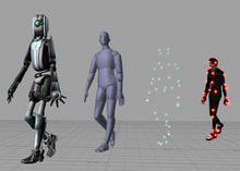
In 3D computer graphics, 3D modeling is the process of developing a mathematical coordinate-based representation of any surface of an object in three dimensions via specialized software by manipulating edges, vertices, and polygons in a simulated 3D space.
Additive manufacturing file format (AMF) is an open standard for describing objects for additive manufacturing processes such as 3D printing. The official ISO/ASTM 52915:2016 standard is an XML-based format designed to allow any computer-aided design software to describe the shape and composition of any 3D object to be fabricated on any 3D printer via a computer-aided manufacturing software. Unlike its predecessor STL format, AMF has native support for color, materials, lattices, and constellations.
This is a glossary of terms relating to computer graphics.