
An envelope detector (sometimes called a peak detector) is an electronic circuit that takes a (relatively) high-frequency amplitude modulated signal as input and provides an output, which is the demodulated envelope of the original signal.
An envelope detector (sometimes called a peak detector) is an electronic circuit that takes a (relatively) high-frequency amplitude modulated signal as input and provides an output, which is the demodulated envelope of the original signal.
A simple form of envelope detector used in detectors for early radios is the diode detector. Its output approximates a voltage-shifted version of the upper envelope.
Between the circuit's input and output is a diode that performs half-wave rectification, allowing substantial current flow only when the input voltage is around a diode drop higher than the output terminal.
The output is connected to a capacitor and resistor in parallel to ground. The capacitor is charged as the input voltage approaches its positive peaks. At other times, the capacitor is gradually discharged through the resistor. The resistor and capacitor form a 1st-order low pass filter, which attenuates higher frequencies at a rate of -6 dB per octave above its cutoff frequency. The filter's RC time constant must be small enough to track quickly-falling envelope slopes.
Envelope detectors can be used to demodulate an amplitude modulated (AM) signal. Such a device is often used to demodulate AM radio signals because the envelope of the modulated signal is equivalent to the baseband signal. To sufficiently attenuate the frequency of the carrier wave used for modulation, the cutoff frequency of the low-pass filter should be well-below the carrier wave's frequency. To filter out the DC component, the output could next pass through a simple high-pass filter, such as a DC-blocking capacitor.
Most practical envelope detectors use either half-wave or full-wave rectification of the signal to convert the AC audio input into a pulsed DC signal. Full-wave rectification traces both positive an negative peaks of the envelope. Half-wave rectification ignores negative peaks, which may be acceptable based on the application, particularly if the input signal is symmetric about the horizontal axis. Low threshold voltage diodes (e.g. germanium or Schottky diodes) may be preferable for tracking very small envelopes.
The filtering for smoothing the final result is rarely perfect and some "ripple" is likely to remain on the output, particularly for low frequency inputs such from a bass instrument. Reducing the filter cutoff frequency gives a smoother output, but designers must compromise this with the circuit's high frequency response.

Any AM or FM signal can be written in the following form
In the case of AM, φ(t) (the phase component of the signal) is constant and can be ignored. In AM, the carrier frequency is also constant. Thus, all the information in the AM signal is in R(t). R(t) is called the envelope of the signal. Hence an AM signal is given by the function
with m(t) representing the original audio frequency message, C the carrier amplitude and R(t) equal to C + m(t). So, if the envelope of the AM signal can be extracted, the original message can be recovered.
In the case of FM, the transmitted has a constant envelope R(t) = R and can be ignored. However, many FM receivers measure the envelope anyway for received signal strength indication.
An envelope detector can also be constructed using a precision rectifier feeding into a low-pass filter.
The envelope detector has several drawbacks:
Most of these drawbacks are relatively minor and are usually acceptable tradeoffs for the simplicity and low cost of using an envelope detector.
An envelope detector is sometimes referred to as an envelope follower in musical environments. It is still used to detect the amplitude variations of an incoming signal to produce a control signal that resembles those variations. However, in this case the input signal is made up of audible frequencies.
Envelope detectors are often a component of other circuits, such as a compressor or an auto-wah or envelope-followed filter. In these circuits, the envelope follower is part of what is known as the "side chain", a circuit which describes some characteristic of the input, in this case its volume.
Both expanders and compressors use the envelope's output voltage to control the gain of an amplifier. Auto-wah uses the voltage to control the cutoff frequency of a filter. The voltage-controlled filter of an analog synthesizer is a similar circuit.
Modern envelope followers can be implemented:
An electronic oscillator is an electronic circuit that produces a periodic, oscillating or alternating current (AC) signal, usually a sine wave, square wave or a triangle wave, powered by a direct current (DC) source. Oscillators are found in many electronic devices, such as radio receivers, television sets, radio and television broadcast transmitters, computers, computer peripherals, cellphones, radar, and many other devices.
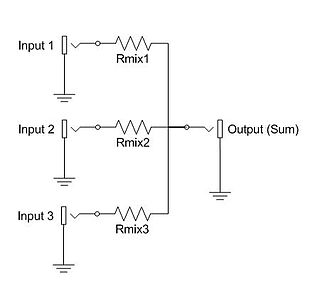
An electronic mixer is a device that combines two or more electrical or electronic signals into one or two composite output signals. There are two basic circuits that both use the term mixer, but they are very different types of circuits: additive mixers and multiplicative mixers. Additive mixers are also known as analog adders to distinguish from the related digital adder circuits.
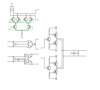
A phase-locked loop or phase lock loop (PLL) is a control system that generates an output signal whose phase is fixed relative to the phase of an input signal. Keeping the input and output phase in lockstep also implies keeping the input and output frequencies the same, thus a phase-locked loop can also track an input frequency. And by incorporating a frequency divider, a PLL can generate a stable frequency that is a multiple of the input frequency.
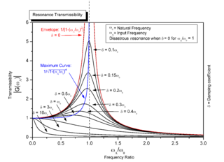
Resonance occurs in an oscillatory dynamical systems when an external, time-varying force coincides with the a natural frequency of the system. Resonance can occur in various systems, such as mechanical, electrical, or acoustic systems, and it is desirable in certain applications, such as musical instruments or radio receivers. Resonance can also be undesirable, leading to excessive vibrations or even structural failure in some cases.
A low-pass filter is a filter that passes signals with a frequency lower than a selected cutoff frequency and attenuates signals with frequencies higher than the cutoff frequency. The exact frequency response of the filter depends on the filter design. The filter is sometimes called a high-cut filter, or treble-cut filter in audio applications. A low-pass filter is the complement of a high-pass filter.

A rectifier is an electrical device that converts alternating current (AC), which periodically reverses direction, to direct current (DC), which flows in only one direction. The reverse operation is performed by an inverter.
Demodulation is extracting the original information-bearing signal from a carrier wave. A demodulator is an electronic circuit that is used to recover the information content from the modulated carrier wave. There are many types of modulation so there are many types of demodulators. The signal output from a demodulator may represent sound, images or binary data.

In electronics, ring modulation is a signal processing function, an implementation of frequency mixing, in which two signals are combined to yield an output signal. One signal, called the carrier, is typically a sine wave or another simple waveform; the other signal is typically more complicated and is called the input or the modulator signal. A ring modulator is an electronic device for ring modulation. A ring modulator may be used in music synthesizers and as an effects unit.
A resistor–capacitor circuit, or RC filter or RC network, is an electric circuit composed of resistors and capacitors. It may be driven by a voltage or current source and these will produce different responses. A first order RC circuit is composed of one resistor and one capacitor and is the simplest type of RC circuit.
A product detector is a type of demodulator used for AM and SSB signals. Rather than converting the envelope of the signal into the decoded waveform like an envelope detector, the product detector takes the product of the modulated signal and a local oscillator, hence the name. A product detector is a frequency mixer.
A phase detector or phase comparator is a frequency mixer, analog multiplier or logic circuit that generates a signal which represents the difference in phase between two signal inputs.

In electronics, a mixer, or frequency mixer, is an electrical circuit that creates new frequencies from two signals applied to it. In its most common application, two signals are applied to a mixer, and it produces new signals at the sum and difference of the original frequencies. Other frequency components may also be produced in a practical frequency mixer.

The Foster–Seeley discriminator is a common type of FM detector circuit, invented in 1936 by Dudley E. Foster and Stuart William Seeley. The Foster–Seeley discriminator was envisioned for automatic frequency control of receivers, but also found application in demodulating an FM signal.
Linear electronic oscillator circuits, which generate a sinusoidal output signal, are composed of an amplifier and a frequency selective element, a filter. A linear oscillator circuit which uses an RC network, a combination of resistors and capacitors, for its frequency selective part is called an RC oscillator.
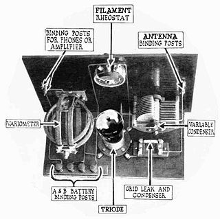
A grid leak detector is an electronic circuit that demodulates an amplitude modulated alternating current and amplifies the recovered modulating voltage. The circuit utilizes the non-linear cathode to control grid conduction characteristic and the amplification factor of a vacuum tube. Invented by Lee De Forest around 1912, it was used as the detector (demodulator) in the first vacuum tube radio receivers until the 1930s.
Ripple in electronics is the residual periodic variation of the DC voltage within a power supply which has been derived from an alternating current (AC) source. This ripple is due to incomplete suppression of the alternating waveform after rectification. Ripple voltage originates as the output of a rectifier or from generation and commutation of DC power.

In radio, a detector is a device or circuit that extracts information from a modulated radio frequency current or voltage. The term dates from the first three decades of radio (1888–1918). Unlike modern radio stations which transmit sound on an uninterrupted carrier wave, early radio stations transmitted information by radiotelegraphy. The transmitter was switched on and off to produce long or short periods of radio waves, spelling out text messages in Morse code. Therefore, early radio receivers did not have to demodulate the radio signal, but just distinguish between the presence or absence of a radio signal, to reproduce the Morse code "dots" and "dashes". The device that performed this function in the receiver circuit was called a detector. A variety of different detector devices, such as the coherer, electrolytic detector, magnetic detector and the crystal detector, were used during the wireless telegraphy era until superseded by vacuum tube technology.
In electronics, a differentiator is a circuit that outputs a signal approximately proportional to the rate of change of its input signal. Because the derivative of a sinusoid in another sinusoid whose amplitude is multiplied by its frequency, a true differentiator that works across all frequencies can't be realized. Real circuits such as a 1st-order high-pass filter are able to approximate differentiation at lower frequencies by limiting the gain above its cutoff frequency. An active differentiator includes an amplifier, while a passive differentiator is made only of resistors, capacitors and inductors.

In electronics, a plate detector is a vacuum tube circuit in which an amplifying tube having a control grid is operated in a non-linear region of its grid voltage versus plate current transfer characteristic, usually near plate current cutoff, to demodulate amplitude modulated carrier signal. This differs from the grid leak detector, which utilizes the non-linearity of the grid voltage versus grid current characteristic for demodulation. It also differs from the diode detector, which is a two-terminal device.

The ratio detector is a type of detector circuit, commonly used in radio receivers for demodulating frequency modulated (FM) signal.


