Induction generator

Last updated

An induction generator or asynchronous generator is a type of alternating current (AC) electrical generator that uses the principles of induction motors to produce electric power. Induction generators operate by mechanically turning their rotors faster than synchronous speed. A regular AC induction motor usually can be used as a generator, without any internal modifications. Because they can recover energy with relatively simple controls, induction generators are useful in applications such as mini hydro power plants, wind turbines, or in reducing high-pressure gas streams to lower pressure.

Contents

An induction generator draws reactive excitation current from an external source. Induction generators have an AC rotor and cannot bootstrap using residual magnetization to black start a de-energized distribution system as synchronous machines do. Power factor correcting capacitors can be added externally to neutralize a constant amount of the variable reactive excitation current. After starting, an induction generator can use a capacitor bank to produce reactive excitation current, but the isolated power system’s voltage and frequency are not self-regulating and destabilize readily.

Principle of operation

An induction generator produces electrical power when its rotor is turned faster than the synchronous speed. For a four-pole motor (two pairs of poles on stator) powered by a 60 Hz source, the synchronous speed is 1800 rotations per minute (rpm) and 1500 RPM powered at 50 Hz. The motor always turns slightly slower than the synchronous speed. The difference between synchronous and operating speed is called "slip" and is often expressed as per cent of the synchronous speed. For example, a motor operating at 1450 RPM that has a synchronous speed of 1500 RPM is running at a slip of +3.3%.

In operation as a motor, the stator flux rotation is at the synchronous speed, which is faster than the rotor speed. This causes the stator flux to cycle at the slip frequency inducing rotor current through the mutual inductance between the stator and rotor. The induced current create a rotor flux with magnetic polarity opposite to the stator. In this way, the rotor is dragged along behind stator flux, with the currents in the rotor induced at the slip frequency. The motor runs at the speed where the induced rotor current gives rise to torque equal to the shaft load.

In generator operation, a prime mover (turbine or engine) drives the rotor above the synchronous speed (negative slip). The stator flux induces current in the rotor, but the opposing rotor flux is now cutting the stator coils, a current is induced in the stator coils 270° behind the magnetizing current, in phase with magnetizing voltage. The motor delivers real (in-phase) power to the power system.

Excitation

Equivalent circuit of induction generator Asynch-esb-2.svg
Equivalent circuit of induction generator

An induction motor requires an externally supplied current to the stator windings in order to induce a current in the rotor. Because the current in an inductor is integral of the voltage with respect to time, for a sinusoidal voltage waveform the current lags the voltage by 90°, and the induction motor always consumes reactive power, regardless of whether it is consuming electrical power and delivering mechanical power as a motor or consuming mechanical power and delivering electrical power to the system.

A source of excitation current for magnetizing flux (reactive power) for the stator is still required, to induce rotor current. This can be supplied from the electrical grid or, once it starts producing power, from a capacitive reactance. The generating mode for induction motors is complicated by the need to excite the rotor, which being induced by an alternating current is demagnetized at shutdown with no residual magnetization to bootstrap a cold start. It is necessary to connect an external source of magnetizing current to initialize production. The power frequency and voltage are not self regulating. The generator is able to supply current out of phase with the voltage requiring more external equipment to build a functional isolated power system. Similar is the operation of the induction motor in parallel with a synchronous motor serving as a power factor compensator. A feature in the generator mode in parallel to the grid is that the rotor speed is higher than in the driving mode. Then active energy is being given to the grid. [1] Another disadvantage of induction motor generator is that it consumes a significant magnetizing current I0 = (20-35)%.

Active power

Active power delivered to the line is proportional to slip above the synchronous speed. Full rated power of the generator is reached at very small slip values (motor dependent, typically 3%). At synchronous speed of 1800 RPM, generator will produce no power. When the driving speed is increased to 1860 RPM (typical example), full output power is produced. If the prime mover is unable to produce enough power to fully drive the generator, speed will remain somewhere between 1800 and 1860 RPM range.

Required capacitance

A capacitor bank must supply reactive power to the motor when used in stand-alone mode. The reactive power supplied should be equal or greater than the reactive power that the generator normally draws when operating as a motor.

Torque vs. slip

The basic fundamental of induction generators is the conversion from mechanical energy to electrical energy. This requires an external torque applied to the rotor to turn it faster than the synchronous speed. However, indefinitely increasing torque doesn't lead to an indefinite increase in power generation. The rotating magnetic field torque excited from the armature works to counter the motion of the rotor and prevent over speed because of induced motion in the opposite direction. As the speed of the motor increases the counter torque reaches a max value of torque (breakdown torque) that it can operate until before the operating conditions become unstable. Ideally, induction generators work best in the stable region between the no-load condition and maximum torque region.

Rated current

The maximum power that can be produced by an induction motor operated as a generator is limited by the rated current of the generator's windings.

Grid and stand-alone connections

Typical connections when used as a standalone generator Capacitor excited asynchronous generator with load.svg
Typical connections when used as a standalone generator

In induction generators, the reactive power required to establish the air gap magnetic flux is provided by a capacitor bank connected to the machine in case of stand-alone system and in case of grid connection it draws reactive power from the grid to maintain its air gap flux. For a grid-connected system, frequency and voltage at the machine will be dictated by the electric grid, since it is very small compared to the whole system. For stand-alone systems, frequency and voltage are complex function of machine parameters, capacitance used for excitation, and load value and type.

Uses

Induction generators are often used in wind turbines and some micro hydro installations due to their ability to produce useful power at varying rotor speeds. Induction generators are mechanically and electrically simpler than other generator types. They are also more rugged, requiring no brushes or commutators.

Limitations

An induction generator connected to a capacitor system can generate sufficient reactive power to operate on its own. When the load current exceeds the capability of the generator to supply both magnetization reactive power and load power the generator will immediately cease to produce power. In other wording: the slip (s) from negative "slides" into zero (0) and this sets the induction machine "at the brink" to exit the generator mode and ready to enter the motor mode. Further the "positivization" of slip (s) drives the induction asynchronous machine into the motor mode. Consequence: power flow switches direction (sense!): induction machine consumes power form gird instead of delivering it. The load must be removed and the induction generator restarted with either a external DC motor, or if present, residual magnetism in the core. [2]

Induction generators are particularly suitable for wind generating stations as in this case speed is always a variable factor. Unlike synchronous motors, induction generators are load-dependent and cannot be used alone for grid frequency control.

Example application

As an example, consider the use of a 10 hp, 1760 r/min, 440 V, three-phase induction motor (a.k.a. induction electrical machine in an asynchronous generator regime) as asynchronous generator. The full-load current of the motor is 10 A and the full-load power factor is 0.8.

Required capacitance per phase if capacitors are connected in delta:

Apparent power
Active power
Reactive power

For a machine to run as an asynchronous generator, capacitor bank must supply minimum 4567 / 3 phases = 1523 VAR per phase. Voltage per capacitor is 440 V because capacitors are connected in delta.

Capacitive current Ic = Q/E = 1523/440 = 3.46 A
Capacitive reactance per phase Xc = E/Ic = 127 Ω

Minimum capacitance per phase:

C = 1 / (2*π*f*Xc) = 1 / (2 * 3.141 * 60 * 127) = 21 µF.

If the load also absorbs reactive power, capacitor bank must be increased in size to compensate.

Prime mover speed should be used to generate frequency of 60 Hz:

Typically, slip should be similar to full-load value when machine is running as motor, but negative (generator operation):

if Ns = 1800, one can choose N=Ns+40 rpm
Required prime mover speed N = 1800 + 40 = 1840 rpm.

See also

Notes

  1. Babbage, C.; Herschel, J. F. W. (Jan 1825). "Account of the Repetition of M. Arago's Experiments on the Magnetism Manifested by Various Substances during the Act of Rotation". Philosophical Transactions of the Royal Society. 115: 467–496. doi: 10.1098/rstl.1825.0023 . Retrieved 2 December 2012.
  2. Huassain, Ashfaq. Electric Machines. Dhanpat Rai and Co. p. 411.

Related Research Articles

<span class="mw-page-title-main">Electric motor</span> Machine that converts electrical energy into mechanical energy

An electric motor is an electrical machine that converts electrical energy into mechanical energy. Most electric motors operate through the interaction between the motor's magnetic field and electric current in a wire winding to generate force in the form of torque applied on the motor's shaft. An electric generator is mechanically identical to an electric motor, but operates in reverse, converting mechanical energy into electrical energy.

<span class="mw-page-title-main">Electric generator</span> Device that converts other energy to electrical energy

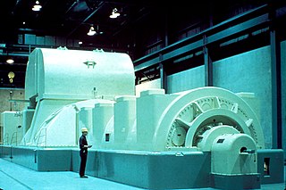
In electricity generation, a generator is a device that converts motion-based power or fuel-based power into electric power for use in an external circuit. Sources of mechanical energy include steam turbines, gas turbines, water turbines, internal combustion engines, wind turbines and even hand cranks. The first electromagnetic generator, the Faraday disk, was invented in 1831 by British scientist Michael Faraday. Generators provide nearly all the power for electrical grids.

<span class="mw-page-title-main">Alternator</span> Device converting mechanical into electrical energy

An alternator is an electrical generator that converts mechanical energy to electrical energy in the form of alternating current. For reasons of cost and simplicity, most alternators use a rotating magnetic field with a stationary armature. Occasionally, a linear alternator or a rotating armature with a stationary magnetic field is used. In principle, any AC electrical generator can be called an alternator, but usually the term refers to small rotating machines driven by automotive and other internal combustion engines.

<span class="mw-page-title-main">Induction motor</span> Type of AC electric motor

An induction motor or asynchronous motor is an AC electric motor in which the electric current in the rotor that produces torque is obtained by electromagnetic induction from the magnetic field of the stator winding. An induction motor therefore needs no electrical connections to the rotor. An induction motor's rotor can be either wound type or squirrel-cage type.

<span class="mw-page-title-main">Synchronous motor</span> Type of AC motor

A synchronous electric motor is an AC electric motor in which, at steady state, the rotation of the shaft is synchronized with the frequency of the supply current; the rotation period is exactly equal to an integral number of AC cycles. Synchronous motors use electromagnets as the stator of the motor which create a magnetic field that rotates in time with the oscillations of the current. The rotor with permanent magnets or electromagnets turns in step with the stator field at the same rate and as a result, provides the second synchronized rotating magnet field. A synchronous motor is termed doubly fed if it is supplied with independently excited multiphase AC electromagnets on both the rotor and stator.

<span class="mw-page-title-main">Squirrel-cage rotor</span> Rotating part of the common squirrel-cage induction motor

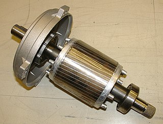
A squirrel-cage rotor is the rotating part of the common squirrel-cage induction motor. It consists of a cylinder of steel laminations, with aluminum or copper conductors embedded in its surface. In operation, the non-rotating stator winding is connected to an alternating current power source; the alternating current in the stator produces a rotating magnetic field. The rotor winding has current induced in it by the stator field, like a transformer except that the current in the rotor is varying at the stator field rotation rate minus the physical rotation rate. The interaction of the magnetic fields of currents in the stator and rotor produce a torque on the rotor.

<span class="mw-page-title-main">Shaded-pole motor</span> Type of AC single-phase induction motor

The shaded-pole motor is the original type of AC single-phase motor, dating back to at least as early as 1890. A shaded-pole motor is a small motor with either two or four poles, in which the auxiliary winding is composed of a copper ring or bar surrounding a portion of each pole to produce a weakly rotating magnetic field. When single phase AC supply is applied to the stator winding, due to shading provided to the poles, a rotating magnetic field is generated. This auxiliary single-turn winding is called a shading coil. Currents induced in this coil by the magnetic field create a second electrical phase by delaying the phase of magnetic flux change for that pole enough to provide a 2-phase rotating magnetic field. The direction of rotation is from the unshaded side to the shaded (ring) side of the pole. Since the phase angle between the shaded and unshaded sections is small, shaded-pole motors produce only a small starting torque relative to torque at full speed. Shaded-pole motors of the asymmetrical type shown are only reversible by disassembly and flipping over the stator, though some similar looking motors have small, switch-shortable auxiliary windings of thin wire instead of thick copper bars and can reverse electrically. Another method of electrical reversing involves four coils.

<span class="mw-page-title-main">Variable-frequency drive</span> Type of adjustable-speed drive

A variable-frequency drive is a type of AC motor drive that controls speed and torque by varying the frequency of the input electricity. Depending on its topology, it controls the associated voltage or current variation.

A variable-frequency transformer (VFT) is used to transmit electricity between two alternating current frequency domains. The VFT is a relatively recent development. Most asynchronous grid inter-ties use high-voltage direct current converters, while synchronous grid inter-ties are connected by lines and "ordinary" transformers, but without the ability to control power flow between the systems, or with phase-shifting transformer with some flow control.

<span class="mw-page-title-main">Synchronous condenser</span> Machinery used to adjust conditions on the electric power transmission grid

In electrical engineering, a synchronous condenser is a DC-excited synchronous motor, whose shaft is not connected to anything but spins freely. Its purpose is not to convert electric power to mechanical power or vice versa, but to adjust conditions on the electric power transmission grid. Its field is controlled by a voltage regulator to either generate or absorb reactive power as needed to adjust the grid's voltage, or to improve power factor. The condenser’s installation and operation are identical to large electric motors and generators.

<span class="mw-page-title-main">Rotary phase converter</span> Electrical machine

A rotary phase converter, abbreviated RPC, is an electrical machine that converts power from one polyphase system to another, converting through rotary motion. Typically, single-phase electric power is used to produce three-phase electric power locally to run three-phase loads in premises where only single-phase is available.

<span class="mw-page-title-main">AC motor</span> Electric motor driven by an AC electrical input

An AC motor is an electric motor driven by an alternating current (AC). The AC motor commonly consists of two basic parts, an outside stator having coils supplied with alternating current to produce a rotating magnetic field, and an inside rotor attached to the output shaft producing a second rotating magnetic field. The rotor magnetic field may be produced by permanent magnets, reluctance saliency, or DC or AC electrical windings.

Doubly fed electric machines, also slip-ring generators, are electric motors or electric generators, where both the field magnet windings and armature windings are separately connected to equipment outside the machine.

<span class="mw-page-title-main">Rotor (electric)</span> Non-stationary part of a rotary electric motor

The rotor is a moving component of an electromagnetic system in the electric motor, electric generator, or alternator. Its rotation is due to the interaction between the windings and magnetic fields which produces a torque around the rotor's axis.

In electrical engineering, electric machine is a general term for machines using electromagnetic forces, such as electric motors, electric generators, and others. They are electromechanical energy converters: an electric motor converts electricity to mechanical power while an electric generator converts mechanical power to electricity. The moving parts in a machine can be rotating or linear. Besides motors and generators, a third category often included is transformers, which although they do not have any moving parts are also energy converters, changing the voltage level of an alternating current.

<span class="mw-page-title-main">Excitation (magnetic)</span> Generation of a magnetic field by an electric current

In electromagnetism, excitation is the process of generating a magnetic field by means of an electric current.

<span class="mw-page-title-main">Switched reluctance motor</span> Externally controlled electric motor that runs by reluctance torque

The switched reluctance motor (SRM) is an electric motor that runs by reluctance torque and thus is a subgroup in reluctance motors. Unlike common brushed DC motor types, power is delivered to windings in the stator (case) rather than the rotor. This greatly simplifies mechanical design as power does not have to be delivered to a moving part which eliminates the need for a commutator, but it complicates the electrical design as some sort of switching system needs to be used to deliver power to the different windings. Electronic devices can precisely time the switching of currents, facilitating SRM configurations. Its main drawback is torque ripple. Controller technology that limits torque ripple at low speeds has been demonstrated. Sources disagree on whether it is a type of stepper motor.

A permanent magnet synchronous generator is a generator where the excitation field is provided by a permanent magnet instead of a coil. The term synchronous refers here to the fact that the rotor and magnetic field rotate with the same speed, because the magnetic field is generated through a shaft mounted permanent magnet mechanism and current is induced into the stationary armature.

<span class="mw-page-title-main">Circle diagram</span>

The circle diagram is the graphical representation of the performance of the electrical machine drawn in terms of the locus of the machine's input voltage and current. It was first conceived by Alexander Heyland in 1894 and Bernhard Arthur Behrend in 1895. A newer variant devised by Johann Ossanna in 1899 is often named Ossanna diagram, Ossanna circle, Heyland-Ossanna diagram or Heyland-Ossanna circle. In 1910, Josef Sumec further improved the diagram by also incorporating the rotor resistance, then called Sumec diagram or Sumec circle.

Electromagnetically induced acoustic noise (and vibration), electromagnetically excited acoustic noise, or more commonly known as coil whine, is audible sound directly produced by materials vibrating under the excitation of electromagnetic forces. Some examples of this noise include the mains hum, hum of transformers, the whine of some rotating electric machines, or the buzz of fluorescent lamps. The hissing of high voltage transmission lines is due to corona discharge, not magnetism.

References