Induction motor

Last updated

Three-phase totally-enclosed fan-cooled (TEFC) induction motor with end cover on the left, and without end cover to show cooling fan on the right. In TEFC motors, interior heat losses are dissipated indirectly through enclosure fins, mostly by forced air convection. Silniki by Zureks.jpg
Three-phase totally-enclosed fan-cooled (TEFC) induction motor with end cover on the left, and without end cover to show cooling fan on the right. In TEFC motors, interior heat losses are dissipated indirectly through enclosure fins, mostly by forced air convection.
Cutaway view through stator of TEFC induction motor, showing rotor with internal air circulation vanes. Many such motors have a symmetric armature, and the frame may be reversed to place the electrical connection box (not shown) on the opposite side. Rotterdam Ahoy Europort 2011 (14).JPG
Cutaway view through stator of TEFC induction motor, showing rotor with internal air circulation vanes. Many such motors have a symmetric armature, and the frame may be reversed to place the electrical connection box (not shown) on the opposite side.

An induction motor or asynchronous motor is an AC electric motor in which the electric current in the rotor that produces torque is obtained by electromagnetic induction from the magnetic field of the stator winding. [1] An induction motor therefore needs no electrical connections to the rotor. [lower-alpha 1] An induction motor's rotor can be either wound type or squirrel-cage type.

Contents

Three-phase squirrel-cage induction motors are widely used as industrial drives because they are self-starting, reliable, and economical. Single-phase induction motors are used extensively for smaller loads, such as garbage disposals and stationary power tools. Although traditionally used for constant-speed service, single- and three-phase induction motors are increasingly being installed in variable-speed applications using variable-frequency drives (VFD). VFD offers energy savings opportunities for induction motors in applications like fans, pumps, and compressors that have a variable load.

History

A model of Nikola Tesla's first induction motor at the Tesla Museum in Belgrade, Serbia Tesla's induction motor.jpg
A model of Nikola Tesla's first induction motor at the Tesla Museum in Belgrade, Serbia
Squirrel-cage rotor construction, showing only the center three laminations Squirrel cage.jpg
Squirrel-cage rotor construction, showing only the center three laminations

In 1824, the French physicist François Arago formulated the existence of rotating magnetic fields, termed Arago's rotations. By manually turning switches on and off, Walter Baily demonstrated this in 1879, effectively the first primitive induction motor. [2] [3] [4] [5] [6] [7] [8]

The first commutator-free single-phase AC induction motor was invented by Hungarian engineer Ottó Bláthy; he used the single-phase motor to propel his invention, the electricity meter. [9] [10]

The first AC commutator-free polyphase induction motors were independently invented by Galileo Ferraris and Nikola Tesla, a working motor model having been demonstrated by the former in 1885 and by the latter in 1887. Tesla applied for US patents in October and November 1887 and was granted some of these patents in May 1888. In April 1888, the Royal Academy of Science of Turin published Ferraris's research on his AC polyphase motor detailing the foundations of motor operation. [5] [11] In May 1888 Tesla presented the technical paper A New System for Alternating Current Motors and Transformers to the American Institute of Electrical Engineers (AIEE) [12] [13] [14] [15] [16] describing three four-stator-pole motor types: one having a four-pole rotor forming a non-self-starting reluctance motor, another with a wound rotor forming a self-starting induction motor, and the third a true synchronous motor with a separately excited DC supply to the rotor winding.

George Westinghouse, who was developing an alternating current power system at that time, licensed Tesla's patents in 1888 and purchased a US patent option on Ferraris' induction motor concept. [17] Tesla was also employed for one year as a consultant. Westinghouse employee C. F. Scott was assigned to assist Tesla and later took over development of the induction motor at Westinghouse. [12] [18] [19] [20] Steadfast in his promotion of three-phase development, Mikhail Dolivo-Dobrovolsky invented the cage-rotor induction motor in 1889 and the three-limb transformer in 1890. [21] [22] Furthermore, he claimed that Tesla's motor was not practical because of two-phase pulsations, which prompted him to persist in his three-phase work. [23] Although Westinghouse achieved its first practical induction motor in 1892 and developed a line of polyphase 60 hertz induction motors in 1893, these early Westinghouse motors were two-phase motors with wound rotors until B. G. Lamme developed a rotating bar winding rotor. [12]

The General Electric Company (GE) began developing three-phase induction motors in 1891. [12] By 1896, General Electric and Westinghouse signed a cross-licensing agreement for the bar-winding-rotor design, later called the squirrel-cage rotor. [12] Arthur E. Kennelly was the first to bring out the full significance of complex numbers (using j to represent the square root of minus one) to designate the 90º rotation operator in analysis of AC problems. [24] GE's Charles Proteus Steinmetz improved the application of AC complex quantities and developed an analytical model called the induction motor Steinmetz equivalent circuit. [12] [25] [26] [27]

Induction motor improvements flowing from these inventions and innovations were such that a modern 100-horsepower induction motor has the same mounting dimensions as a 7.5-horsepower motor in 1897. [12]

Principle

3-phase motor

A three-phase power supply provides a rotating magnetic field in an induction motor. Rotatingfield.png
A three-phase power supply provides a rotating magnetic field in an induction motor.
Inherent slip - unequal rotation frequency of stator field and the rotor Asynchronmotor animation.gif
Inherent slip – unequal rotation frequency of stator field and the rotor

In both induction and synchronous motors, the AC power supplied to the motor's stator creates a magnetic field that rotates in synchronism with the AC oscillations. Whereas a synchronous motor's rotor turns at the same rate as the stator field, an induction motor's rotor rotates at a somewhat slower speed than the stator field. The induction motor stator's magnetic field is therefore changing or rotating relative to the rotor. This induces an opposing current in the rotor, in effect the motor's secondary winding. [28] The rotating magnetic flux induces currents in the rotor windings, [29] in a manner similar to currents induced in a transformer's secondary winding(s).

The induced currents in the rotor windings in turn create magnetic fields in the rotor that react against the stator field. The direction of the rotor magnetic field opposes the change in current through the rotor windings, following Lenz's Law. The cause of induced current in the rotor windings is the rotating stator magnetic field, so to oppose the change in rotor-winding currents the rotor turns in the direction of the stator magnetic field. The rotor accelerates until the magnitude of induced rotor current and torque balances the load on the rotor. Since rotation at synchronous speed does not induce rotor current, an induction motor always operates slightly slower than synchronous speed. The difference, or "slip," between actual and synchronous speed varies from about 0.5% to 5.0% for standard Design B torque curve induction motors. [30] The induction motor's essential character is that torque is created solely by induction instead of the rotor being separately excited as in synchronous or DC machines or being self-magnetized as in permanent magnet motors. [28]

For rotor currents to be induced, the speed of the physical rotor must be lower than that of the stator's rotating magnetic field (); otherwise the magnetic field would not be moving relative to the rotor conductors and no currents would be induced. As the speed of the rotor drops below synchronous speed, the rotation rate of the magnetic field in the rotor increases, inducing more current in the windings and creating more torque. The ratio between the rotation rate of the magnetic field induced in the rotor and the rotation rate of the stator's rotating field is called "slip". Under load, the speed drops and the slip increases enough to create sufficient torque to turn the load. For this reason, induction motors are sometimes referred to as "asynchronous motors". [31]

An induction motor can be used as an induction generator, or it can be unrolled to form a linear induction motor which can directly generate linear motion. The generating mode for induction motors is complicated by the need to excite the rotor, which begins with only residual magnetization. In some cases, that residual magnetization is enough to self-excite the motor under load. Therefore, it is necessary to either snap the motor and connect it momentarily to a live grid or to add capacitors charged initially by residual magnetism and providing the required reactive power during operation. Similar is the operation of the induction motor in parallel with a synchronous motor serving as a power factor compensator. A feature in the generator mode in parallel to the grid is that the rotor speed is higher than in the driving mode. Then active energy is being given to the grid. [2] Another disadvantage of the induction motor generator is that it consumes a significant magnetizing current I0 = (20–35)%.

Synchronous speed

An AC motor's synchronous speed, , is the rotation rate of the stator's magnetic field,

,

where is the frequency of the power supply, is the number of magnetic poles, and is the synchronous speed of the machine. For in hertz and synchronous speed in RPM, the formula becomes:

. [32] [33]

For example, for a four-pole, three-phase motor, = 4 and = 1,500 RPM (for = 50 Hz) and 1,800 RPM (for = 60 Hz) synchronous speed.

The number of magnetic poles, , is the number of north and south poles per phase. For example; a single-phase motor with 3 north and 3 south poles, having 6 poles per phase, is a 6-pole motor. A three-phase motor with 18 north and 18 south poles, having 6 poles per phase, is also a 6-pole motor. This industry standard method of counting poles results in the same synchronous speed for a given frequency regardless of polarity.

Slip

Typical torque curve as a function of slip, represented as "g" here Couple glissement MAs.svg
Typical torque curve as a function of slip, represented as "g" here

Slip, , is defined as the difference between synchronous speed and operating speed, at the same frequency, expressed in rpm, or in percentage or ratio of synchronous speed. Thus

where is stator electrical speed, is rotor mechanical speed. [34] [35] Slip, which varies from zero at synchronous speed and 1 when the rotor is stalled, determines the motor's torque. Since the short-circuited rotor windings have small resistance, even a small slip induces a large current in the rotor and produces significant torque. [36] At full rated load, slip varies from more than 5% for small or special purpose motors to less than 1% for large motors. [37] These speed variations can cause load-sharing problems when differently sized motors are mechanically connected. [37] Various methods are available to reduce slip, VFDs often offering the best solution. [37]

Torque

Standard torque

Speed-torque curves for four induction motor types: A) Single-phase, B) Polyphase cage, C) Polyphase cage deep bar, D) Polyphase double cage Torque electric motor AC.svg
Speed-torque curves for four induction motor types: A) Single-phase, B) Polyphase cage, C) Polyphase cage deep bar, D) Polyphase double cage
Typical speed-torque curve for NEMA Design B Motor NEMA B Curve.jpg
Typical speed-torque curve for NEMA Design B Motor
Transient solution for an AC induction motor from a complete stop to its operating point under a varying load

The typical speed-torque relationship of a standard NEMA Design B polyphase induction motor is as shown in the curve at right. Suitable for most low performance loads such as centrifugal pumps and fans, Design B motors are constrained by the following typical torque ranges: [30] [lower-alpha 2]

  • Breakdown torque (peak torque), 175–300% of rated torque
  • Locked-rotor torque (torque at 100% slip), 75–275% of rated torque
  • Pull-up torque, 65–190% of rated torque.

Over a motor's normal load range, the torque's slope is approximately linear or proportional to slip because the value of rotor resistance divided by slip, , dominates torque in a linear manner. [38] As load increases above rated load, stator and rotor leakage reactance factors gradually become more significant in relation to such that torque gradually curves towards breakdown torque. As the load torque increases beyond breakdown torque the motor stalls.

Starting

There are three basic types of small induction motors: split-phase single-phase, shaded-pole single-phase, and polyphase.

In two-pole single-phase motors, the torque goes to zero at 100% slip (zero speed), so these require alterations to the stator such as shaded-poles to provide starting torque. A single phase induction motor requires separate starting circuitry to provide a rotating field to the motor. The normal running windings within such a single-phase motor can cause the rotor to turn in either direction, so the starting circuit determines the operating direction.

Magnetic flux in shaded pole motor Magnitni pototsi v shaded-pole-motor.jpg
Magnetic flux in shaded pole motor

In certain smaller single-phase motors, starting is done by means of a copper wire turn around part of a pole; such a pole is referred to as a shaded pole. The current induced in this turn lags behind the supply current, creating a delayed magnetic field around the shaded part of the pole face. This imparts sufficient rotational field energy to start the motor. These motors are typically used in applications such as desk fans and record players, as the required starting torque is low, and the low efficiency is tolerable relative to the reduced cost of the motor and starting method compared to other AC motor designs.

Larger single phase motors are split-phase motors and have a second stator winding fed with out-of-phase current; such currents may be created by feeding the winding through a capacitor or having it receive different values of inductance and resistance from the main winding. In capacitor-start designs, the second winding is disconnected once the motor is up to speed, usually either by a centrifugal switch acting on weights on the motor shaft or a thermistor which heats up and increases its resistance, reducing the current through the second winding to an insignificant level. The capacitor-run designs keep the second winding on when running, improving torque. A resistance start design uses a starter inserted in series with the startup winding, creating reactance.

Self-starting polyphase induction motors produce torque even at standstill. Available squirrel-cage induction motor starting methods include direct-on-line starting, reduced-voltage reactor or auto-transformer starting, star-delta starting or, increasingly, new solid-state soft assemblies and, of course, variable frequency drives (VFDs). [39]

Polyphase motors have rotor bars shaped to give different speed-torque characteristics. The current distribution within the rotor bars varies depending on the frequency of the induced current. At standstill, the rotor current is the same frequency as the stator current, and tends to travel at the outermost parts of the cage rotor bars (by skin effect). The different bar shapes can give usefully different speed-torque characteristics as well as some control over the inrush current at startup.

Although polyphase motors are inherently self-starting, their starting and pull-up torque design limits must be high enough to overcome actual load conditions.

In wound rotor motors, rotor circuit connection through slip rings to external resistances allows change of speed-torque characteristics for acceleration control and speed control purposes.

Speed control

Resistance
Typical speed-torque curves for different motor input frequencies as for example used with variable-frequency drives Variation-couple-uf.svg
Typical speed-torque curves for different motor input frequencies as for example used with variable-frequency drives

Before the development of semiconductor power electronics, it was difficult to vary the frequency, and cage induction motors were mainly used in fixed speed applications. Applications such as electric overhead cranes used DC drives or wound rotor motors (WRIM) with slip rings for rotor circuit connection to variable external resistance allowing considerable range of speed control. However, resistor losses associated with low speed operation of WRIMs is a major cost disadvantage, especially for constant loads. [40] Large slip ring motor drives, termed slip energy recovery systems, some still in use, recover energy from the rotor circuit, rectify it, and return it to the power system using a VFD.

Cascade

The speed of a pair of slip-ring motors can be controlled by a cascade connection, or concatenation. The rotor of one motor is connected to the stator of the other.[ citation needed ] If the two motors are also mechanically connected, they will run at half speed. This system was once widely used in three-phase AC railway locomotives, such as FS Class E.333. By the turn of this century, however, such cascade-based electromechanical systems became much more efficiently and economically solved using power semiconductor elements solutions. [41]

Variable-frequency drive

In many industrial variable-speed applications, DC and WRIM drives are being displaced by VFD-fed cage induction motors. The most common efficient way to control asynchronous motor speed of many loads is with VFDs. Barriers to adoption of VFDs due to cost and reliability considerations have been reduced considerably over the past three decades such that it is estimated that drive technology is adopted in as many as 30–40% of all newly installed motors. [42]

Variable frequency drives implement the scalar or vector control of an induction motor.

With scalar control, only the magnitude and frequency of the supply voltage are controlled without phase control (absent feedback by rotor position). Scalar control is suitable for application where the load is constant.

Vector control allows independent control of the speed and torque of the motor, making it possible to maintain a constant rotation speed at varying load torque. But vector control is more expensive because of the cost of the sensor (not always) and the requirement for a more powerful controller. [43]

Construction

Typical winding pattern for a three-phase (U, W, V), four-pole motor. Note the interleaving of the pole windings and the resulting quadrupole field. Vierpolig-3strange.svg
Typical winding pattern for a three-phase (U, W, V), four-pole motor. Note the interleaving of the pole windings and the resulting quadrupole field.

The stator of an induction motor consists of poles carrying supply current to induce a magnetic field that penetrates the rotor. To optimize the distribution of the magnetic field, windings are distributed in slots around the stator, with the magnetic field having the same number of north and south poles. Induction motors are most commonly run on single-phase or three-phase power, but two-phase motors exist; in theory, induction motors can have any number of phases. Many single-phase motors having two windings can be viewed as two-phase motors, since a capacitor is used to generate a second power phase 90° from the single-phase supply and feeds it to the second motor winding. Single-phase motors require some mechanism to produce a rotating field on startup. Induction motors using a squirrel-cage rotor winding may have the rotor bars skewed slightly to smooth out torque in each revolution.

Standardized NEMA & IEC motor frame sizes throughout the industry result in interchangeable dimensions for shaft, foot mounting, general aspects as well as certain motor flange aspect. Since an open, drip proof (ODP) motor design allows a free air exchange from outside to the inner stator windings, this style of motor tends to be slightly more efficient because the windings are cooler. At a given power rating, lower speed requires a larger frame. [44]

Rotation reversal

The method of changing the direction of rotation of an induction motor depends on whether it is a three-phase or single-phase machine. A three-phase motor can be reversed by swapping any two of its phase connections. Motors required to change direction regularly (such as hoists) will have extra switching contacts in their controller to reverse rotation as needed. A variable frequency drive nearly always permits reversal by electronically changing the phase sequence of voltage applied to the motor.

In a single-phase split-phase motor, reversal is achieved by reversing the connections of the starting winding. Some motors bring out the start winding connections to allow selection of rotation direction at installation. If the start winding is permanently connected within the motor, it is impractical to reverse the sense of rotation. Single-phase shaded-pole motors have a fixed rotation unless a second set of shading windings is provided.

Power factor

The power factor of induction motors varies with load, typically from about 0.85 or 0.90 at full load to as low as about 0.20 at no-load, [39] due to stator and rotor leakage and magnetizing reactances. [45] Power factor can be improved by connecting capacitors either on an individual motor basis or, by preference, on a common bus covering several motors. For economic and other considerations, power systems are rarely power factor corrected to unity power factor. [46] Power capacitor application with harmonic currents requires power system analysis to avoid harmonic resonance between capacitors and transformer and circuit reactances. [47] Common bus power factor correction is recommended to minimize resonant risk and to simplify power system analysis. [47]

Efficiency

Full-load motor efficiency ranges from 85–97%, with losses as follows: [48]

For an electric motor, the efficiency, represented by the Greek letter Eta, [49] is defined as the quotient of the mechanical output power and the electric input power, [50] calculated using this formula:

Regulatory authorities in many countries have implemented legislation to encourage the manufacture and use of higher efficiency electric motors. Some legislation mandates the future use of premium-efficiency induction motors in certain equipment. For more information, see: Premium efficiency.

Steinmetz equivalent circuit

Many useful motor relationships between time, current, voltage, speed, power factor, and torque can be obtained from analysis of the Steinmetz equivalent circuit (also termed T-equivalent circuit or IEEE recommended equivalent circuit), a mathematical model used to describe how an induction motor's electrical input is transformed into useful mechanical energy output. The equivalent circuit is a single-phase representation of a multiphase induction motor that is valid in steady-state balanced-load conditions.

The Steinmetz equivalent circuit is expressed simply in terms of the following components:

Paraphrasing from Alger in Knowlton, an induction motor is simply an electrical transformer the magnetic circuit of which is separated by an air gap between the stator winding and the moving rotor winding. [28] The equivalent circuit can accordingly be shown either with equivalent circuit components of respective windings separated by an ideal transformer or with rotor components referred to the stator side as shown in the following circuit and associated equation and parameter definition tables. [39] [46] [51] [52] [53] [54]

Steinmetz equivalent circuit IMEQCCT.jpg
Steinmetz equivalent circuit

The following rule-of-thumb approximations apply to the circuit: [54] [55] [56]

Linear induction motor

Linear induction motors, which work on the same general principles as rotary induction motors (frequently three-phase), are designed to produce straight line motion. Uses include magnetic levitation, linear propulsion, linear actuators, and liquid metal pumping. [59]

See also

Notes

  1. That is, no mechanical commutation, separate-excitation or self-excitation for all or part of the energy transferred from stator to rotor as found in universal, DC and synchronous motors.
  2. NEMA MG-1 defines a) breakdown torque as the maximum torque developed by the motor with rated voltage applied at rated frequency without an abrupt drop in speed, b) locked-rotor torque as the minimum torque developed by the motor at rest with rated voltage applied at rated frequency, and c) pull-up torque as the minimum torque developed by the motor during the period of acceleration from rest to the speed at which breakdown torque occurs.

Related Research Articles

<span class="mw-page-title-main">Electric motor</span> Machine that converts electrical energy into mechanical energy

An electric motor is an electrical machine that converts electrical energy into mechanical energy. Most electric motors operate through the interaction between the motor's magnetic field and electric current in a wire winding to generate force in the form of torque applied on the motor's shaft. An electric generator is mechanically identical to an electric motor, but operates in reverse, converting mechanical energy into electrical energy.

<span class="mw-page-title-main">Stepper motor</span> Electric motor for discrete partial rotations

A stepper motor, also known as step motor or stepping motor, is an electrical motor that rotates in a series of small angular steps, instead of continuously. Stepper motors are a type of digital actuator. Like other electromagnetic actuators, they convert electric energy into mechanical position can be commanded to move and hold at one of these steps without any position sensor for feedback, as long as the motor is correctly sized to the application in respect to torque and speed.

<span class="mw-page-title-main">Alternator</span> Device converting mechanical into electrical energy

An alternator is an electrical generator that converts mechanical energy to electrical energy in the form of alternating current. For reasons of cost and simplicity, most alternators use a rotating magnetic field with a stationary armature. Occasionally, a linear alternator or a rotating armature with a stationary magnetic field is used. In principle, any AC electrical generator can be called an alternator, but usually the term refers to small rotating machines driven by automotive and other internal combustion engines.

<span class="mw-page-title-main">Rotating magnetic field</span> Resultant magnetic field

A rotating magnetic field is the resultant magnetic field produced by a system of coils symmetrically placed and supplied with polyphase currents. A rotating magnetic field can be produced by a poly-phase current or by a single phase current provided that, in the latter case, two field windings are supplied and are so designed that the two resulting magnetic fields generated thereby are out of phase.

<span class="mw-page-title-main">Polyphase system</span> Means of distributing alternating-current electrical power

A polyphase system is a means of distributing alternating-current (AC) electrical power that utilizes more than one AC phase, which refers to the phase offset value between AC in multiple conducting wires; phases may also refer to the corresponding terminals and conductors, as in color codes. Polyphase systems have two or more energized electrical conductors carrying alternating currents with a defined phase between the voltage waves in each conductor. Early systems used 4 wire two-phase with a 90° phase angle, but modern systems almost universally use three-phase voltage, with a phase angle of 120°.

<span class="mw-page-title-main">Synchronous motor</span> Type of AC motor

A synchronous electric motor is an AC electric motor in which, at steady state, the rotation of the shaft is synchronized with the frequency of the supply current; the rotation period is exactly equal to an integer number of AC cycles. Synchronous motors use electromagnets as the stator of the motor which create a magnetic field that rotates in time with the oscillations of the current. The rotor with permanent magnets or electromagnets turns in step with the stator field at the same rate and as a result, provides the second synchronized rotating magnet field. A synchronous motor is termed doubly fed if it is supplied with independently excited multiphase AC electromagnets on both the rotor and stator.

<span class="mw-page-title-main">Squirrel-cage rotor</span> Rotating part of the common squirrel-cage induction motor

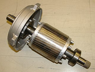
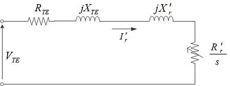
A squirrel-cage rotor is the rotating part of the common squirrel-cage induction motor. It consists of a cylinder of steel laminations, with aluminum or copper conductors embedded in its surface. In operation, the non-rotating stator winding is connected to an alternating current power source; the alternating current in the stator produces a rotating magnetic field. The rotor winding has current induced in it by the stator field, like a transformer except that the current in the rotor is varying at the stator field rotation rate minus the physical rotation rate. The interaction of the magnetic fields in the stator and the currents in the rotor produce a torque on the rotor.

<span class="mw-page-title-main">Shaded-pole motor</span> Type of AC single-phase induction motor

The shaded-pole motor is the original type of AC single-phase motor, dating back to at least as early as 1890. A shaded-pole motor is a small motor with either two or four poles, in which the auxiliary winding is composed of a copper ring or bar surrounding a portion of each pole to produce a weakly rotating magnetic field. When single phase AC supply is applied to the stator winding, due to shading provided to the poles, a rotating magnetic field is generated. This auxiliary single-turn winding is called a shading coil. Currents induced in this coil by the magnetic field create a second electrical phase by delaying the phase of magnetic flux change for that pole enough to provide a 2-phase rotating magnetic field. The direction of rotation is from the unshaded side to the shaded (ring) side of the pole. Since the phase angle between the shaded and unshaded sections is small, shaded-pole motors produce only a small starting torque relative to torque at full speed. Shaded-pole motors of the asymmetrical type shown are only reversible by disassembly and flipping over the stator, though some similar looking motors have small, switch-shortable auxiliary windings of thin wire instead of thick copper bars and can reverse electrically. Another method of electrical reversing involves four coils.

<span class="mw-page-title-main">Rotary phase converter</span> Electrical machine

A rotary phase converter, abbreviated RPC, is an electrical machine that converts power from one polyphase system to another, converting through rotary motion. Typically, single-phase electric power is used to produce three-phase electric power locally to run three-phase loads in premises where only single-phase is available.

<span class="mw-page-title-main">Repulsion motor</span> Type of AC electric motor

A repulsion motor is a type of electric motor which runs on alternating current (AC). It was formerly used as a traction motor for electric trains but has been superseded by other types of motors. Repulsion motors are classified as single phase motors.

<span class="mw-page-title-main">Reluctance motor</span> Type of electric motor

A reluctance motor is a type of electric motor that induces non-permanent magnetic poles on the ferromagnetic rotor. The rotor does not have any windings. It generates torque through magnetic reluctance.

<span class="mw-page-title-main">AC motor</span> Electric motor driven by an AC electrical input

An AC motor is an electric motor driven by an alternating current (AC). The AC motor commonly consists of two basic parts, an outside stator having coils supplied with alternating current to produce a rotating magnetic field, and an inside rotor attached to the output shaft producing a second rotating magnetic field. The rotor magnetic field may be produced by permanent magnets, reluctance saliency, or DC or AC electrical windings.

An induction generator or asynchronous generator is a type of alternating current (AC) electrical generator that uses the principles of induction motors to produce electric power. Induction generators operate by mechanically turning their rotors faster than synchronous speed. A regular AC induction motor usually can be used as a generator, without any internal modifications. Because they can recover energy with relatively simple controls, induction generators are useful in applications such as mini hydro power plants, wind turbines, or in reducing high-pressure gas streams to lower pressure.

<span class="mw-page-title-main">Rotor (electric)</span> Non-stationary part of a rotary electric motor

The rotor is a moving component of an electromagnetic system in the electric motor, electric generator, or alternator. Its rotation is due to the interaction between the windings and magnetic fields which produces a torque around the rotor's axis.

In electrical engineering, electric machine is a general term for machines using electromagnetic forces, such as electric motors, electric generators, and others. They are electromechanical energy converters: an electric motor converts electricity to mechanical power while an electric generator converts mechanical power to electricity. The moving parts in a machine can be rotating or linear. While transformers are occasionally called "static electric machines", since they do not have moving parts, generally they are not considered "machines", but as electrical devices "closely related" to the electrical machines.

Vector control, also called field-oriented control (FOC), is a variable-frequency drive (VFD) control method in which the stator currents of a three-phase AC or brushless DC electric motor are identified as two orthogonal components that can be visualized with a vector. One component defines the magnetic flux of the motor, the other the torque. The control system of the drive calculates the corresponding current component references from the flux and torque references given by the drive's speed control. Typically proportional-integral (PI) controllers are used to keep the measured current components at their reference values. The pulse-width modulation of the variable-frequency drive defines the transistor switching according to the stator voltage references that are the output of the PI current controllers.

<span class="mw-page-title-main">Switched reluctance motor</span> Externally controlled electric motor that runs by reluctance torque

The switched reluctance motor (SRM) is an electric motor that runs by reluctance torque and thus is a subgroup in reluctance motors. Unlike common brushed DC motor types, power is delivered to windings in the stator (case) rather than the rotor. This greatly simplifies mechanical design as power does not have to be delivered to a moving part which eliminates the need for a commutator, but it complicates the electrical design as some sort of switching system needs to be used to deliver power to the different windings. Electronic devices can precisely time the switching of currents, facilitating SRM configurations. Its main drawback is torque ripple. Controller technology that limits torque ripple at low speeds has been demonstrated. Sources disagree on whether it is a type of stepper motor.

A permanent magnet synchronous generator is a generator where the excitation field is provided by a permanent magnet instead of a coil. The term synchronous refers here to the fact that the rotor and magnetic field rotate with the same speed, because the magnetic field is generated through a shaft mounted permanent magnet mechanism and current is induced into the stationary armature.

<span class="mw-page-title-main">Induction regulator</span>

An induction regulator is an alternating current electrical machine, somewhat similar to an induction motor, which can provide a continuously variable output voltage. The induction regulator was an early device used to control the voltage of electric networks. Since the 1930s it has been replaced in distribution network applications by the tap transformer. Its usage is now mostly confined to electrical laboratories, electrochemical processes and arc welding. With minor variations, its setup can be used as a phase-shifting power transformer.

<span class="mw-page-title-main">Circle diagram</span>

The circle diagram is the graphical representation of the performance of the electrical machine drawn in terms of the locus of the machine's input voltage and current. It was first conceived by Alexander Heyland in 1894 and Bernhard Arthur Behrend in 1895. A newer variant devised by Johann Ossanna in 1899 is often named Ossanna diagram, Ossanna circle, Heyland-Ossanna diagram or Heyland-Ossanna circle. In 1910, Josef Sumec further improved the diagram by also incorporating the rotor resistance, then called Sumec diagram or Sumec circle.

References

  1. IEC 60050 (Publication date: 1990-10). Section 411-31: Rotation Machinery – General, IEV ref. 411-31-10: "Induction Machine – an asynchronous machine of which only one winding is energized".
  2. 1 2 Babbage, C.; Herschel, J. F. W. (January 1825). "Account of the Repetition of M. Arago's Experiments on the Magnetism Manifested by Various Substances during the Act of Rotation". Philosophical Transactions of the Royal Society. 115: 467–496. Bibcode:1825RSPT..115..467B. doi: 10.1098/rstl.1825.0023 . Retrieved 2 December 2012.
  3. Thompson, Silvanus Phillips (1895). Polyphase Electric Currents and Alternate-Current Motors (1st ed.). London: E. & F.N. Spon. p. 261. Retrieved 2 December 2012.
  4. Baily, Walter (28 June 1879). "A Mode of producing Arago's Rotation". Philosophical Magazine. 3 (1). Taylor & Francis: 115–120. Bibcode:1879PPSL....3..115B. doi:10.1088/1478-7814/3/1/318.
  5. 1 2 Vučković, Vladan (November 2006). "Interpretation of a Discovery" (PDF). The Serbian Journal of Electrical Engineers. 3 (2). Retrieved 10 February 2013.
  6. The Electrical engineer, Volume 5. (February 1890)
  7. The Electrician, Volume 50. 1923
  8. Official gazette of the United States Patent Office: Volume 50. (1890)
  9. Eugenii Katz. "Blathy". People.clarkson.edu. Archived from the original on 25 June 2008. Retrieved 4 August 2009.
  10. Ricks, G.W.D. (March 1896). "Electricity Supply Meters". Journal of the Institution of Electrical Engineers. 25 (120): 57–77. doi:10.1049/jiee-1.1896.0005.
  11. Ferraris, G. (1888). "Atti della Reale Academia delle Science di Torino". Atti della R. Academia delle Science di Torino. XXIII: 360–375.
  12. 1 2 3 4 5 6 7 Alger, P.L.; Arnold, R.E. (1976). "The History of Induction Motors in America". Proceedings of the IEEE. 64 (9): 1380–1383. doi:10.1109/PROC.1976.10329. S2CID   42191157.
  13. Froehlich, Fritz E.; Kent, Allen, eds. (1992). The Froehlich/Kent Encyclopedia of Telecommunications: Volume 17 – Television Technology to Wire Antennas (First ed.). New York: Marcel Dekker, Inc. p. 36. ISBN   978-0-8247-2902-8.
  14. The Electrical Engineer (21 September 1888). . . . a new application of the alternating current in the production of rotary motion was made known almost simultaneously by two experimenters, Nikola Tesla and Galileo Ferraris, and the subject has attracted general attention from the fact that no commutator or connection of any kind with the armature was required. . . . Vol. II. London: Charles & Co. p. 239.
  15. Ferraris, Galileo (1885). "Electromagnetic Rotation with an Alternating Current". Electrician. 36: 360–375.
  16. Tesla, Nikola; AIEE Trans. (1888). "A New System for Alternating Current Motors and Transformers". AIEE. 5: 308–324. Retrieved 17 December 2012.
  17. Jonnes, Jill (19 August 2003). Empires of Light: Edison, Tesla, Westinghouse, and the Race to Electrify the World. Random House Publishing Group. ISBN   9781588360007 via Google Books.
  18. "Electrical World". McGraw-Hill. 18 May 1921 via Google Books.
  19. Klooster, John W. (30 July 2009). Icons of Invention the Makers of the Modern World from Gutenberg to Gates. Santa Barbara: ABC-CLIO. p. 305. ISBN   978-0-313-34744-3 . Retrieved 10 September 2012.
  20. Day, Lance (1996). McNeil, Ian (ed.). Biographical Dictionary of the History of Technology. London: Routledge. p. 1204. ISBN   978-0-203-02829-2 . Retrieved 2 December 2012.
  21. Hubbell, M.W. (2011). The Fundamentals of Nuclear Power Generation Questions & Answers. Authorhouse. p. 27. ISBN   978-1463424411.
  22. VDE Committee History of Electrical Engineering IEEE German Chapter (January 2012). "150th Birthday of Michael von Dolivo-Dobrowolsky Colloquium". History of Energy Technology News. 13. Archived from the original on 25 February 2013. Retrieved 10 February 2013.
  23. Dolivo-Dobrowolsky, M. (1891). ETZ. 12: 149, 161.{{cite journal}}: Missing or empty |title= (help)
  24. Kennelly, Arthur E. (January 1893). "Impedance". Transactions of the American Institute of Electrical Engineers. X: 172–232. doi:10.1109/T-AIEE.1893.4768008. S2CID   264022523.
  25. Steinmetz, Charles Proteus (1897). "The Alternating Current Induction Motor". AIEE Trans. XIV (1): 183–217. doi:10.1109/T-AIEE.1897.5570186. S2CID   51652760.
  26. Banihaschemi, Abdolmajid (1973). Determination of the Losses in Induction Machines Due to Harmonics (PDF). Fredericton, N.B.: University of New Brunswick. pp. 1, 5–8. Archived from the original (PDF) on 4 July 2013.
  27. Steinmetz, Charles Proteus; Berg, Ernst J. (1897). Theory and Calculation of Alternating Current Phenomena. McGraw Publishing Company. OL   7218906M.
  28. 1 2 3 Alger, Philip L.; et al. (3 September 2012). "'Induction Machines' sub-section of Sec. 7 – Alternating-Current Generators and Motors". In Beaty, H. Wayne; Fink, Donald G. (eds.). Standard Handbook for Electrical Engineers Sixteenth Edition (16 ed.). McGraw Hill Professional. ISBN   978-0-07-176231-1.
  29. "AC Motors". NSW HSC Online – Charles Sturt University. Archived from the original on 30 October 2012. Retrieved 2 December 2012.
  30. 1 2 3 NEMA MG-1 2007 Condensed (2008). Information Guide for General Purpose Industrial AC Small and Medium Squirrel-Cage Induction Motor Standards. Rosslyn, Virginia US: NEMA. p. 29 (Table 11). Retrieved 2 December 2012.{{cite book}}: CS1 maint: numeric names: authors list (link)
  31. "Induction (Asynchronous) Motors" (PDF). Mississippi State University Dept of Electrical and Computer Engineering, Course ECE 3183, 'Electrical Engineering Systems for non-ECE majors'. Archived from the original (PDF) on 15 May 2016. Retrieved 2 December 2012.
  32. "Induction Motors". electricmotors.machinedesign.com. Penton Media, Inc. Archived from the original on 16 November 2007. Retrieved 12 April 2016.
  33. "Motor Formulas". elec-toolbox.com. Archived from the original on 8 May 1999. Retrieved 1 January 2013.
  34. Srivastava, Avinash; Kumar, Ravi. "Torque Slip Characteristics of Induction Motor". Course Notes. Malnad College Of Engineering.
  35. NEMA Standards Publication (2007). Application Guide for AC Adjustable Speed Drive Systems. Rosslyn, Virginia US: NEMA. p. 6. Archived from the original on 28 April 2008. Retrieved 2 December 2012.
  36. Herman, Stephen L. (2011). Alternating Current Fundamentals (8th ed.). US: Cengage Learning. pp. 529–536. ISBN   978-1-111-03913-4.
  37. 1 2 3 Peltola, Mauri. "AC Induction Motor Slip". Plantservices.com. Retrieved 18 December 2012.
  38. Keljik, Jeffrey (2009). "Chapter 12 – The Three-Phase, Squirrel-Cage Induction Motor". Electricity 4 : AC/DC Motors, Controls, and Maintenance (9th ed.). Clifton Park, NY: Delmar, Cengage Learning. pp. 112–115. ISBN   978-1-4354-0031-3.
  39. 1 2 3 Liang, Xiaodong; Ilochonwu, Obinna (January 2011). "Induction Motor Starting in Practical Industrial Applications". IEEE Transactions on Industry Applications. 47 (1): 271–280. doi:10.1109/TIA.2010.2090848. S2CID   18982431.
  40. Jamil Asghar, M.S. (2003). "Speed control of wound rotor induction motors by AC regulator based optimum voltage control". The Fifth International Conference on Power Electronics and Drive Systems, 2003. PEDS 2003. Vol. 2. pp. 1037–1040. doi:10.1109/PEDS.2003.1283113. ISBN   978-0-7803-7885-8. S2CID   113603428.
  41. Gumerov, Marina B.; Natalya L. Babikova, Marina B.; Rustam I. Gareev, Marina B. (22–25 October 2019). The cascade synchronous–asynchronous motor. Proceedings, ICOECS : 2019 International Conference on Electrotechnical Complexes and Systems. Piscataway, New Jersey: Ufa State Aviation Technical University, Ufa, Russia. p. 1. doi:10.1109/ICOECS46375.2019.8949946. ISBN   978-1-7281-1728-7.
  42. Lendenmann, Heinz; Moghadam, Reza R.; Tami, Ari; Thand, Lars-Erik. "Motoring Ahead" (PDF). Retrieved 18 April 2012.
  43. "Three phase induction motor working principle".
  44. ABB Group (Baldor Electric Company) (2016). "SPECIFIER GUIDE" (PDF). p. 6. Archived from the original (PDF) on 23 November 2016. Retrieved 4 October 2016.
  45. Fink, D.G.; Beaty, H.W. (1978). Standard Handbook for Electrical Engineers (11th ed.). McGraw-Hill. pp. 20–28 thru 20–29.
  46. 1 2 Jordan, Howard E. (1994). Energy-Efficient Electric Motors and their Applications (2nd ed.). New York: Plenum Press. ISBN   978-0-306-44698-6.
  47. 1 2 NEMA MG-1, p. 19
  48. U.S. DOE (2008). "Improving Motor and Drive System Performance: A Sourcebook for Industry" (PDF). p. 27. Retrieved 31 December 2012.
  49. de Swardt, Henk (February 2014). "Can a high efficiency MV motor be repaired?". 2014 IEEE International Conference on Industrial Technology (ICIT). Busan, South Korea: IEEE. pp. 169–174. doi:10.1109/ICIT.2014.6894933. ISBN   978-1-4799-3939-8.
  50. de Swardt, Henk (February 2014). "Electric motor efficiency myths: Work vs. Waste". 2014 IEEE International Conference on Industrial Technology (ICIT). pp. 193–196. doi:10.1109/ICIT.2014.6894937. ISBN   978-1-4799-3939-8.
  51. Hubert, Charles I. (2002). Electric Machines : Theory, Operation, Applications, Adjustment, and Control (2nd ed.). Upper Saddle River, N.J.: Prentice Hall. pp. Chapter 4. ISBN   978-0130612106.
  52. Beaty, H. Wayne, ed. (2006). "Section 5 – Three-Phase Induction Motors by Hashem Oraee" (PDF). Handbook of Electric Power Calculations (3rd ed.). New York: McGraw-Hill. ISBN   0-07-136298-3. Archived from the original (PDF) on 13 August 2012.
  53. Knight, Andy. "Induction Machine Equivalent Circuit Model". Hosted by University of Calgary. Retrieved 2 February 2022.
  54. 1 2 IEEE 112 (2004). IEEE Standard Test Procedure for Polyphase Induction Motors and Generators. New York, N.Y.: IEEE. ISBN   978-0-7381-3978-4.{{cite book}}: CS1 maint: numeric names: authors list (link)
  55. Alger (1949), p. 711
  56. 1 2 3 4 5 Özyurt, Ç.H. (2005). Parameter and Speed Estimation of Induction Motors from Manufacturers Data and Measurements (PDF). Middle East Technical University. pp. 33–34.
  57. Knight, Andy. "Determining Induction Machine Parameters". Hosted by University of Calgary. Retrieved 1 February 2022.
  58. Hameyer, Kay (2001). "Electrical Machine I: Basics, Design, Function, Operation" (PDF). RWTH Aachen University Institute of Electrical Machines. Archived from the original (PDF) on 10 February 2013. Retrieved 11 January 2013.page=133
  59. Bulletin of the Atomic Scientists. Educational Foundation for Atomic Science. 6 June 1973. Retrieved 8 August 2012.

Classical sources