Switched reluctance motor

Last updated

Switched Reluctance Motor with magnetic flux lines. Switched Reluctance motor rotation animation.gif
Switched Reluctance Motor with magnetic flux lines.

The switched reluctance motor (SRM) is a type of reluctance motor. Unlike brushed DC motor s, power is delivered to windings in the stator (case) rather than the rotor. This simplifies mechanical design because power does not have to be delivered to the moving rotor, which eliminates the need for a commutator. However it complicates the electrical design, because a switching system must deliver power to the different windings and limit torque ripple. [1] [2] Sources disagree on whether it is a type of stepper motor. [3]

Contents

The simplest SRM has the lowest construction cost of any electric motor. Industrial motors may have some cost reduction due to the lack of rotor windings or permanent magnets. Common uses include applications where the rotor must remain stationary for long periods, and in potentially explosive environments such as mining, because no commutation is involved.

The windings in an SRM are electrically isolated from each other, producing higher fault tolerance than induction motors. The optimal drive waveform is not a pure sinusoid, due to the non-linear torque relative to rotor displacement, and the windings' highly position-dependent inductance.

History

The first patent was by W. H. Taylor in 1838 in the United States. [4]

The principles for SR drives were described around 1970, [5] and enhanced by Peter Lawrenson and others from 1980 onwards. [6] At the time, some experts viewed the technology as unfeasible, [7] and practical application has been limited, partly because of control issues and unsuitable applications, and because low production numbers result in higher cost. [8] [1] [9]

Operating principle

The SRM has wound field coils as in a DC motor for the stator windings. The rotor however has no magnets or coils attached. It is a solid salient-pole rotor (having projecting magnetic poles) made of soft magnetic material (often laminated steel). When power is applied to the stator windings, the rotor's magnetic reluctance creates a force that attempts to align the rotor pole with the nearest stator pole. In order to maintain rotation, an electronic control system switches on the windings of successive stator poles in sequence so that the magnetic field of the stator "leads" the rotor pole, pulling it forward. Rather than using a mechanical commutator to switch the winding current as in traditional motors, the switched-reluctance motor uses an electronic position sensor to determine the angle of the rotor shaft and solid state electronics to switch the stator windings, which enables dynamic control of pulse timing and shaping. This differs from the apparently similar induction motor that also energizes windings in a rotating phased sequence. In an SRM the rotor magnetization is static (a salient 'North' pole remains so as the motor rotates) while an induction motor has slip (rotates at slightly less than synchronous speed). SRM's absence of slip makes it possible to know the rotor position exactly, allowing the motor to be stepped arbitrarily slowly.

Simple switching

If the poles A0 and A1 are energised then the rotor will align itself with these poles. Once this has occurred it is possible for the stator poles to be de-energised before the stator poles of B0 and B1 are energized. The rotor is now positioned at the stator poles b. This sequence continues through c before arriving back at the start. This sequence can also be reversed to achieve motion in the opposite direction. High loads and/or high de/acceleration can destabilize this sequence, causing a step to be missed, such that the rotor jumps to wrong angle, perhaps going back one step instead of forward three.

SRM simple sequence.svg

Quadrature

A much more stable system can be found by using a "quadrature" sequence in which up to two coils are energised at any time. First, stator poles A0 and A1 are energized. Then stator poles B0 and B1 are energized which, pulls the rotor so that it is aligned in between A and B. Following this A's stator poles are de-energized and the rotor continues on to be aligned with B. The sequence continues through BC, C and CA to complete a full rotation. This sequence can be reversed to achieve motion in the opposite direction. More steps between positions with identical magnetisation, so the onset of missed steps occurs at higher speeds or loads.

SRM final sequence.svg

In addition to more stable operation, this approach leads to a duty cycle of each phase of 1/2, rather than 1/3 as in the simpler sequence.

Control

The control system is responsible for giving the required sequential pulses to the power circuitry. It is possible to do this using electro-mechanical means such as commutators or analog or digital timing circuits.

Many controllers incorporate programmable logic controllers (PLCs) rather than electromechanical components. A microcontroller can enable precise phase activation timing. It also enables a soft start function in software form, in order to reduce the amount of required hardware. A feedback loop enhances the control system. [1]

Power circuitry

Asymmetric bridge converter Asymmetric Bridge Converter.svg
Asymmetric bridge converter

The most common approach to powering an SRM is to use an asymmetric bridge converter. The switching frequency can be 10 times lower than for AC motors. [3]

The phases in an asymmetric bridge converter correspond to the motor phases. If both of the power switches on either side of the phase are turned on, then that corresponding phase is actuated. Once the current has risen above the set value, the switch turns off. The energy now stored within the winding maintains the current in the same direction, the so-called back EMF (BEMF). This BEMF is fed back through the diodes to the capacitor for re-use, thus improving efficiency. [10]

N+1 pMOS switch and diodes. N+1 switch and diode.svg
N+1 pMOS switch and diodes.

This basic circuitry may be altered so that fewer components are required although the circuit performs the same action. This efficient circuit is known as the (n+1) switch and diode configuration.

A capacitor, in either configuration, is used for storing BEMF for re-use and to suppress electrical and acoustic noise by limiting fluctuations in the supply voltage.

If a phase is disconnected, an SR motor may continue to operate at lower torque, unlike an AC induction motor which turns off. [5] [11]

Applications

SRMs are used in some appliances, [12] specially in its linear form for wave energy conversion, [13] magnetic levitation trains [14] or industrial sewing machines. [15]

The same electromechanical design can be used in a generator. The load is switched to the coils in sequence to synchronize the current flow with the rotation. Such generators can be run at much higher speeds than conventional types as the armature can be made as one piece of magnetisable material, as a slotted cylinder. [16] In this case the abbreviation SRM is extended to mean Switched Reluctance Machine, (along with SRG, Switched Reluctance Generator). A topology that is both motor and generator is useful for starting the prime mover, as it saves a dedicated starter motor.

Related Research Articles

<span class="mw-page-title-main">Electric motor</span> Machine that converts electrical energy into mechanical energy

An electric motor is an electrical machine that converts electrical energy into mechanical energy. Most electric motors operate through the interaction between the motor's magnetic field and electric current in a wire winding to generate force in the form of torque applied on the motor's shaft. An electric generator is mechanically identical to an electric motor, but operates in reverse, converting mechanical energy into electrical energy.

<span class="mw-page-title-main">Stepper motor</span> Electric motor for discrete partial rotations

A stepper motor, also known as step motor or stepping motor, is an electrical motor that rotates in a series of small angular steps, instead of continuously. Stepper motors are a type of digital actuator. Like other electromagnetic actuators, they convert electric energy into mechanical position can be commanded to move and hold at one of these steps without any position sensor for feedback, as long as the motor is correctly sized to the application in respect to torque and speed.

<span class="mw-page-title-main">Commutator (electric)</span> Device for changing direction of current

A commutator is a rotary electrical switch in certain types of electric motors and electrical generators that periodically reverses the current direction between the rotor and the external circuit. It consists of a cylinder composed of multiple metal contact segments on the rotating armature of the machine. Two or more electrical contacts called "brushes" made of a soft conductive material like carbon press against the commutator, making sliding contact with successive segments of the commutator as it rotates. The windings on the armature are connected to the commutator segments.

<span class="mw-page-title-main">Alternator</span> Device converting mechanical into electrical energy

An alternator is an electrical generator that converts mechanical energy to electrical energy in the form of alternating current. For reasons of cost and simplicity, most alternators use a rotating magnetic field with a stationary armature. Occasionally, a linear alternator or a rotating armature with a stationary magnetic field is used. In principle, any AC electrical generator can be called an alternator, but usually the term refers to small rotating machines driven by automotive and other internal combustion engines.

<span class="mw-page-title-main">Stator</span> Stationary part of a system

The stator is the stationary part of a rotary system, found in electric generators, electric motors, sirens, mud motors, or biological rotors. Energy flows through a stator to or from the rotating component of the system, the rotor. In an electric motor, the stator provides a magnetic field that drives the rotating armature; in a generator, the stator converts the rotating magnetic field to electric current. In fluid powered devices, the stator guides the flow of fluid to or from the rotating part of the system.

<span class="mw-page-title-main">Induction motor</span> Type of AC electric motor

An induction motor or asynchronous motor is an AC electric motor in which the electric current in the rotor that produces torque is obtained by electromagnetic induction from the magnetic field of the stator winding. An induction motor therefore needs no electrical connections to the rotor. An induction motor's rotor can be either wound type or squirrel-cage type.

<span class="mw-page-title-main">Synchronous motor</span> Type of AC motor

A synchronous electric motor is an AC electric motor in which, at steady state, the rotation of the shaft is synchronized with the frequency of the supply current; the rotation period is exactly equal to an integer number of AC cycles. Synchronous motors use electromagnets as the stator of the motor which create a magnetic field that rotates in time with the oscillations of the current. The rotor with permanent magnets or electromagnets turns in step with the stator field at the same rate and as a result, provides the second synchronized rotating magnet field. A synchronous motor is termed doubly fed if it is supplied with independently excited multiphase AC electromagnets on both the rotor and stator.

<span class="mw-page-title-main">Brushless DC electric motor</span> Synchronous electric motor powered by an electronic controller

A brushless DC electric motor (BLDC), also known as an electronically commutated motor, is a synchronous motor using a direct current (DC) electric power supply. It uses an electronic controller to switch DC currents to the motor windings producing magnetic fields that effectively rotate in space and which the permanent magnet rotor follows. The controller adjusts the phase and amplitude of the current pulses that control the speed and torque of the motor. It is an improvement on the mechanical commutator (brushes) used in many conventional electric motors.

<span class="mw-page-title-main">DC motor</span> Motor which works on direct current

A DC motor is an electrical motor that uses direct current (DC) to produce mechanical force. The most common types rely on magnetic forces produced by currents in the coils. Nearly all types of DC motors have some internal mechanism, either electromechanical or electronic, to periodically change the direction of current in part of the motor.

<span class="mw-page-title-main">Rotary converter</span> Electrical machine

A rotary converter is a type of electrical machine which acts as a mechanical rectifier, inverter or frequency converter.

<span class="mw-page-title-main">Armature (electrical)</span> Power-producing component of an electric machine

In electrical engineering, the armature is the winding of an electric machine which carries alternating current. The armature windings conduct AC even on DC machines, due to the commutator action or due to electronic commutation, as in brushless DC motors. The armature can be on either the rotor or the stator, depending on the type of electric machine.

<span class="mw-page-title-main">Field coil</span> Electromagnet used to generate a magnetic field in an electro-magnetic machine

A field coil is an electromagnet used to generate a magnetic field in an electro-magnetic machine, typically a rotating electrical machine such as a motor or generator. It consists of a coil of wire through which a current flows.

<span class="mw-page-title-main">Repulsion motor</span> Type of AC electric motor

A repulsion motor is a type of electric motor which runs on alternating current (AC). It was formerly used as a traction motor for electric trains but has been superseded by other types of motors. Repulsion motors are classified as single phase motors.

<span class="mw-page-title-main">Reluctance motor</span> Type of electric motor

A reluctance motor is a type of electric motor that induces non-permanent magnetic poles on the ferromagnetic rotor. The rotor does not have any windings. It generates torque through magnetic reluctance.

<span class="mw-page-title-main">AC motor</span> Electric motor driven by an AC electrical input

An AC motor is an electric motor driven by an alternating current (AC). The AC motor commonly consists of two basic parts, an outside stator having coils supplied with alternating current to produce a rotating magnetic field, and an inside rotor attached to the output shaft producing a second rotating magnetic field. The rotor magnetic field may be produced by permanent magnets, reluctance saliency, or DC or AC electrical windings.

An induction generator or asynchronous generator is a type of alternating current (AC) electrical generator that uses the principles of induction motors to produce electric power. Induction generators operate by mechanically turning their rotors faster than synchronous speed. A regular AC induction motor usually can be used as a generator, without any internal modifications. Because they can recover energy with relatively simple controls, induction generators are useful in applications such as mini hydro power plants, wind turbines, or in reducing high-pressure gas streams to lower pressure.

<span class="mw-page-title-main">Rotor (electric)</span> Non-stationary part of a rotary electric motor

The rotor is a moving component of an electromagnetic system in the electric motor, electric generator, or alternator. Its rotation is due to the interaction between the windings and magnetic fields which produces a torque around the rotor's axis.

A brushed DC electric motor is an internally commutated electric motor designed to be run from a direct current power source and utilizing an electric brush for contact.

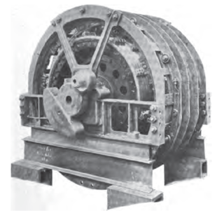
In electrical engineering, electric machine is a general term for machines using electromagnetic forces, such as electric motors, electric generators, and others. They are electromechanical energy converters: an electric motor converts electricity to mechanical power while an electric generator converts mechanical power to electricity. The moving parts in a machine can be rotating or linear. While transformers are occasionally called "static electric machines", since they do not have moving parts, generally they are not considered "machines", but as electrical devices "closely related" to the electrical machines.

<span class="mw-page-title-main">Switched reluctance linear motor</span> Switched Reluctance linear motor

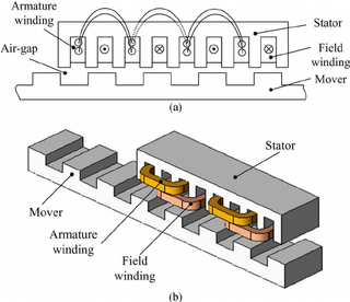
Switched reluctance linear motors (SRLMs) are a type of electric machines called linear motors which work based on the principle of a varying magnetic reluctance for force generation. The system can be used in reversed mode and then is called Switched Reluctance Linear Generator. The SRLMs consist of two parts: the active part or primary part and the passive or secondary. The active part contains the windings and defines two main types of LSRMs: transverse and longitudinal. It is longitudinal when the plane that contains the flux lines is parallel to the line of movement and transverse when it is perpendicular. Other classifications are considering the windings totally concentrated in one coil per phase or partially concentrated in two poles per phase or four poles per phase (double-sided). Switched Reluctance motors have been used extensively in clocks and phonograph turntables before, but nowadays, with the rising emphasis on energy efficiency, SR motors are taking more prominent roles in appliances, industrial uses, and commercial and vehicular applications and they are getting traction in the linear applications due to their simplicity, robustness, economic rationality, and high fault tolerance ability as compared with the Linear Synchronous and Linear Induction motors. The SRLM has been researched widely and there are applications of SRLMs and generators for example in wave energy conversion or hyperloop ultra high speed transportation system. One of the main advantages of the SRLM is that it does not require the use of permanent magnets, which are considered a scarce material, so it enables it to be deployed over long distances.

References

  1. 1 2 3 Bartos, Frank (1 February 2003). "Springtime for Switched-Reluctance Motors?". Control Engineering. Archived from the original on 19 May 2020. Digital signal processors and special algorithms in SR controls are vital to precisely time current pulses fed to the motor windings relative to rotor and stator position . SR technology has not experienced real breakthroughs . reduced interest in SR technology
  2. Stankovic, A.M.; Tadmor, G.; Coric, Coric (6–10 October 1996). Low torque ripple control of current-fed switched reluctance motors. IAS '96. Conference Record of the 1996 IEEE Industry Applications Conference Thirty-First IAS Annual Meeting. San Diego, Cal. S2CID   61325620 . Retrieved 3 June 2024.
  3. 1 2 Bartos, Frank (1 March 2010). "Resurgence for SR Motors, Drives?". Control Engineering. Archived from the original on 19 May 2020. SR drives operate at switching frequencies typically 10 times lower than comparable ac drives . Some other sources seem to put both motors in the same category. Emotron concurs that today's SR motor is not a stepping motor since current is continuously monitored and controlled relative to rotor angular position
  4. "Charged EVs | A closer look at switched reluctance motors". chargedevs.com. 25 January 2013. Retrieved 25 July 2020.
  5. 1 2 Bartos, Frank (10 March 2010). "SR motor anatomy: See inside switched reluctance motors". Control Engineering. Archived from the original on 27 October 2018.
  6. "Variable-speed switched reluctance motors", P.J. Lawrenson, J.M. Stephenson, P.T. Blenkinsop, J. Corda and N.N. Fulton, IEE Proceedings B - Electric Power Applications, Volume 127, Issue 4, 1980. pp. 253-265
  7. "IEEE Edison Medal Recipients". www.ieee.org. Archived from the original on 19 May 2020.
  8. Bartos, Frank (1 November 1999). "'Forward to the Past' with SR Technology". Control Engineering. Archived from the original on 19 May 2020.
  9. Bartos, Frank (30 May 2003). "Switched-Reluctance Motors and Controls Offer an Alternative Solution". Control Engineering. Archived from the original on 19 May 2020. Because of their relatively smaller production numbers, manufacturing costs for SR technology tend to be higher
  10. "Power Semiconductor Switching Circuits for SRM(Power Controllers)". When the phase winding is to be disconnected from the supply (this instant is also dependent on the position of the shaft) the devices T1 and T2 are turned off .The stored energy in the phase winding A tends to maintain the current in the same direction. This current passes from the winding through D1 and D2 to the supply. Thus the stored energy is fed back to the mains.
  11. "Fault Tolerant Switched Reluctance Machine's Comparative Analysis | Fault Tolerance | Reliability Engineering". Scribd.
  12. Bush, Steve (2009). "Dyson vacuums 104,000 rpm brushless DC technology". Electronics Weekly Magazine. Archived from the original on 11 April 2012.{{cite web}}: CS1 maint: numeric names: authors list (link)
  13. "Wedge Global | Líder en energia de las olas" . Retrieved 12 June 2023.
  14. "La USEP participa en el proyecto SCALE para desarrollar el sistema de aceleración para el transporte ultrarrápido Hyperloop" (in Spanish). 20 February 2023. Archived from the original on 13 June 2023. Retrieved 29 July 2023.
  15. Laithwaite, Eric R. (1987), Laithwaite, Eric R. (ed.), "The contributions of the textile men", A History of Linear Electric Motors, London: Macmillan Education UK, pp. 52–83, doi:10.1007/978-1-349-08296-4_3, ISBN   978-1-349-08296-4 , retrieved 12 June 2023
  16. "Switched Reluctance Generators and Their Control". Archived from the original on 29 November 2014. Retrieved 18 November 2016.{{cite web}}: CS1 maint: bot: original URL status unknown (link)