Alternator

Last updated

Alternators made in 1909 by Ganz Works in the power generating hall of a Russian hydroelectric station (photograph by Prokudin-Gorsky, 1911). Gorskii 04414u.jpg
Alternators made in 1909 by Ganz Works in the power generating hall of a Russian hydroelectric station (photograph by Prokudin-Gorsky, 1911).

An alternator is an electrical generator that converts mechanical energy to electrical energy in the form of alternating current. [2] For reasons of cost and simplicity, most alternators use a rotating magnetic field with a stationary armature. [3] Occasionally, a linear alternator or a rotating armature with a stationary magnetic field is used. In principle, any AC electrical generator can be called an alternator, but usually the term refers to small rotating machines driven by automotive and other internal combustion engines.

Contents

An alternator that uses a permanent magnet for its magnetic field is called a magneto. Alternators in power stations driven by steam turbines are called turbo-alternators. Large 50 or 60 Hz three-phase alternators in power plants generate most of the world's electric power, which is distributed by electric power grids. [4]

History

In what is considered the first industrial use of alternating current in 1891, workmen pose with a Westinghouse alternator at the Ames Hydroelectric Generating Plant. This machine was used as a generator producing 3,000-volt, 133-hertz, single-phase AC, and an identical machine 3 miles (4.8 km) away was used as an AC motor. Ames Colorado generator alternating current power plant 1891 Gold King Mine.png
In what is considered the first industrial use of alternating current in 1891, workmen pose with a Westinghouse alternator at the Ames Hydroelectric Generating Plant. This machine was used as a generator producing 3,000-volt, 133-hertz, single-phase AC, and an identical machine 3 miles (4.8 km) away was used as an AC motor.

Alternating current generating systems were known in simple forms from the discovery of the magnetic induction of electric current in the 1830s. Rotating generators naturally produced alternating current but, since there was little use for it, it was normally converted into direct current via the addition of a commutator in the generator. [8] The early machines were developed by pioneers such as Michael Faraday and Hippolyte Pixii. Faraday developed the "rotating rectangle", whose operation was heteropolar – each active conductor passed successively through regions where the magnetic field was in opposite directions. [9] Lord Kelvin and Sebastian Ferranti also developed early alternators, producing frequencies between 100 and 300 Hz.[ citation needed ]

The late 1870s saw the introduction of first large scale electrical systems with central generation stations to power Arc lamps, used to light whole streets, factory yards, or the interior of large warehouses. Some, such as Yablochkov arc lamps introduced in 1878, ran better on alternating current, and the development of these early AC generating systems was accompanied by the first use of the word "alternator". [10] [8] Supplying the proper amount of voltage from generating stations in these early systems was left up to the engineer's skill in "riding the load". [11] In 1883 the Ganz Works invented the constant voltage generator [12] that could produce a stated output voltage, regardless of the value of the actual load. [13] The introduction of transformers in the mid-1880s led to the widespread use of alternating current and the use of alternators needed to produce it. [14] After 1891, polyphase alternators were introduced to supply currents of multiple differing phases. [15] Later alternators were designed for various alternating current frequencies between sixteen and about one hundred hertz, for use with arc lighting, incandescent lighting and electric motors. [16] Specialized radio frequency alternators like the Alexanderson alternator were developed as longwave radio transmitters around World War 1 and used in a few high power wireless telegraphy stations before vacuum tube transmitters replaced them.[ citation needed ]

Principle of operation

Diagram of a simple alternator with a rotating magnetic core (rotor) and stationary wire (stator) also showing the current induced in the stator by the rotating magnetic field of the rotor. Alternator 1.svg
Diagram of a simple alternator with a rotating magnetic core (rotor) and stationary wire (stator) also showing the current induced in the stator by the rotating magnetic field of the rotor.

A conductor moving relative to a magnetic field develops an electromotive force (EMF) in it (Faraday's Law). This EMF reverses its polarity when it moves under magnetic poles of opposite polarity. Typically, a rotating magnet, called the rotor, turns within a stationary set of conductors, called the stator, wound in coils on an iron core. The field cuts across the conductors, generating an induced EMF (electromotive force), as the mechanical input causes the rotor to turn.[ citation needed ]

The rotating magnetic field induces an AC voltage in the stator windings. Since the currents in the stator windings vary in step with the position of the rotor, an alternator is a synchronous generator. [3]

The rotor's magnetic field may be produced by permanent magnets, or by a field coil electromagnet. Automotive alternators use a rotor winding which allows control of the alternator's generated voltage by varying the current in the rotor field winding. Permanent magnet machines avoid the loss due to magnetizing current in the rotor, but are restricted in size, due to the cost of the magnet material. Since the permanent magnet field is constant, the terminal voltage varies directly with the speed of the generator. Brushless AC generators are usually larger than those used in automotive applications.[ citation needed ]

An automatic voltage control device controls the field current to keep output voltage constant. If the output voltage from the stationary armature coils drops due to an increase in demand, more current is fed into the rotating field coils through the voltage regulator (VR). This increases the magnetic field around the field coils which induces a greater voltage in the armature coils. Thus, the output voltage is brought back up to its original value.[ citation needed ]

Alternators used in central power stations also control the field current to regulate reactive power and to help stabilize the power system against the effects of momentary faults. Often there are three sets of stator windings, physically offset so that the rotating magnetic field produces a three phase current, displaced by one-third of a period with respect to each other. [17]

Synchronous speeds

One cycle of alternating current is produced each time a pair of field poles passes over a point on the stationary winding. The relation between speed and frequency is , where is the frequency in Hz (cycles per second). is the number of poles (2, 4, 6, …) and is the rotational speed in revolutions per minute (r/min). Very old descriptions of alternating current systems sometimes give the frequency in terms of alternations per minute, counting each half-cycle as one alternation; so 12,000 alternations per minute corresponds to 100 Hz.[ citation needed ]

The output frequency of an alternator depends on the number of poles and the rotational speed. The speed corresponding to a particular frequency is called the synchronous speed for that frequency. This table [18] gives some examples:

PolesRotation speed (r/min), giving…
50 Hz60 Hz400 Hz
23,0003,60024,000
41,5001,80012,000
61,0001,2008,000
87509006,000
106007204,800
125006004,000
14428.6514.33,429
163754503,000
18333.34002,667
203003602,400
401501801,200

Classifications

Alternators may be classified by method of excitation, number of phases, the type of rotation, cooling method, and their application. [19]

By excitation

There are two main ways to produce the magnetic field used in the alternators, by using permanent magnets which create their own persistent magnetic field or by using field coils. The alternators that use permanent magnets are specifically called magnetos.[ citation needed ]

In other alternators, wound field coils form an electromagnet to produce the rotating magnetic field.[ citation needed ]

A device that uses permanent magnets to produce alternating current is called a permanent magnet alternator (PMA). A permanent magnet generator (PMG) may produce either alternating current, or direct current if it has a commutator.[ citation needed ]

Direct-connected direct-current (DC) generator

This method of excitation consists of a smaller direct-current (DC) generator fixed on the same shaft with the alternator. The DC generator generates a small amount of electricity just enough to excite the field coils of the connected alternator to generate electricity. A variation of this system is a type of alternator which uses direct current from a battery for initial excitation upon start-up, after which the alternator becomes self-excited. [19]

Transformation and rectification

This method depends on residual magnetism retained in the iron core to generate weak magnetic field which would allow a weak voltage to be generated. This voltage is used to excite the field coils for the alternator to generate stronger voltage as part of its build up process. After the initial AC voltage buildup, the field is supplied with rectified voltage from the alternator. [19]

Brushless alternators

A brushless alternator is composed of two alternators built end-to-end on one shaft. Until 1966, alternators used brushes with rotating field. [20] With advancement in semiconductor technology, brushless alternators are possible. Smaller brushless alternators may look like one unit but the two parts are readily identifiable on the large versions. The larger of the two sections is the main alternator and the smaller one is the exciter. The exciter has stationary field coils and a rotating armature (power coils). The main alternator uses the opposite configuration with a rotating field and stationary armature. A bridge rectifier, called the rotating rectifier assembly, is mounted on the rotor. Neither brushes nor slip rings are used, which reduces the number of wearing parts. The main alternator has a rotating field as described above and a stationary armature (power generation windings).

Varying the amount of current through the stationary exciter field coils varies the 3-phase output from the exciter. This output is rectified by a rotating rectifier assembly, mounted on the rotor, and the resultant DC supplies the rotating field of the main alternator and hence alternator output. The result of all this is that a small DC exciter current indirectly controls the output of the main alternator. [21]

By number of phases

Another way to classify alternators is by the number of phases of their output voltage. The output can be single phase, or polyphase. Three-phase alternators are the most common, but polyphase alternators can be two phase, six phase, or more. [19]

By rotating part

The revolving part of alternators can be the armature or the magnetic field. The revolving armature type has the armature wound on the rotor, where the winding moves through a stationary magnetic field. The revolving armature type is not often used. [19] The revolving field type has magnetic field on the rotor to rotate through a stationary armature winding. The advantage is that then the rotor circuit carries much less power than the armature circuit, making the slip ring connections smaller and less costly; only two contacts are needed for the direct-current rotor, whereas often a rotor winding has three phases and multiple sections which would each require a slip-ring connection. The stationary armature can be wound for any convenient medium voltage level, up to tens of thousands of volts; manufacture of slip ring connections for more than a few thousand volts is costly and inconvenient.[ citation needed ]

Cooling methods

Many alternators are cooled by ambient air, forced through the enclosure by an attached fan on the same shaft that drives the alternator. In vehicles such as transit buses, a heavy demand on the electrical system may require a large alternator to be oil-cooled. [22] In marine applications water-cooling is also used. Expensive automobiles may use water-cooled alternators to meet high electrical system demands.[ citation needed ]

Specific applications

Electric generators

Most power generation stations use synchronous machines as their generators. Connection of these generators to the utility grid requires synchronization conditions to be met. [23]

Automotive alternators

Alternator mounted on an automobile engine with a serpentine belt pulley (belt not present.) Jeep 2.5 liter 4-cylinder engine chromed e.jpg
Alternator mounted on an automobile engine with a serpentine belt pulley (belt not present.)

Alternators are used in modern internal combustion engine automobiles to charge the battery and to power the electrical system when its engine is running.[ citation needed ]

Until the 1960s, automobiles used DC dynamo generators with commutators. With the availability of affordable silicon-diode rectifiers, alternators were used instead.[ citation needed ]

Diesel-electric locomotive alternators

In later diesel-electric locomotives and diesel electric multiple units, the prime mover turns an alternator which provides electricity for the traction motors (AC or DC).[ citation needed ]

The traction alternator usually incorporates integral silicon diode rectifiers to provide the traction motors with up to 1,200 volts DC.[ citation needed ]

The first diesel electric locomotives, and many of those still in service, use DC generators as, before silicon power electronics, it was easier to control the speed of DC traction motors. Most of these had two generators: one to generate the excitation current for a larger main generator.[ citation needed ]

Optionally, the generator also supplies head-end power (HEP) or power for electric train heating. The HEP option requires a constant engine speed, typically 900 r/min for a 480 V 60 Hz HEP application, even when the locomotive is not moving.[ citation needed ]

Marine alternators

Marine alternators used in yachts are similar to automotive alternators, with appropriate adaptations to the salt-water environment. Marine alternators are designed to be explosion proof (ignition protected) so that brush sparking will not ignite explosive gas mixtures in an engine room environment. They may be 12 or 24 volt depending on the type of system installed. Larger marine diesels may have two or more alternators to cope with the heavy electrical demand of a modern yacht. On single alternator circuits, the power may be split between the engine starting battery and the domestic or house battery (or batteries) by use of a split-charge diode (battery isolator) or a voltage-sensitive relay. Due to the high cost of large house battery banks, Marine alternators generally use external regulators. Multistep regulators control the field current to maximize the charging effectiveness (time to charge) and battery life. Multistep regulators can be programmed for different battery types. Two temperature sensors can be added, one for the battery to adjust charging voltage and an over-temperature sensor on the actual alternator to protect it from overheating.[ citation needed ]

Aviation

Radio alternators

High frequency alternators of the variable-reluctance type were applied commercially to radio transmission in the low-frequency radio bands. These were used for transmission of Morse code and, experimentally, for transmission of voice and music. In the Alexanderson alternator, both the field winding and armature winding are stationary, and current is induced in the armature by virtue of the changing magnetic reluctance of the rotor (which has no windings or current carrying parts). Such machines were made to produce radio frequency current for radio transmissions, although the efficiency was low.[ citation needed ]

See also

Related Research Articles

<span class="mw-page-title-main">Electromagnetic coil</span> Electrical component

An electromagnetic coil is an electrical conductor such as a wire in the shape of a coil. Electromagnetic coils are used in electrical engineering, in applications where electric currents interact with magnetic fields, in devices such as electric motors, generators, inductors, electromagnets, transformers, and sensor coils. Either an electric current is passed through the wire of the coil to generate a magnetic field, or conversely, an external time-varying magnetic field through the interior of the coil generates an EMF (voltage) in the conductor.

<span class="mw-page-title-main">Electric motor</span> Machine that converts electrical energy into mechanical energy

An electric motor is an electrical machine that converts electrical energy into mechanical energy. Most electric motors operate through the interaction between the motor's magnetic field and electric current in a wire winding to generate force in the form of torque applied on the motor's shaft. An electric generator is mechanically identical to an electric motor, but operates in reverse, converting mechanical energy into electrical energy.

<span class="mw-page-title-main">Electric generator</span> Device that converts other energy to electrical energy

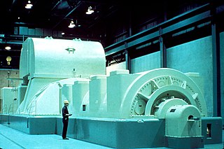
In electricity generation, a generator is a device that converts motion-based power or fuel-based power into electric power for use in an external circuit. Sources of mechanical energy include steam turbines, gas turbines, water turbines, internal combustion engines, wind turbines and even hand cranks. The first electromagnetic generator, the Faraday disk, was invented in 1831 by British scientist Michael Faraday. Generators provide nearly all the power for electrical grids.

<span class="mw-page-title-main">Stator</span> Stationary part of a system

The stator is the stationary part of a rotary system, found in electric generators, electric motors, sirens, mud motors or biological rotors, which is typically contrasted with rotor. Energy flows through a stator to or from the rotating component of the system. In an electric motor, the stator provides a magnetic field that drives the rotating armature; in a generator, the stator converts the rotating magnetic field to electric current. In fluid powered devices, the stator guides the flow of fluid to or from the rotating part of the system.

<span class="mw-page-title-main">Synchronous motor</span> Type of AC motor

A synchronous electric motor is an AC electric motor in which, at steady state, the rotation of the shaft is synchronized with the frequency of the supply current; the rotation period is exactly equal to an integer number of AC cycles. Synchronous motors use electromagnets as the stator of the motor which create a magnetic field that rotates in time with the oscillations of the current. The rotor with permanent magnets or electromagnets turns in step with the stator field at the same rate and as a result, provides the second synchronized rotating magnet field. A synchronous motor is termed doubly fed if it is supplied with independently excited multiphase AC electromagnets on both the rotor and stator.

<span class="mw-page-title-main">DC motor</span> Motor which works on direct current

A DC motor is an electrical motor that uses direct current (DC) to produce mechanical force. The most common types rely on magnetic forces produced by currents in the coils. Nearly all types of DC motors have some internal mechanism, either electromechanical or electronic, to periodically change the direction of current in part of the motor.

<span class="mw-page-title-main">Rotary converter</span> Electrical machine

A rotary converter is a type of electrical machine which acts as a mechanical rectifier, inverter or frequency converter.

<span class="mw-page-title-main">Armature (electrical)</span> Power-producing component of an electric machine

In electrical engineering, the armature is the winding of an electric machine which carries alternating current. The armature windings conduct AC even on DC machines, due to the commutator action or due to electronic commutation, as in brushless DC motors. The armature can be on either the rotor or the stator, depending on the type of electric machine.

<span class="mw-page-title-main">Field coil</span> Electromagnet used to generate a magnetic field in an electro-magnetic machine

A field coil is an electromagnet used to generate a magnetic field in an electro-magnetic machine, typically a rotating electrical machine such as a motor or generator. It consists of a coil of wire through which a current flows.

<span class="mw-page-title-main">Gramme machine</span> Electrical generator that produces direct current

A Gramme machine, Gramme ring, Gramme magneto, or Gramme dynamo is an electrical generator that produces direct current, named for its Belgian inventor, Zénobe Gramme, and was built as either a dynamo or a magneto. It was the first generator to produce power on a commercial scale for industry. Inspired by a machine invented by Antonio Pacinotti in 1860, Gramme was the developer of a new induced rotor in form of a wire-wrapped ring and demonstrated this apparatus to the Academy of Sciences in Paris in 1871. Although popular in 19th century electrical machines, the Gramme winding principle is no longer used since it makes inefficient use of the conductors. The portion of the winding on the interior of the ring cuts no flux and does not contribute to energy conversion in the machine. The winding requires twice the number of turns and twice the number of commutator bars as an equivalent drum-wound armature.

<span class="mw-page-title-main">AC motor</span> Electric motor driven by an AC electrical input

An AC motor is an electric motor driven by an alternating current (AC). The AC motor commonly consists of two basic parts, an outside stator having coils supplied with alternating current to produce a rotating magnetic field, and an inside rotor attached to the output shaft producing a second rotating magnetic field. The rotor magnetic field may be produced by permanent magnets, reluctance saliency, or DC or AC electrical windings.

An induction generator or asynchronous generator is a type of alternating current (AC) electrical generator that uses the principles of induction motors to produce electric power. Induction generators operate by mechanically turning their rotors faster than synchronous speed. A regular AC induction motor usually can be used as a generator, without any internal modifications. Because they can recover energy with relatively simple controls, induction generators are useful in applications such as mini hydro power plants, wind turbines, or in reducing high-pressure gas streams to lower pressure.

<span class="mw-page-title-main">Rotor (electric)</span> Non-stationary part of a rotary electric motor

The rotor is a moving component of an electromagnetic system in the electric motor, electric generator, or alternator. Its rotation is due to the interaction between the windings and magnetic fields which produces a torque around the rotor's axis.

<span class="mw-page-title-main">Dynamo</span> Electrical generator that produces direct current with the use of a commutator

A dynamo is an electrical generator that creates direct current using a commutator. Dynamos were the first electrical generators capable of delivering power for industry, and the foundation upon which many other later electric-power conversion devices were based, including the electric motor, the alternating-current alternator, and the rotary converter.

In electrical engineering, electric machine is a general term for machines using electromagnetic forces, such as electric motors, electric generators, and others. They are electromechanical energy converters: an electric motor converts electricity to mechanical power while an electric generator converts mechanical power to electricity. The moving parts in a machine can be rotating or linear. While transformers are occasionally called "static electric machines", since they do not have moving parts, generally they are not considered "machines", but as electrical devices "closely related" to the electrical machines.

<span class="mw-page-title-main">Excitation (magnetic)</span> Generation of a magnetic field by an electric current

In electromagnetism, excitation is the process of generating a magnetic field by means of an electric current.

A permanent magnet synchronous generator is a generator where the excitation field is provided by a permanent magnet instead of a coil. The term synchronous refers here to the fact that the rotor and magnetic field rotate with the same speed, because the magnetic field is generated through a shaft mounted permanent magnet mechanism and current is induced into the stationary armature.

<span class="mw-page-title-main">Magneto</span> Electricity-producing machine

A magneto is an electrical generator that uses permanent magnets to produce periodic pulses of alternating current. Unlike a dynamo, a magneto does not contain a commutator to produce direct current. It is categorized as a form of alternator, although it is usually considered distinct from most other alternators, which use field coils rather than permanent magnets.

<span class="mw-page-title-main">Flux switching alternator</span>

A flux switching alternator is a form of high-speed alternator, an AC electrical generator, intended for direct drive by a turbine. They are simple in design with the rotor containing no coils or magnets, making them rugged and capable of high rotation speeds. This makes them suitable for their only widespread use, in guided missiles.

<span class="mw-page-title-main">Single-phase generator</span>

Single-phase generator is an alternating current electrical generator that produces a single, continuously alternating voltage. Single-phase generators can be used to generate power in single-phase electric power systems. However, polyphase generators are generally used to deliver power in three-phase distribution system and the current is converted to single-phase near the single-phase loads instead. Therefore, single-phase generators are found in applications that are most often used when the loads being driven are relatively light, and not connected to a three-phase distribution, for instance, portable engine-generators. Larger single-phase generators are also used in special applications such as single-phase traction power for railway electrification systems.

References

  1. "Abraham Ganz at the Hindukush". Poemas del río Wang. Studiolum. Archived from the original on 11 February 2016. Retrieved 30 September 2015.
  2. Aylmer-Small, Sidney (1908). "Lesson 28: Alternators". Electrical railroading; or, Electricity as applied to railroad transportation. Chicago: Frederick J. Drake & Co. pp. 456–463.
  3. 1 2 Gordon R. Selmon, Magnetoelectric Devices, John Wiley and Sons, 1966 no ISBN pp. 391-393
  4. "List of Plug/Sockets and Voltage of Different Countries". World Standards. World Standards.
  5. D. M. Mattox, The Foundations of Vacuum Coating Technology, page 39
  6. "CHARLES C. BRITTON, An Early Electric Power Facility in Colorado" (PDF). Colorado Magazine. Vol. 49, no. 3. Summer 1972. p. 185. Archived from the original (PDF) on 28 July 2016. Retrieved 15 August 2016.
  7. "Milestones:Ames Hydroelectric Generating Plant, 1891". IEEE Global History Network. IEEE. Retrieved 29 July 2011.
  8. 1 2 Christopher Cooper, The Truth about Tesla: The Myth of the Lone Genius in the History of Innovation, Quarto Publishing Group USA – 2015, page 93
  9. Thompson, Sylvanus P., Dynamo-Electric Machinery. p. 7.
  10. Jill Jonnes, Empires of Light: Edison, Tesla, Westinghouse, And The Race To Electrify The World, Random House – 2004, page 47
  11. Donald Scott McPartland, Almost Edison: How William Sawyer and Others Lost the Race to Electrification, ProQuest – 2006, page 135
  12. American Society for Engineering Education (1995). Proceedings, Part 2. p. 1848.
  13. Robert L. Libbey (1991). A Handbook of Circuit Math for Technical Engineers. CRC Press. p. 22. ISBN   9780849374005.
  14. Thompson, Sylvanus P. "Milestones:Alternating Current Electrification, 1886". IEEE Global History Network. Retrieved 22 September 2013.
  15. Thompson, Sylvanus P., Dynamo-Electric Machinery. pp. 17
  16. Thompson, Sylvanus P., Dynamo-Electric Machinery. pp. 16
  17. B. M. Weedy. Electric Power Systems Second Edition, John Wiley and Sons, 1972, ISBN   0 471 92445 8, p. 141
  18. The Electrical Year Book 1937, published by Emmott & Co. Ltd., Manchester, England, page 72
  19. 1 2 3 4 5 Aviation Maintenance Technician Handbook—General (FAA-H-8083-30) (PDF). Federal Aviation Administration. 2008. pp. 10_160–10_161. Archived from the original (PDF) on 6 September 2013. Retrieved 6 September 2013.
  20. "Cummins Generator Technologies". stamford-avk.com. Cummins Generator Technologies. Retrieved 18 August 2022.
  21. G. K. Dubey, Fundamentals of Electrical Drives, CRC Press, 2002, ISBN   084932422X, page 350
  22. Gus Wright, Fundamentals of Medium/Heavy Duty Diesel Engines, Jones & Bartlett Publishers, 2015, ISBN   128406705X page 1233
  23. Soft synchronization of dispersed generators to micro grids for smart grid applications