Above-ground structure for bulk transfer and distribution of electricity
This article is about power lines for general transmission of electrical power. For overhead lines used to power road and rail vehicles, see Overhead line.
An overhead power line is a structure used in electric power transmission and distribution to transmit electrical energy along large distances. It consists of one or more conductors (commonly multiples of three) suspended by towers or poles. Since the surrounding air provides good cooling, insulation along long passages and allows optical inspection, overhead power lines are generally the lowest-cost method of power transmission for large quantities of electric energy.
Towers for support of the lines are made of wood (as-grown or laminated), steel or aluminum (either lattice structures or tubular poles), concrete, and occasionally reinforced plastics. The bare wire conductors on the line are generally made of aluminum (either plain or reinforced with steel, or composite materials such as carbon and glass fiber), though some copper wires are used in medium-voltage distribution and low-voltage connections to customer premises. A major goal of overhead power line design is to maintain adequate clearance between energized conductors and the ground so as to prevent dangerous contact with the line, and to provide reliable support for the conductors, resilience to storms, ice loads, earthquakes and other potential damage causes.[1] Today some overhead lines are routinely operated at voltages exceeding 765,000 volts between conductors, with even higher voltages possible in some cases.
Classification by operating voltage
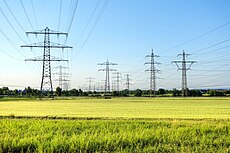
High- and medium-voltage power lines in Łomża, Poland
Overhead power transmission lines are classified in the electrical power industry by the range of voltages:
Low voltage (LV) – less than 1000 volts, used for connection between a residential or small commercial customer and the utility.
Medium voltage (MV; distribution) – between 1000 volts (1 kV) and 69 kV, used for distribution in urban and rural areas.
High voltage (HV; subtransmission less than 100kV; subtransmission or transmission at voltages such as 115kV and 138kV), used for sub-transmission and transmission of bulk quantities of electric power and connection to very large consumers.
Extra high voltage (EHV; transmission) – from 345 kV, up to about 800 kV,[2][pageneeded] used for long distance, very high power transmission.
Ultra high voltage (UHV) – higher than 800 kV. The Financial Times reported UHV lines are a "game changer", making a global electricity grid potentially feasible. StateGrid said that compared to conventional lines, UHV enables the transmission of five times more power, over six times the distance.[3]
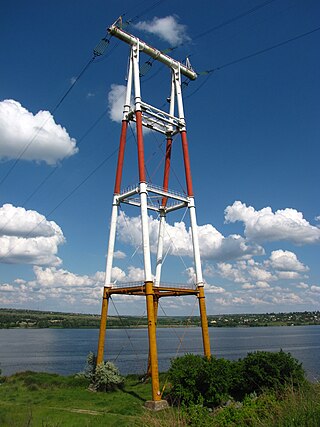
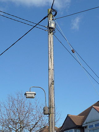
Structures for overhead lines take a variety of shapes depending on the type of line. Structures may be as simple as wood poles directly set in the earth, carrying one or more cross-arm beams to support conductors, or "armless" construction with conductors supported on insulators attached to the side of the pole. Tubular steel poles are typically used in urban areas. High-voltage lines are often carried on lattice-type steel towers or pylons. For remote areas, aluminum towers may be placed by helicopters.[4][5] Concrete poles have also been used.[1] Poles made of reinforced plastics are also available, but their high cost restricts application.
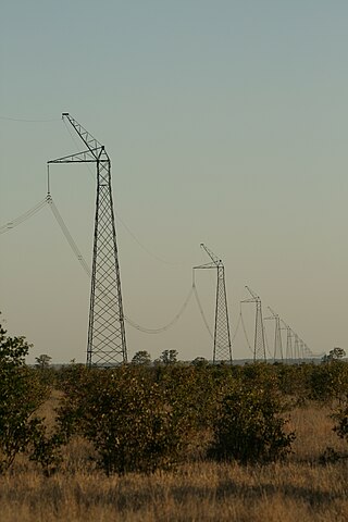
Each structure must be designed for the loads imposed on it by the conductors.[1] The weight of the conductor must be supported, as well as dynamic loads due to wind and ice accumulation, and effects of vibration. Where conductors are in a straight line, towers need only resist the weight since the tension in the conductors approximately balances with no resultant force on the structure. Flexible conductors supported at their ends approximate the form of a catenary, and much of the analysis for construction of transmission lines relies on the properties of this form.[1]
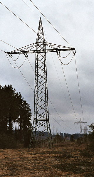
A large transmission line project may have several types of towers, with "tangent" ("suspension" or "line" towers, UK) towers intended for most positions and more heavily constructed towers used for turning the line through an angle, dead-ending (terminating) a line, or for important river or road crossings. Depending on the design criteria for a particular line, semi-flexible type structures may rely on the weight of the conductors to be balanced on both sides of each tower. More rigid structures may be intended to remain standing even if one or more conductors is broken. Such structures may be installed at intervals in power lines to limit the scale of cascading tower failures.[1]
Foundations for tower structures may be large and costly, particularly if the ground conditions are poor, such as in wetlands. Each structure may be stabilized considerably by the use of guy wires to counteract some of the forces applied by the conductors.
Power lines and supporting structures can be a form of visual pollution. In some cases the lines are buried to avoid this, but this "undergrounding" is more expensive and therefore not common.
For a single wood utility pole structure, a pole is placed in the ground, then three crossarms extend from this, either staggered or all to one side. The insulators are attached to the crossarms. For an "H"-type wood pole structure, two poles are placed in the ground, then a crossbar is placed on top of these, extending to both sides. The insulators are attached at the ends and in the middle. Lattice tower structures have two common forms. One has a pyramidal base, then a vertical section, where three crossarms extend out, typically staggered. The strain insulators are attached to the crossarms. Another has a pyramidal base, which extends to four support points. On top of this a horizontal truss-like structure is placed.
A single-circuit transmission line carries conductors for only one circuit. For a three-phase system, this implies that each tower supports three conductors.
A double-circuit transmission line has two circuits. For three-phase systems, each tower supports and insulates six conductors. Single phase AC-power lines as used for traction current have four conductors for two circuits. Usually both circuits operate at the same voltage.
In HVDC systems typically two conductors are carried per line, but in rare cases only one pole of the system is carried on a set of towers.
In some countries like Germany most power lines with voltages above 100 kV are implemented as double, quadruple or in rare cases even hextuple power line as rights of way are rare. Sometimes all conductors are installed with the erection of the pylons; often some circuits are installed later. A disadvantage of double circuit transmission lines is that maintenance can be difficult, as either work in close proximity of high voltage or switch-off of two circuits is required. In case of failure, both systems can be affected.
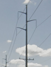
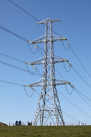
A single-circuit 138 kV line (top) with distribution wires (bottom)
A double-circuit line
Parallel single-circuit lines
Four circuits on one tower line
six circuits of three different types
Various powerlines (110/220 kV) in Germany with double and quadruple circuits
Insulators
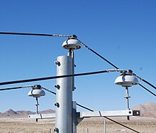
Medium-voltage power lines with ceramic insulators in CaliforniaModular suspension insulators are used for high-voltage lines.
Insulators must support the conductors and withstand both the normal operating voltage and surges due to switching and lightning. Insulators are broadly classified as either pin-type, which support the conductor above the structure, or suspension type, where the conductor hangs below the structure. The invention of the strain insulator was a critical factor in allowing higher voltages to be used.
At the end of the 19th century, the limited electrical strength of telegraph-style pin insulators limited the voltage to no more than 69,000 volts. Up to about 33 kV (69 kV in North America) both types are commonly used.[1] At higher voltages only suspension-type insulators are common for overhead conductors.
Insulators are usually made of wet-process porcelain or toughened glass, with increasing use of glass-reinforced polymer insulators. However, with rising voltage levels, polymer insulators (silicone rubber based) are seeing increasing usage.[7] China has already developed polymer insulators having a highest system voltage of 1100 kV and India is currently developing a 1200 kV (highest system voltage) line which will initially be charged with 400 kV to be upgraded to a 1200 kV line.[8]
Suspension insulators are made of multiple units, with the number of unit insulator disks increasing at higher voltages. The number of disks is chosen based on line voltage, lightning withstand requirement, altitude, and environmental factors such as fog, pollution, or salt spray. In cases where these conditions are suboptimal, longer insulators must be used. Longer insulators with longer creepage distance for leakage current, are required in these cases. Strain insulators must be strong enough mechanically to support the full weight of the span of conductor, as well as loads due to ice accumulation, and wind.[9]
Porcelain insulators may have a semi-conductive glaze finish, so that a small current (a few milliamperes) passes through the insulator. This warms the surface slightly and reduces the effect of fog and dirt accumulation. The semiconducting glaze also ensures a more even distribution of voltage along the length of the chain of insulator units.
Polymer insulators by nature have hydrophobic characteristics providing for improved wet performance. Also, studies have shown that the specific creepage distance required in polymer insulators is much lower than that required in porcelain or glass. Additionally, the mass of polymer insulators (especially in higher voltages) is approximately 50% to 30% less than that of a comparative porcelain or glass string. Better pollution and wet performance is leading to the increased use of such insulators.
Insulators for very high voltages, exceeding 200 kV, may have grading rings installed at their terminals. This improves the electric field distribution around the insulator and makes it more resistant to flash-over during voltage surges.
Conductors
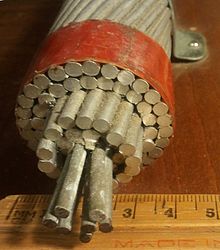
Sample cross-section of ACSR power line
The most common conductor in use for transmission today is aluminum conductor steel reinforced (ACSR). Also seeing much use is all-aluminum-alloy conductor (AAAC). Aluminum is used because it has about half the weight of a comparable resistance copper cable (though larger diameter due to lower specific conductivity), as well as being cheaper.[1] Copper was more popular in the past and is still in use, especially at lower voltages and for grounding.
While larger conductors lose less energy due to lower electrical resistance, they are more costly than smaller conductors. An optimization rule called Kelvin's Law (named for Lord Kelvin) states that the optimum size of conductor for a line is found when the cost of the energy wasted in the conductor is equal to the annual interest paid on that portion of the line construction cost due to the size of the conductors. The optimization problem is made more complex by additional factors such as varying annual load, varying cost of installation, and the discrete sizes of cable that are commonly made.[1][10]
Since a conductor is a flexible object with uniform weight per unit length, the shape of a conductor strung between two towers approximates that of a catenary. The sag of the conductor (vertical distance between the highest and lowest point of the curve) varies depending on the temperature and additional load such as ice cover. A minimum overhead clearance must be maintained for safety. Since the temperature and therefore length of the conductor increase with increasing current through it, it is sometimes possible to increase the power handling capacity (uprate) by changing the conductors for a type with a lower coefficient of thermal expansion or a higher allowable operating temperature.
Conventional ACSR (left) and modern carbon core (right) conductors
Two such conductors that offer reduced thermal sag are known as composite core conductors (ACCR and ACCC conductor). In lieu of steel core strands that are often used to increase overall conductor strength, the ACCC conductor uses a carbon and glass fiber core that offers a coefficient of thermal expansion about 1/10 of that of steel. While the composite core is nonconductive, it is substantially lighter and stronger than steel, which allows the incorporation of 28% more aluminum (using compact trapezoidal-shaped strands) without any diameter or weight penalty. The added aluminum content helps reduce line losses by 25 to 40% compared to other conductors of the same diameter and weight, depending upon electric current. The carbon core conductor's reduced thermal sag allows it to carry up to twice the current ("ampacity") compared to all-aluminum conductor (AAC) or ACSR.
For transmission of power across long distances, high voltage transmission is employed. Transmission higher than 132kV poses the problem of corona discharge, which causes significant power loss and interference with communication circuits. To reduce this corona effect, it is preferable to use more than one conductor per phase, or bundled conductors.[15]
Bundle conductors consist of several parallel cables connected at intervals by spacers, often in a cylindrical configuration. The optimum number of conductors depends on the current rating, but typically higher-voltage lines also have higher current. American Electric Power[16] is building 765kV lines using six conductors per phase in a bundle. Spacers must resist the forces due to wind, and magnetic forces during a short-circuit.
Spacer damper for four-conductor bundlesBundle conductor attachment
Bundled conductors reduce the voltage gradient in the vicinity of the line. This reduces the possibility of corona discharge. At extra high voltage, the electric field gradient at the surface of a single conductor is high enough to ionize air, which wastes power, generates unwanted audible noise and interferes with communication systems. The field surrounding a bundle of conductors is similar to the field that would surround a single, very large conductor—this produces lower gradients which mitigates issues associated with high field strength. The transmission efficiency is improved as loss due to corona effect is countered.
Bundled conductors cool themselves more efficiently due to the increased surface area of the conductors, further reducing line losses. When transmitting alternating current, bundle conductors also avoid the reduction in ampacity of a single large conductor due to the skin effect. A bundle conductor also has lower reactance, compared to a single conductor.
While wind resistance is higher, wind-induced oscillation can be damped at bundle spacers. The ice and wind loading of bundled conductors will be greater than a single conductor of the same total cross section, and bundled conductors are more difficult to install than single conductors.
Ground wires
Aluminum conductor crosslinked polyethylene insulation wire. It is used for 6600V power lines.
Overhead power lines are often equipped with a ground conductor (shield wire, static wire, or overhead earth wire). The ground conductor is usually grounded (earthed) at the top of the supporting structure, to minimize the likelihood of direct lightning strikes to the phase conductors.[17] In circuits with earthed neutral, it also serves as a parallel path with the earth for fault currents. Very high-voltage transmission lines may have two ground conductors. These are either at the outermost ends of the highest cross beam, at two V-shaped mast points, or at a separate cross arm. Older lines may use surge arresters every few spans in place of a shield wire; this configuration is typically found in the more rural areas of the United States. By protecting the line from lightning, the design of apparatus in substations is simplified due to lower stress on insulation. Shield wires on transmission lines may include optical fibers (optical ground wires/OPGW), used for communication and control of the power system.
HVDC Fenno-Skan with ground wires used as electrode line
At some HVDC converter stations, the ground wire is used also as the electrode line to connect to a distant grounding electrode. This allows the HVDC system to use the earth as one conductor. The ground conductor is mounted on small insulators bridged by lightning arrestors above the phase conductors. The insulation prevents electrochemical corrosion of the pylon.
Medium-voltage distribution lines may also use one or two shield wires, or may have the grounded conductor strung below the phase conductors to provide some measure of protection against tall vehicles or equipment touching the energized line, as well as to provide a neutral line in Wye wired systems.
On some power lines for very high voltages in the former Soviet Union, the ground wire is used for PLC systems and mounted on insulators at the pylons.
Insulated conductors and cable
Overhead insulated cables are rarely used, usually for short distances (less than a kilometer). Insulated cables can be directly fastened to structures without insulating supports. An overhead line with bare conductors insulated by air is typically less costly than a cable with insulated conductors.
A more common approach is "covered" line wire. It is treated as bare cable, but often is safer for wildlife, as the insulation on the cables increases the likelihood of a large-wing-span raptor to survive a brush with the lines, and reduces the overall danger of the lines slightly. These types of lines are often seen in the eastern United States and in heavily wooded areas, where tree-line contact is likely. The only pitfall is cost, as insulated wire is often costlier than its bare counterpart. Many utility companies implement covered line wire as jumper material where the wires are often closer to each other on the pole, such as an underground riser/pothead, and on reclosers, cutouts and the like.
A compact overhead transmission line requires a smaller right of way than a standard overhead powerline. Conductors must not get too close to each other. This can be achieved either by short span lengths and insulating crossbars, or by separating the conductors in the span with insulators. The first type is easier to build as it does not require insulators in the span, which may be difficult to install and to maintain.
Compact transmission lines may be designed for voltage upgrade of existing lines to increase the power that can be transmitted on an existing right of way.[18]
Low voltage overhead lines may use either bare conductors carried on glass or ceramic insulators or an aerial bundled cable system. The number of conductors may be anywhere between two (most likely a phase and neutral) up to as many as six (three phase conductors, separate neutral and earth plus street lighting supplied by a common switch); a common case is four (three phase and neutral, where the neutral might also serve as a protective earthing conductor).
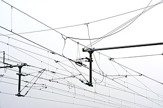
Overhead lines or overhead wires are used to transmit electrical energy to trams, trolleybuses or trains. Overhead line is designed on the principle of one or more overhead wires situated over rail tracks. Feeder stations at regular intervals along the overhead line supply power from the high-voltage grid. For some cases low-frequency AC is used, and distributed by a special traction current network.
Further applications
Overhead lines are also occasionally used to supply transmitting antennas, especially for efficient transmission of long, medium and short waves. For this purpose a staggered array line is often used. Along a staggered array line the conductor cables for the supply of the earth net of the transmitting antenna are attached on the exterior of a ring, while the conductor inside the ring, is fastened to insulators leading to the high-voltage standing feeder of the antenna.
Use of area under overhead power lines
Use of the area below an overhead line is limited because objects must not come too close to the energized conductors. Overhead lines and structures may shed ice, creating a hazard. Radio reception can be impaired under a power line, due both to shielding of a receiver antenna by the overhead conductors, and by partial discharge at insulators and sharp points of the conductors which creates radio noise.
In the area surrounding the overhead lines it is dangerous to risk interference; e.g. flying kites or balloons, using ladders or operating machinery.
Overhead distribution and transmission lines near airfields are often marked on maps, and the lines themselves marked with conspicuous plastic reflectors, to warn pilots of the presence of conductors.
Construction of overhead power lines, especially in wilderness areas, may have significant environmental effects. Environmental studies for such projects may consider the effect of bush clearing, changed migration routes for migratory animals, possible access by predators and humans along transmission corridors, disturbances of fish habitat at stream crossings, and other effects.
Aviation accidents
An aviation obstruction marker on a high-voltage overhead transmission line reminds pilots of the presence of an overhead line. Some markers are lit at night or have strobe lights.
General aviation, hang gliding, paragliding, skydiving, balloon, and kite flying must avoid accidental contact with power lines. Nearly every kite product warns users to stay away from power lines. Deaths occur when aircraft crash into power lines. Some power lines are marked with obstruction markers, especially near air strips or over waterways that may support floatplane operations. The placement of power lines sometimes use up sites that would otherwise be used by hang gliders.[19][20]
History
The first transmission of electrical impulses over an extended distance was demonstrated on July 14, 1729 by the physicist Stephen Gray.[citation needed] The demonstration used damp hemp cords suspended by silk threads (the low resistance of metallic conductors not being appreciated at the time).
However the first practical use of overhead lines was in the context of telegraphy. By 1837 experimental commercial telegraph systems ran as far as 20km (13 miles). Electric power transmission was accomplished in 1882 with the first high-voltage transmission between Munich and Miesbach (60km). 1891 saw the construction of the first three-phase alternating current overhead line on the occasion of the International Electricity Exhibition in Frankfurt, between Lauffen and Frankfurt.
In 1912 the first 110 kV-overhead power line entered service followed by the first 220 kV-overhead power line in 1923. In the 1920s RWE AG built the first overhead line for this voltage and in 1926 built a Rhine crossing with the pylons of Voerde, two masts 138 meters high.
In 1953, the first 345 kV line was put into service by American Electric Power in the United States. In Germany in 1957 the first 380 kV overhead power line was commissioned (between the transformer station and Rommerskirchen). In the same year the overhead line traversing of the Strait of Messina went into service in Italy, whose pylons served the Elbe crossing 1. This was used as the model for the building of the Elbe crossing 2 in the second half of the 1970s which saw the construction of the highest overhead line pylons of the world. Earlier, in 1952, the first 380 kV line was put into service in Sweden, in 1000km (625 miles) between the more populated areas in the south and the largest hydroelectric power stations in the north. Starting from 1967 in Russia, and also in the USA and Canada, overhead lines for voltage of 765 kV were built. In 1982 overhead power lines were built in Soviet Union between Elektrostal and the power station at Ekibastuz, this was a three-phase alternating current line at 1150 kV (Powerline Ekibastuz-Kokshetau). In 1999, in Japan the first powerline designed for 1000 kV with 2 circuits were built, the Kita-Iwaki Powerline. In 2003 the building of the highest overhead line commenced in China, the Yangtze River Crossing.
Mathematical analysis
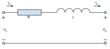
An overhead power line is one example of a transmission line. At power system frequencies, many useful simplifications can be made for lines of typical lengths. For analysis of power systems, the distributed resistance, series inductance, shunt leakage resistance and shunt capacitance can be replaced with suitable lumped values or simplified networks.
Short and medium line model
A short length of a power line (less than 80km) can be approximated with a resistance in series with an inductance and ignoring the shunt admittances. This value is not the total impedance of the line, but rather the series impedance per unit length of line. For a longer length of line (80–250km), a shunt capacitance is added to the model. In this case it is common to distribute half of the total capacitance to each side of the line. As a result, the power line can be represented as a two-port network, such as with ABCD parameters.[21]
An electrical insulator is a material in which electric current does not flow freely. The atoms of the insulator have tightly bound electrons which cannot readily move. Other materials—semiconductors and conductors—conduct electric current more easily. The property that distinguishes an insulator is its resistivity; insulators have higher resistivity than semiconductors or conductors. The most common examples are non-metals.
Electric power transmission is the bulk movement of electrical energy from a generating site, such as a power plant, to an electrical substation. The interconnected lines that facilitate this movement form a transmission network. This is distinct from the local wiring between high-voltage substations and customers, which is typically referred to as electric power distribution. The combined transmission and distribution network is part of electricity delivery, known as the electrical grid.
An overhead line or overhead wire is an electrical cable that is used to transmit electrical energy to electric locomotives, electric multiple units, trolleybuses or trams. The generic term used by the International Union of Railways for the technology is overhead line. It is known variously as overhead catenary, overhead contact line (OCL), overhead contact system (OCS), overhead equipment (OHE), overhead line equipment, overhead lines (OHL), overhead wiring (OHW), traction wire, and trolley wire.
Single-wire earth return (SWER) or single-wire ground return is a single-wire transmission line which supplies single-phase electric power from an electrical grid to remote areas at lowest cost. Its distinguishing feature is that the earth is used as the return path for the current, to avoid the need for a second wire to act as a return path.
A transmission tower is a tall structure, usually a lattice tower made of steel that is used to support an overhead power line. In electrical grids, transmission towers carry high-voltage transmission lines that transport bulk electric power from generating stations to electrical substations, from which electricity is delivered to end consumers; moreover, utility poles are used to support lower-voltage sub-transmission and distribution lines that transport electricity from substations to electricity customers.
The HVDC Volgograd–Donbass is a 475 kilometres (295 mi) long bipolar ±400 kV high voltage direct current powerline used for transmitting electric power from Volga Hydroelectric Station at Volgograd in Russia to the Donbass in eastern Ukraine and vice versa.
The Pylons of Messina are two free-standing steel towers, the Sicilian one in Torre Faro and the Calabrian one in Villa San Giovanni. They were used from 1955 to 1994 to carry a 220 kilovolt power line across the Strait of Messina, between the Scilla substation in Calabria on the Italian mainland at 38°14′42″N15°40′59″E and the Messina-Santo substation in Sicily at 38°15′57″N15°39′04″E.
An overhead line crossing is the crossing of an obstacle—such as a traffic route, a river, a valley or a strait—by an overhead power line. The style of crossing depends on the local conditions and regulations at the time the power line is constructed. Overhead line crossings can sometimes require extensive construction and can also have operational issues. In such cases, those in charge of construction should consider whether a crossing of the obstacle would be better accomplished by an underground or submarine cable.
A dead-end tower is a fully self-supporting structure used in construction of overhead power lines. A dead-end transmission tower uses horizontal strain insulators at the end of conductors. Dead-end towers may be used at a substation as a transition to a "slack span" entering the equipment, when the circuit changes to a buried cable, when a transmission line changes direction by more than a few degrees, or at intervals along a straight run to limit the extent of a catastrophic collapse.
A utility pole is a column or post, usually made out of wood or aluminum alloy, used to support overhead power lines and various other public utilities, such as electrical cable, fiber optic cable, and related equipment such as transformers and street lights. It can be referred to as a transmission pole, telephone pole, telecommunication pole, power pole, hydro pole, telegraph pole, or telegraph post, depending on its application. A Stobie pole is a multi-purpose pole made of two steel joists held apart by a slab of concrete in the middle, generally found in South Australia.
A power cable is an electrical cable, an assembly of one or more electrical conductors, usually held together with an overall sheath. The assembly is used for transmission of electrical power. Power cables may be installed as permanent wiring within buildings, buried in the ground, run overhead, or exposed. Power cables that are bundled inside thermoplastic sheathing and that are intended to be run inside a building are known as NM-B.
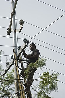
A lineworker constructs and maintains the electric transmission and distribution facilities that deliver electrical energy to industrial, commercial, and residential establishments. A lineworker installs, services, and emergency repairs electrical lines in the case of lightning, wind, ice storm, or ground disruptions. Whereas those who install and maintain electrical wiring inside buildings are electricians, lineworkers generally work at outdoor installations.
A traction network or traction power network is an electricity grid for the supply of electrified rail networks. The installation of a separate traction network generally is done only if the railway in question uses alternating current (AC) with a frequency lower than that of the national grid, such as in Germany, Austria and Switzerland.
Transposition is the periodic swapping of positions of the conductors of a transmission line, in order to reduce crosstalk and otherwise improve transmission. In telecommunications this applies to balanced pairs whilst in power transmission lines three conductors are periodically transposed.
An optical ground wire is a type of cable that is used in overhead power lines. Such cable combines the functions of grounding and communications. An OPGW cable contains a tubular structure with one or more optical fibers in it, surrounded by layers of steel and aluminum wire. The OPGW cable is run between the tops of high-voltage electricity pylons. The conductive part of the cable serves to bond adjacent towers to earth ground, and shields the high-voltage conductors from lightning strikes. The optical fibers within the cable can be used for high-speed transmission of data, either for the electrical utility's own purposes of protection and control of the transmission line, for the utility's own voice and data communication, or may be leased or sold to third parties to serve as a high-speed fiber interconnection between cities.
A strain insulator is an electrical insulator that is designed to work in mechanical tension (strain), to withstand the pull of a suspended electrical wire or cable. They are used in overhead electrical wiring, to support radio antennas and overhead power lines. A strain insulator may be inserted between two lengths of wire to isolate them electrically from each other while maintaining a mechanical connection, or where a wire attaches to a pole or tower, to transmit the pull of the wire to the support while insulating it electrically. Strain insulators were first used in telegraph systems in the mid 19th century.
An aerial cable or air cable is an insulated cable usually containing all conductors required for an electrical distribution system or a telecommunication line, which is suspended between utility poles or electricity pylons. As aerial cables are completely insulated there is no danger of electric shock when touching them and there is no requirement for mounting them with insulators on pylons and poles. A further advantage is they require less right of way than overhead lines for the same reason. They can be designed as shielded cables for telecommunication purposes. If the cable falls, it may still operate if its insulation is not damaged.
GKK Etzenricht, an abbreviation of Gleichstromkurzkupplung Etzenricht, meaning Etzenricht HVDC-back-to-back station, was an HVDC back-to-back facility near Etzenricht in the district of Neustadt an der Waldnaab in Bavaria, Germany. It was built on the site of the Etzenricht substation, a 380 kV/220 kV/110 kV-substation, which went into service in 1970 and expanded afterwards several times. The facility was used between 1993 and 1995 for the exchange of power between Germany and the Czech Republic, operated by Bayernwerk AG.
A pothead is a type of insulated electrical terminal used for transitioning between overhead line and underground high-voltage cable or for connecting overhead wiring to equipment like transformers. Its name comes from the process of potting or encapsulation of the conductors inside the terminal's insulating bushing.
Aerial bundled cables are overhead power lines using several insulated phase conductors bundled tightly together, usually with a bare neutral conductor. This contrasts with the traditional practice of using uninsulated conductors separated by air gaps. This variation of bundled conductors utilizes the same principles as overhead power lines, except that they are closer together to the point of touching but each conductor is surrounded by an insulating layer.
References
1 2 3 4 5 6 7 8 Donald G. Fink and H. Wayne Beaty, Standard Handbook for Electrical Engineers, Eleventh Edition, McGraw-Hill, New York, 1978, ISBN0-07-020974-X, Chapter 14 Overhead Power Transmission
↑ Beaty, H. Wayne; Fink, Donald G., Standard Handbook for Electrical Engineers (15th Edition) McGraw-Hill, 2007 978-0-07-144146-9 pages 14-105 through 14-106
↑ J. Glover, M. Sarma, and T. Overbye, Power System Analysis and Design, Fifth Edition, Cengage Learning, Connecticut, 2012, ISBN978-1-111-42577-7, Chapter 5 Transmission Lines: Steady-State Operation
Further reading
William D. Stevenson, Jr. Elements of Power System Analysis Third Edition, McGraw-Hill, New York (1975) ISBN0-07-061285-4
This page is based on this Wikipedia article Text is available under the CC BY-SA 4.0 license; additional terms may apply. Images, videos and audio are available under their respective licenses.