
Bandwidth is the difference between the upper and lower frequencies in a continuous band of frequencies. It is typically measured in hertz, and depending on context, may specifically refer to passband bandwidth or baseband bandwidth. Passband bandwidth is the difference between the upper and lower cutoff frequencies of, for example, a band-pass filter, a communication channel, or a signal spectrum. Baseband bandwidth applies to a low-pass filter or baseband signal; the bandwidth is equal to its upper cutoff frequency.

Code-division multiple access (CDMA) is a channel access method used by various radio communication technologies. CDMA is an example of multiple access, where several transmitters can send information simultaneously over a single communication channel. This allows several users to share a band of frequencies. To permit this without undue interference between the users, CDMA employs spread spectrum technology and a special coding scheme.
In electronics and telecommunications, modulation is the process of varying one or more properties of a periodic waveform, called the carrier signal, with a separate signal called the modulation signal that typically contains information to be transmitted. For example, the modulation signal might be an audio signal representing sound from a microphone, a video signal representing moving images from a video camera, or a digital signal representing a sequence of binary digits, a bitstream from a computer.

In telecommunications, orthogonal frequency-division multiplexing (OFDM) is a type of digital transmission used in digital modulation for encoding digital (binary) data on multiple carrier frequencies. OFDM has developed into a popular scheme for wideband digital communication, used in applications such as digital television and audio broadcasting, DSL internet access, wireless networks, power line networks, and 4G/5G mobile communications.

A delta modulation is an analog-to-digital and digital-to-analog signal conversion technique used for transmission of voice information where quality is not of primary importance. DM is the simplest form of differential pulse-code modulation (DPCM) where the difference between successive samples is encoded into n-bit data streams. In delta modulation, the transmitted data are reduced to a 1-bit data stream. Its main features are:
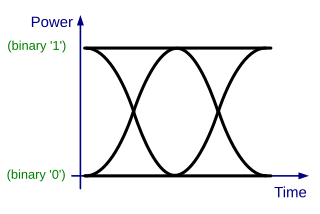
In telecommunication, an eye pattern, also known as an eye diagram, is an oscilloscope display in which a digital signal from a receiver is repetitively sampled and applied to the vertical input (y-axis), while the data rate is used to trigger the horizontal sweep (x-axis). It is so called because, for several types of coding, the pattern looks like a series of eyes between a pair of rails. It is a tool for the evaluation of the combined effects of channel noise, dispersion and intersymbol interference on the performance of a baseband pulse-transmission system. The technique was first used with the WWII SIGSALY secure speech transmission system.
In radio communication, multipath is the propagation phenomenon that results in radio signals reaching the receiving antenna by two or more paths. Causes of multipath include atmospheric ducting, ionospheric reflection and refraction, and reflection from water bodies and terrestrial objects such as mountains and buildings. When the same signal is received over more than one path, it can create interference and phase shifting of the signal. Destructive interference causes fading; this may cause a radio signal to become too weak in certain areas to be received adequately. For this reason, this effect is also known as multipath interference or multipath distortion.
In information theory, the Shannon–Hartley theorem tells the maximum rate at which information can be transmitted over a communications channel of a specified bandwidth in the presence of noise. It is an application of the noisy-channel coding theorem to the archetypal case of a continuous-time analog communications channel subject to Gaussian noise. The theorem establishes Shannon's channel capacity for such a communication link, a bound on the maximum amount of error-free information per time unit that can be transmitted with a specified bandwidth in the presence of the noise interference, assuming that the signal power is bounded, and that the Gaussian noise process is characterized by a known power or power spectral density. The law is named after Claude Shannon and Ralph Hartley.

In wireless communications, fading is variation of the attenuation of a signal with various variables. These variables include time, geographical position, and radio frequency. Fading is often modeled as a random process. A fading channel is a communication channel that experiences fading. In wireless systems, fading may either be due to multipath propagation, referred to as multipath-induced fading, weather, or shadowing from obstacles affecting the wave propagation, sometimes referred to as shadow fading.
8VSB is the modulation method used for broadcast in the ATSC digital television standard. ATSC and 8VSB modulation is used primarily in North America; in contrast, the DVB-T standard uses COFDM.

In signal processing and related disciplines, aliasing is an effect that causes different signals to become indistinguishable when sampled. It also often refers to the distortion or artifact that results when a signal reconstructed from samples is different from the original continuous signal.

A communication channel refers either to a physical transmission medium such as a wire, or to a logical connection over a multiplexed medium such as a radio channel in telecommunications and computer networking. A channel is used for information transfer of, for example, a digital bit stream, from one or several senders to one or several receivers. A channel has a certain capacity for transmitting information, often measured by its bandwidth in Hz or its data rate in bits per second.
Pulse-position modulation (PPM) is a form of signal modulation in which M message bits are encoded by transmitting a single pulse in one of possible required time shifts. This is repeated every T seconds, such that the transmitted bit rate is bits per second. It is primarily useful for optical communications systems, which tend to have little or no multipath interference.
This is an index of articles relating to electronics and electricity or natural electricity and things that run on electricity and things that use or conduct electricity.
Continuous phase modulation (CPM) is a method for modulation of data commonly used in wireless modems. In contrast to other coherent digital phase modulation techniques where the carrier phase abruptly resets to zero at the start of every symbol, with CPM the carrier phase is modulated in a continuous manner. For instance, with QPSK the carrier instantaneously jumps from a sine to a cosine whenever one of the two message bits of the current symbol differs from the two message bits of the previous symbol. This discontinuity requires a relatively large percentage of the power to occur outside of the intended band, leading to poor spectral efficiency. Furthermore, CPM is typically implemented as a constant-envelope waveform, i.e., the transmitted carrier power is constant. Therefore, CPM is attractive because the phase continuity yields high spectral efficiency, and the constant envelope yields excellent power efficiency. The primary drawback is the high implementation complexity required for an optimal receiver.
Amplitude-shift keying (ASK) is a form of amplitude modulation that represents digital data as variations in the amplitude of a carrier wave. In an ASK system, a symbol, representing one or more bits, is sent by transmitting a fixed-amplitude carrier wave at a fixed frequency for a specific time duration. For example, if each symbol represents a single bit, then the carrier signal could be transmitted at nominal amplitude when the input value is 1, but transmitted at reduced amplitude or not at all when the input value is 0.

A constellation diagram is a representation of a signal modulated by a digital modulation scheme such as quadrature amplitude modulation or phase-shift keying. It displays the signal as a two-dimensional xy-plane scatter diagram in the complex plane at symbol sampling instants. In a manner similar to that of a phasor diagram, the angle of a point, measured counterclockwise from the horizontal axis, represents the phase shift of the carrier wave from a reference phase; the distance of a point from the origin represents a measure of the amplitude or power of the signal.
The raised-cosine filter is a filter frequently used for pulse-shaping in digital modulation due to its ability to minimise intersymbol interference (ISI). Its name stems from the fact that the non-zero portion of the frequency spectrum of its simplest form is a cosine function, 'raised' up to sit above the (horizontal) axis.
In communications, the Nyquist ISI criterion describes the conditions which, when satisfied by a communication channel, result in no intersymbol interference or ISI. It provides a method for constructing band-limited functions to overcome the effects of intersymbol interference.
In electronics and telecommunications, pulse shaping is the process of changing a transmitted pulses' waveform to optimize the signal for its intended purpose or the communication channel. This is often done by limiting the bandwidth of the transmission and filtering the pulses to control intersymbol interference. Pulse shaping is particularly important in RF communication for fitting the signal within a certain frequency band and is typically applied after line coding and modulation.


