
A steam engine is a heat engine that performs mechanical work using steam as its working fluid. The steam engine uses the force produced by steam pressure to push a piston back and forth inside a cylinder. This pushing force can be transformed, by a connecting rod and crank, into rotational force for work. The term "steam engine" is generally applied only to reciprocating engines as just described, not to the steam turbine. Steam engines are external combustion engines, where the working fluid is separated from the combustion products. The ideal thermodynamic cycle used to analyze this process is called the Rankine cycle. In general usage, the term steam engine can refer to either complete steam plants, such as railway steam locomotives and portable engines, or may refer to the piston or turbine machinery alone, as in the beam engine and stationary steam engine.

Stationary steam engines are fixed steam engines used for pumping or driving mills and factories, and for power generation. They are distinct from locomotive engines used on railways, traction engines for heavy steam haulage on roads, steam cars, agricultural engines used for ploughing or threshing, marine engines, and the steam turbines used as the mechanism of power generation for most nuclear power plants.
A compound steam engine unit is a type of steam engine where steam is expanded in two or more stages. A typical arrangement for a compound engine is that the steam is first expanded in a high-pressure (HP) cylinder, then having given up heat and losing pressure, it exhausts directly into one or more larger-volume low-pressure (LP) cylinders. Multiple-expansion engines employ additional cylinders, of progressively lower pressure, to extract further energy from the steam.
Improvements to the steam engine were some of the most important technologies of the Industrial Revolution, although steam did not replace water power in importance in Britain until after the Industrial Revolution. From Englishman Thomas Newcomen's atmospheric engine, of 1712, through major developments by Scottish inventor and mechanical engineer James Watt, the steam engine began to be used in many industrial settings, not just in mining, where the first engines had been used to pump water from deep workings. Early mills had run successfully with water power, but by using a steam engine a factory could be located anywhere, not just close to a water source. Water power varied with the seasons and was not always available.
In a steam engine, cutoff is the point in the piston stroke at which the inlet valve is closed. On a steam locomotive, the cutoff is controlled by the reversing gear.

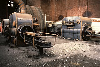
A Corliss steam engine is a steam engine, fitted with rotary valves and with variable valve timing patented in 1849, invented by and named after the American engineer George Henry Corliss of Providence, Rhode Island.

The first recorded rudimentary steam engine was the aeolipile mentioned by Vitruvius between 30 and 15 BC and, described by Heron of Alexandria in 1st-century Roman Egypt. Several steam-powered devices were later experimented with or proposed, such as Taqi al-Din's steam jack, a steam turbine in 16th-century Ottoman Egypt, and Thomas Savery's steam pump in 17th-century England. In 1712, Thomas Newcomen's atmospheric engine became the first commercially successful engine using the principle of the piston and cylinder, which was the fundamental type of steam engine used until the early 20th century. The steam engine was used to pump water out of coal mines.

An expansion valve is a device in steam engine valve gear that improves engine efficiency. It operates by closing off the supply of steam early, before the piston has travelled through its full stroke. This cut-off allows the steam to then expand within the cylinder. This expanding steam is still sufficient to drive the piston, even though its pressure decreases as it expands. As less steam is supplied in the shorter time for which the valve is open, use of the expansion valve reduces the steam consumed and thus the fuel required. The engine may deliver two-thirds of the work, for only one-third of the steam.

A shell or flued boiler is an early and relatively simple form of boiler used to make steam, usually for the purpose of driving a steam engine. The design marked a transitional stage in boiler development, between the early haystack boilers and the later multi-tube fire-tube boilers. A flued boiler is characterized by a large cylindrical boiler shell forming a tank of water, traversed by one or more large flues containing the furnace. These boilers appeared around the start of the 19th century and some forms remain in service today. Although mostly used for static steam plants, some were used in early steam vehicles, railway locomotives and ships.

A blowing engine is a large stationary steam engine or internal combustion engine directly coupled to air pumping cylinders. They deliver a very large quantity of air at a pressure lower than an air compressor, but greater than a centrifugal fan.

Musgrave's non-dead-centre engine was a stationary steam engine of unusual design, intended to solve the problem of stopping on dead centre. It was designed in 1887 to serve as a marine engine. It used a pair of linked cylinders to prevent the engine from stopping in a position where no turning force can be applied. At least one engine is known to survive.
George Saxon & Co was an English engineering company that manufactured stationary steam engines. It was based in the Openshaw district of Manchester. The company produced large steam-driven engines for power stations and later for textile mills in Lancashire and elsewhere.
Woolstenhulmes & Rye was a company that manufactured stationary steam engines. It was based in Oldham, Lancashire, England. The company produced large steam-driven engines for textile mills in Oldham and elsewhere.
Urmson & Thompson was a company that manufactured stationary steam engines. It was based in Oldham, Lancashire, England. The company were general millwrights, also producing some steam engines during the 19th century and after 1904 produced large steam-driven engines for textile mills in Oldham.
Buckley & Taylor was a British engineering company that manufactured stationary steam engines. It was the largest firm of engine makers in Oldham, Lancashire, England. The company produced large steam-driven engines for textile mills in Oldham and exported to India, Holland and Brazil.

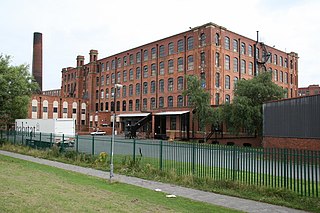
Carels Frères, or Carels Brothers, was a manufacturer of stationary steam engines in Ghent, Belgium. For instance, in 1909, they supplied a 1200 hp tandem compound engine with super heater to Moston Mill, a cotton mill in Moston, North Manchester. It was their works no 875, with cylinders 30 and 53 in bore with a 3 ft 11+1⁄4 in (1,200 mm) stroke. Developing 1,200 hp (890 kW) at 90 rpm, superheated steam 200 psi (1,379 kPa) was supplied by Tetlow boilers. The flywheel, 19 ft (5,791 mm) in diameter, was provided with the sixty rope grooves that the full power would have required. The second half of the mill, however, was never completed, and in 1958 electric drives were installed, and the engine was scrapped.
Yates & Thom Ltd, or Yates of Blackburn, was a British manufacturer of stationary steam engines and boilers at the Canal Ironworks, Blackburn, Lancashire, England.
Alexander Petrie and Co was a company that manufactured stationary steam engines. It was based in Rochdale, Greater Manchester in England. The company did general millwrighting, producing some steam engines during the 19th century. Around 1845, their superintendent, William McNaught, was producing large steam-driven beam engines for textile mills in Rochdale.

Ellenroad Mill was a cotton spinning mill in Newhey, a village in the Milnrow area of Rochdale, England. It was built as a mule spinning mill in 1890 by Stott and Sons and extended in 1899. It was destroyed by fire on 19 January 1916. When it was rebuilt, it was designed and equipped as a ring spinning mill.
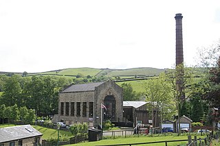
Bancroft Shed was a weaving shed in Barnoldswick, Lancashire, England, situated on the road to Skipton. Construction was started in 1914 and the shed was commissioned in 1920 for James Nutter & Sons Limited. The mill closed on 22 December 1978 and was demolished. The engine house, chimneys and boilers have been preserved and maintained as a working steam museum. The mill was the last steam-driven weaving shed to be constructed and the last to close.

