KNX

Last updated
KNX
KNX logo.svg
International standardEN 50090, ISO/IEC 14543
Industry Building automation
Website knx.org
KNX universal light dimming actuator with two channels MDT AKD-0201.02.jpg
KNX universal light dimming actuator with two channels
KNX-Transceiver-Board by Elmos Embedded World KNX TP Demo Board.jpg
KNX-Transceiver-Board by Elmos

KNX is an open standard (see EN 50090, ISO/IEC 14543) for commercial and residential building automation. KNX devices can manage lighting, blinds and shutters, HVAC, security systems, energy management, audio video, white goods, displays, remote control, etc. KNX evolved from three earlier standards; the European Home Systems Protocol (EHS), BatiBUS, and the European Installation Bus (EIB or Instabus).

Contents

It can use twisted pair (in a tree, line or star topology), powerline, RF, or IP links. On this network, the devices form distributed applications and tight interaction is possible. This is implemented via interworking models with standardised datapoint types and objects, modelling logical device channels.

Standard

The KNX standard has been built on the OSI-based EIB communication stack extended with the physical layers, configuration modes and application experience of BatiBUS and EHS.

KNX installations can use several physical communication media:

KNX is not based on a specific hardware platform and a network can be controlled by anything from an 8-bit microcontroller to a PC, according to the demands of a particular building. The most common form of installation is over twisted pair medium.

KNX is an approved standard by the following organisations, (inter alia): [1]

It is administered by the KNX Association cvba, a non-profit organisation governed by Belgian law which was formed in 1999. The KNX Association had 500 registered hardware and software vendor members from 45 nations as at 1 July 2021. It had partnership agreements with 100,000 installer companies in 172 countries and more than 500 registered training centres. [2] This is a royalty-free open standard and thus access to the KNX specifications is unrestricted. [3]

Architecture

KNX devices are commonly connected by a twisted pair bus and can be modified from a controller. The bus is routed in parallel to the electrical power supply to all devices and systems on the network linking: [4]

Classifying devices as either "sensor" or "actuator" is outdated and simplistic. Many actuators include controller functionality, but also sensor functionality (for instance measuring operating hours, number of switch cycles, current, electrical power consumption, and more).

Application software, together with system topology and commissioning software, is loaded onto the devices via a system interface component. Installed systems can be accessed via LAN, point to point links, or phone networks for central or distributed control of the system via computers, tablets and touch screens, and smartphones.

The KNX Model KNX model.jpg
The KNX Model

The key features of the KNX architecture are:

Applications, interworking and binding

Central to the KNX architecture concepts are datapoints (inputs, outputs, parameters, and diagnostic data) which represent process and control variables in the system. The standardised containers for these datapoints are group objects and interface object properties. The communication system offers a reduced instruction set to read and write datapoint values. Datapoints have to conform to standardised datapoint types, themselves grouped into functional blocks. These functional blocks and datapoint types are related to applications fields, but some of them are of general use (such as date and time). Datapoints may be accessed through unicast or multicast mechanisms.

To logically link applications' datapoints across the network, KNX has three underlying binding schemes: one for free, one for structured and one for tagged binding:

Kernel and message protocol

The common kernel sits on top of the physical layers and the medium-specific data link layer and is shared by all the devices on the KNX Network. It is OSI 7-layer model compliant:

Configuration modes

An installation has to be configured at the network topology level and at individual nodes or devices. The first level is a precondition or “bootstrap” phase, prior to the configuration of the distributed applications, i.e. binding and parameter setting. Configuration may be achieved through a combination of local activity on the devices (such pushing a button), and active network management communication over the bus (peer-to-peer, or more centralized master-slave).

The KNX configuration mode:

Some modes require more active management over the bus, whereas some others are mainly oriented towards local configuration. There are three categories of KNX devices:

KNX encompasses tools for project engineering tasks such as linking a series of individual devices into a functioning installation and integrating different media and configuration modes. This is embodied in an Engineering Tool Software (ETS) suite.

Devices

A KNX installation always consists of a set of devices connected to the bus or network. Device models vary according to node roles, capabilities, management features and configuration modes, and are all laid down in the profiles. There are also general-purpose device models, such as for bus coupling units (BCUs) or bus interface modules (BIMs).

Devices may be identified and subsequently accessed throughout the network either by their individual address, or by their unique serial number, depending on the configuration mode. (Unique serial numbers are allocated by the KNX Association Certification Department.) Devices can also disclose both a manufacturer specific reference and functional (manufacturer independent) information when queried.

Topology and addressing

A KNX wired network can be formed with tree, line and star topologies, which can be mixed as needed; ring topologies are not supported. A tree topology is recommended for a large installation.

KNX can link up to 57,375 devices using 16-bit addresses.

Coupling units allow address filtering which helps to improve performance given the limited bus signal speed. An installation based on KNXnet/IP allows the integration of KNX sub networks via IP as the KNX address structure is similar to an IP address.

Physical layer

TP 1

The TP1 twisted pair bus (inherited from EIB) provides asynchronous, character oriented data transfer and half-duplex bidirectional differential signaling with a signaling speed of 9600 bit/s. Media access control is via CSMA/CA. Every bus user has equal data transmission rights and data is exchanged directly (peer-to-peer) between bus users. SELV power is distributed via the same pair for low-power devices. A deprecated specification, TP0, running at a slower signalling speed of 4800 bit/s, has been retained from the BatiBUS standard but KNX products cannot exchange information with BatiBUS devices.

PL 110

PL 110 power-line transmission is delivered using spread frequency shift keying signalling with asynchronous transmission of data packets and half duplex bi-directional communication. It uses the central frequency 110 kHz (CENELEC B-band) and has a data rate of 1200 bit/s. It also uses CSMA. KNX Powerline is aimed at smart white goods, but the take-up has been low. An alternative variant, PL 132, has a carrier frequency centred on 132.5 kHz (CENELEC C-band).

RF

RF enables communication in the 868.3 MHz band for using frequency shift keying with Manchester data encoding.

IP

KNXnet/IP port 3671 has integration solutions for IP-enabled media like Ethernet (IEEE 802.2), Bluetooth, WiFi/Wireless LAN (IEEE 802.11), FireWire (IEEE 1394) etc.

Frame format

Ignoring any preamble for medium-specific access and collision control, a frame format is generally:

OctetRole
0control field
1 - 2source address
3 - 4destination address
5address type | NPCI | length
6 - 7Transport Layer Protocol Information | Application Layer Protocol Information | data/APCI
8 - N-1data
N ≤ 22frame check

Security

KNX Telegrams can be signed or encrypted thanks to the extension of the protocol that was developed starting in 2013, KNX Data Secure for securing telegrams on the traditional KNX media TP and RF and KNX IP Secure for securing KNX telegrams tunnelled via IP. KNX Data Secure became an EN standard (EN 50090-3-4) in 2018, KNX IP Secure an ISO standard (ISO 22510) in 2019.

Conformity

Any product labeled with the KNX trademark must be certified to conform with the standards (and thus interoperable with other devices) by accredited third party test labs. All products bearing the KNX logo are programmed through a common interface using the vendor-independent ETS software.

See also

Related Research Articles

<span class="mw-page-title-main">OSI model</span> Model of communication of seven abstraction layers

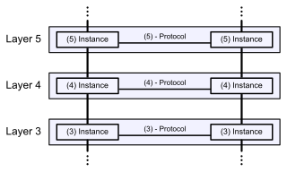
The Open Systems Interconnection model is a reference model from the International Organization for Standardization (ISO) that "provides a common basis for the coordination of standards development for the purpose of systems interconnection." In the OSI reference model, the communications between systems are split into seven different abstraction layers: Physical, Data Link, Network, Transport, Session, Presentation, and Application.

<span class="mw-page-title-main">Network topology</span> Arrangement of the elements of a communication network

Network topology is the arrangement of the elements of a communication network. Network topology can be used to define or describe the arrangement of various types of telecommunication networks, including command and control radio networks, industrial fieldbusses and computer networks.

Simple Network Management Protocol (SNMP) is an Internet Standard protocol for collecting and organizing information about managed devices on IP networks and for modifying that information to change device behavior. Devices that typically support SNMP include cable modems, routers, switches, servers, workstations, printers, and more.

Zigbee is an IEEE 802.15.4-based specification for a suite of high-level communication protocols used to create personal area networks with small, low-power digital radios, such as for home automation, medical device data collection, and other low-power low-bandwidth needs, designed for small scale projects which need wireless connection. Hence, Zigbee is a low-power, low-data-rate, and close proximity wireless ad hoc network.

<span class="mw-page-title-main">Medium access control</span> Service layer in IEEE 802 network standards

In IEEE 802 LAN/MAN standards, the medium access control (MAC), also called media access control, is the layer that controls the hardware responsible for interaction with the wired or wireless transmission medium. The MAC sublayer and the logical link control (LLC) sublayer together make up the data link layer. The LLC provides flow control and multiplexing for the logical link, while the MAC provides flow control and multiplexing for the transmission medium.

A controller area network is a vehicle bus standard designed to allow microcontrollers and devices to communicate with each other. It is a message-based protocol, designed originally for multiplex electrical wiring within automobiles to save on copper, but it can also be used in many other contexts. For each device, the data in a frame is transmitted serially but in such a way that if more than one device transmits at the same time, the highest priority device can continue while the others back off. Frames are received by all devices, including by the transmitting device.

<span class="mw-page-title-main">Profibus</span> Communications protocol

Profibus is a standard for fieldbus communication in automation technology and was first promoted in 1989 by BMBF and then used by Siemens. It should not be confused with the Profinet standard for Industrial Ethernet. Profibus is openly published as type 3 of IEC 61158/61784-1.

Modbus or MODBUS is a client/server data communications protocol in the application layer. It was originally published by Modicon in 1979 for use with its programmable logic controllers (PLCs). Modbus has become a de facto standard communication protocol for communication between industrial electronic devices in a wide range of buses and network.

EN 50090 is a European standard for Home and Building Electronic Systems (HBES) open communications, issued by CENELEC. It covers any combination of electronic devices linked via a digital transmission network to provide automated, decentralised and distributed process control for domestic and commercial and building applications; for example the control of lighting, heating, food preparation, washing, energy management, water, fire alarms, blinds, security, etc.

A fieldbus is a member of a family of industrial digital communication networks used for real-time distributed control. Fieldbus profiles are standardized by the International Electrotechnical Commission (IEC) as IEC 61784/61158.

<span class="mw-page-title-main">Profinet</span> Computer network protocol

Profinet is an industry technical standard for data communication over Industrial Ethernet, designed for collecting data from, and controlling equipment in industrial systems, with a particular strength in delivering data under tight time constraints. The standard is maintained and supported by Profibus and Profinet International, an umbrella organization headquartered in Karlsruhe, Germany.

<span class="mw-page-title-main">Computer network</span> Network that allows computers to share resources and communicate with each other

A computer network is a set of computers sharing resources located on or provided by network nodes. Computers use common communication protocols over digital interconnections to communicate with each other. These interconnections are made up of telecommunication network technologies based on physically wired, optical, and wireless radio-frequency methods that may be arranged in a variety of network topologies.

EtherCAT is an Ethernet-based fieldbus system developed by Beckhoff Automation. The protocol is standardized in IEC 61158 and is suitable for both hard and soft real-time computing requirements in automation technology.

DeviceNet is a network protocol used in the automation industry to interconnect control devices for data exchange. It utilizes the Common Industrial Protocol over a Controller Area Network media layer and defines an application layer to cover a range of device profiles. Typical applications include information exchange, safety devices, and large I/O control networks.

In computing, Microsoft's Windows Vista and Windows Server 2008 introduced in 2007/2008 a new networking stack named Next Generation TCP/IP stack, to improve on the previous stack in several ways. The stack includes native implementation of IPv6, as well as a complete overhaul of IPv4. The new TCP/IP stack uses a new method to store configuration settings that enables more dynamic control and does not require a computer restart after a change in settings. The new stack, implemented as a dual-stack model, depends on a strong host-model and features an infrastructure to enable more modular components that one can dynamically insert and remove.

Sercos III is the third generation of the Sercos interface, a standardized open digital interface for the communication between industrial controls, motion devices, input/output devices (I/O), and Ethernet nodes, such as PCs. Sercos III applies the hard real-time features of the Sercos interface to Ethernet. It is based upon and conforms to the Ethernet standard. Work began on Sercos III in 2003, with vendors releasing first products supporting it in 2005.

<span class="mw-page-title-main">IEEE 1394</span> Serial bus interface standard, also known as Firewire

IEEE 1394 is an interface standard for a serial bus for high-speed communications and isochronous real-time data transfer. It was developed in the late 1980s and early 1990s by Apple in cooperation with a number of companies, primarily Sony and Panasonic. It is most commonly known by the name FireWire (Apple), though other brand names exist such as i.LINK (Sony), and Lynx.

MOST is a high-speed multimedia network technology for the automotive industry. It can be used for applications inside or outside the car. The serial MOST bus uses a daisy-chain topology or ring topology and synchronous serial communication to transport audio, video, voice and data signals via plastic optical fiber (POF) or electrical conductor physical layers.

BatiBus was a network protocol for building automation that was introduced in 1989 and has since been succeeded by KNX. It was a relatively simple low-cost protocol that did not rely on dedicated chips.

References

  1. "What is KNX?". National KNX Norway. Archived from the original on 2015-09-25. Retrieved 2018-07-07.
  2. The current vendor list can be found at knx.org: "KNX Community".
  3. "KNX Specifications". KNX.
  4. All information in this and subsequent sections is summarised from KNX System Specifications. v3.0. Vol. Architecture. KNX Association. 2013.