A logic family of monolithic digital integrated circuit devices is a group of electronic logic gates constructed using one of several different designs, usually with compatible logic levels and power supply characteristics within a family. Many logic families were produced as individual components, each containing one or a few related basic logical functions, which could be used as "building-blocks" to create systems or as so-called "glue" to interconnect more complex integrated circuits.
Before the widespread use of integrated circuits, various solid-state and vacuum-tube logic systems were used but these were never as standardized and interoperable as the integrated-circuit devices. The most common logic family in modern semiconductor devices is metal–oxide–semiconductor (MOS) logic, due to low power consumption, small transistor sizes, and high transistor density.
Technologies
The list of packaged building-block logic families can be divided into categories, listed here in roughly chronological order of introduction, along with their usual abbreviations:
The families (RTL, DTL, and ECL) were derived from the logic circuits used in early computers, originally implemented using discrete components. One example is the PhilipsNORBIT family of logic building blocks.
The PMOS and I2L logic families were used for relatively short periods, mostly in special purpose custom large-scale integration circuits devices and are generally considered obsolete. For example, early digital clocks or electronic calculators may have used one or more PMOS devices to provide most of the logic for the finished product. The F14 CADC, Intel 4004, Intel 4040, and Intel 8008microprocessors and their support chips were PMOS.
Of these families, only ECL, TTL, NMOS, CMOS, and BiCMOS are currently still in widespread use. ECL is used for very high-speed applications because of its price and power demands, while NMOS logic is mainly used in VLSI circuits applications such as CPUs and memory chips which fall outside of the scope of this article. Present-day "building block" logic gate ICs are based on the ECL, TTL, CMOS, and BiCMOS families.
A family of simple resistor–transistor logic integrated circuits was developed at Fairchild Semiconductor for the Apollo Guidance Computer in 1962. Texas Instruments soon introduced its own family of RTL. A variant with integrated capacitors, RCTL, had increased speed, but lower immunity to noise than RTL. This was made by Texas Instruments as their "51XX" series.
Class of digital circuits in which the logic gating function (e.g., AND) is performed by a diode network and the amplifying function is performed by a transistor.
Diode logic was used with vacuum tubes in the earliest electronic computers in the 1940s including ENIAC. Diode–transistor logic (DTL) was used in the IBM 608 which was the first all-transistorized computer. Early transistorized computers were implemented using discrete transistors, resistors, diodes and capacitors.
The first diode–transistor logic family of integrated circuits was introduced by Signetics in 1962. DTL was also made by Fairchild and Westinghouse. A family of diode logic and diode–transistor logic integrated circuits was developed by Texas Instruments for the D-37CMinuteman II Guidance Computer in 1962, but these devices were not available to the public.
A variant of DTL called "high-threshold logic" incorporated Zener diodes to create a large offset between logic 1 and logic 0 voltage levels. These devices usually ran off a 15 volt power supply and were found in industrial control, where the high differential was intended to minimize the effect of noise.[3]
For devices of equal current driving capability, n-channel MOSFETs can be made smaller than p-channel MOSFETs, due to p-channel charge carriers (holes) having lower mobility than do n-channel charge carriers (electrons), and producing only one type of MOSFET on a silicon substrate is cheaper and technically simpler. These were the driving principles in the design of NMOS logic which uses n-channel MOSFETs exclusively. However, neglecting leakage current, unlike CMOS logic, NMOS logic consumes power even when no switching is taking place.
Mohamed M. Atalla and Dawon Kahng, after they invented the MOSFET, fabricated both pMOS and nMOS devices with a 20 μm process in 1960.[4] Their original MOSFET devices had a gate length of 20μm and a gate oxide thickness of 100 nm.[5] However, the nMOS devices were impractical, and only the pMOS type were practical working devices.[4] A more practical NMOS process was developed several years later. NMOS was initially faster than CMOS, thus NMOS was more widely used for computers in the 1970s.[6] With advances in technology, CMOS logic displaced NMOS logic in the mid-1980s to become the preferred process for digital chips.
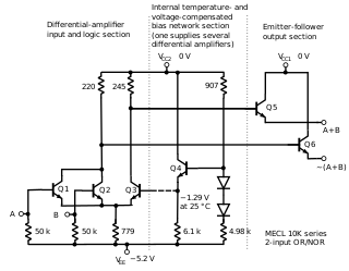
ECL uses an overdriven bipolar junction transistor (BJT) differential amplifier with single-ended input and limited emitter current.
The ECL family, ECL is also known as current-mode logic (CML), was invented by IBM as current steering logic for use in the transistorizedIBM 7030 Stretch computer, where it was implemented using discrete components.
The first ECL logic family to be available in integrated circuits was introduced by Motorola as MECL in 1962.[7]
The first transistor–transistor logic family of integrated circuits was introduced by Sylvania as Sylvania Universal High–Level Logic (SUHL) in 1963. Texas Instruments introduced the 7400 series TTL family in 1964. Transistor–transistor logic uses bipolar transistors to form its integrated circuits.[8] TTL has changed significantly over the years, with newer versions replacing the older types.
Since the transistors of a standard TTL gate are saturated switches, minority carrier storage time in each junction limits the switching speed of the device. Variations on the basic TTL design are intended to reduce these effects and improve speed, power consumption, or both.
The German physicist Walter H. Schottky formulated a theory predicting the Schottky effect, which led to the Schottky diode and later Schottky transistors. For the same power dissipation, Schottky transistors have a faster switching speed than conventional transistors because the Schottky diode prevents the transistor from saturating and storing charge; see Baker clamp. Gates built with Schottky transistors use more power than normal TTL and switch faster.[clarification needed] With Low-power Schottky (LS), internal resistance values were increased to reduce power consumption and increase switching speed over the original version. The introduction of Advanced Low-power Schottky (ALS) further increased speed and reduced power consumption. A faster logic family called FAST (Fairchild Advanced Schottky TTL) (Schottky) (F) was also introduced that was faster than normal Schottky TTL.
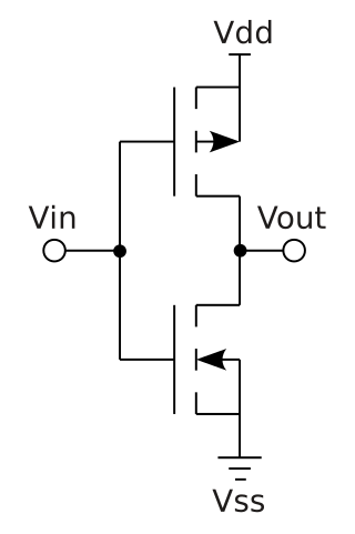
CMOS logic gates use complementary arrangements of enhancement-mode N-channel and P-channel field effect transistor. Since the initial devices used oxide-isolated metal gates, they were called CMOS (complementary metal–oxide–semiconductor logic). In contrast to TTL, CMOS uses almost no power in the static state (that is, when inputs are not changing). A CMOS gate draws no current other than leakage when in a steady 1 or 0 state. When the gate switches states, current is drawn from the power supply to charge the capacitance at the output of the gate. This means that the current draw of CMOS devices increases with switching rate (controlled by clock speed, typically).
The first CMOS family of logic integrated circuits was introduced by RCA as CD4000 COS/MOS, the 4000 series, in 1968. Initially CMOS logic was slower than LS-TTL. However, because the logic thresholds of CMOS were proportional to the power supply voltage, CMOS devices were well-adapted to battery-operated systems with simple power supplies. CMOS gates can also tolerate much wider voltage ranges than TTL gates because the logic thresholds are (approximately) proportional to power supply voltage, and not the fixed levels required by bipolar circuits.
The required silicon area for implementing such digital CMOS functions has rapidly shrunk. VLSI technology incorporating millions of basic logic operations onto one chip, almost exclusively uses CMOS. The extremely small capacitance of the on-chip wiring caused an increase in performance by several orders of magnitude. On-chip clock rates as high as 4GHz have become common, approximately 1000 times faster than the technology by 1970.
CMOS chips often work with a broader range of power supply voltages than other logic families. Early TTL ICs required a power supplyvoltage of 5V, but early CMOS could use 3 to 15V.[9] Lowering the supply voltage reduces the charge stored on any capacitances and consequently reduces the energy required for a logic transition. Reduced energy implies less heat dissipation. The energy stored in a capacitance C and changing V volts is ½CV2. By lowering the power supply from 5V to 3.3V, switching power was reduced by almost 60 percent (power dissipation is proportional to the square of the supply voltage). Many motherboards have a voltage regulator module to provide the even lower power supply voltages required by many CPUs.
HC logic
Because of the incompatibility of the CD4000 series of chips with the previous TTL family, a new standard emerged which combined the best of the TTL family with the advantages of the CD4000 family. It was known as the 74HC (which used anywhere from 3.3V to 5V power supplies (and used logic levels relative to the power supply)), and with devices that used 5V power supplies and TTL logic levels.
The CMOS–TTL logic level problem
Interconnecting any two logic families often required special techniques such as additional pull-up resistors, or purpose-built interface circuits, since the logic families may use different voltage levels to represent 1 and 0 states, and may have other interface requirements only met within the logic family.
TTL logic levels are different from those of CMOS – generally a TTL output does not rise high enough to be reliably recognized as a logic 1 by a CMOS input. This problem was solved by the invention of the 74HCT family of devices that uses CMOS technology but TTL input logic levels. These devices only work with a 5V power supply. They form a replacement for TTL, although HCT is slower than original TTL (HC logic has about the same speed as original TTL).
One major improvement was to combine CMOS inputs and TTL drivers to form of a new type of logic devices called BiCMOS logic, of which the LVT and ALVT logic families are the most important. The BiCMOS family has many members, including ABT logic, ALB logic, ALVT logic, BCT logic and LVT logic.
Improved versions
With HC and HCT logic and LS-TTL logic competing in the market it became clear that further improvements were needed to create the ideal logic device that combined high speed, with low power dissipation and compatibility with older logic families. A whole range of newer families has emerged that use CMOS technology. A short list of the most important family designators of these newer devices includes:
The integrated injection logic (IIL or I2L) uses bipolar transistors in a current-steering arrangement to implement logic functions.[12] It was used in some integrated circuits, but it is now considered obsolete.[13]
The following logic families would either have been used to build up systems from functional blocks such as flip-flops, counters, and gates, or else would be used as "glue" logic to interconnect very-large scale integration devices such as memory and processors. Not shown are some early obscure logic families from the early 1960s such as DCTL (direct-coupled transistor logic), which did not become widely available.
Propagation delay is the time taken for a two-input NAND gate to produce a result after a change of state at its inputs. Toggle speed represents the fastest speed at which a J-K flip flop could operate. Power per gate is for an individual 2-input NAND gate; usually there would be more than one gate per IC package. Values are very typical and would vary slightly depending on application conditions, manufacturer, temperature, and particular type of logic circuit. Introduction year is when at least some of the devices of the family were available in volume for civilian uses. Some military applications pre-dated civilian use.[14][15]
Introduced by Signetics, Fairchild 930 line became industry standard in 1964
PMOS
MEM 1000
300
1
9
-27 and -13
1967
Introduced by General Instrument
CMOS
AC/ACT
3
125
0.5
3.3 or 5 (2-6 or 4.5-5.5)
1985
ACT has TTL compatible levels
CMOS
HC/HCT
9
50
0.5
5 (2-6 or 4.5-5.5)
1982
HCT has TTL compatible levels
CMOS
4000B/74C
30
5
1.2
10V (3-18)
1970
Approximately half speed and power at 5 volts
TTL
Original series
10
25
10
5 (4.75-5.25)
1964
Several manufacturers
TTL
L
33
3
1
5 (4.75-5.25)
1964
Low power
TTL
H
6
43
22
5 (4.75-5.25)
1964
High speed
TTL
S
3
100
19
5 (4.75-5.25)
1969
Schottky high speed
TTL
LS
10
40
2
5 (4.75-5.25)
1976
Low power Schottky high speed
TTL
ALS
4
50
1.3
5 (4.5-5.5)
1976
Advanced Low power Schottky
TTL
F
3.5
100
5.4
5 (4.75-5.25)
1979
Fast
TTL
AS
2
105
8
5 (4.5-5.5)
1980
Advanced Schottky
TTL
G
1.5
1125 (1.125GHz)
1.65 - 3.6
2004
First GHz 7400 series logic
ECL
ECL III
1
500
60
-5.2(-5.19 - -5.21)
1968
Improved ECL
ECL
MECL I
8
31
-5.2
1962
first integrated logic circuit commercially produced
ECL
ECL 10K
2
125
25
-5.2(-5.19 - -5.21)
1971
Motorola
ECL
ECL 100K
0.75
350
40
-4.5(-4.2 - -5.2)
1981
ECL
ECL 100KH
1
250
25
-5.2(-4.9 - -5.5)
1981
On-chip design styles
Several techniques and design styles are primarily used in designing large single-chip application-specific integrated circuits (ASIC) and CPUs, rather than generic logic families intended for use in multi-chip applications.
A logic gate is a device that performs a Boolean function, a logical operation performed on one or more binary inputs that produces a single binary output. Depending on the context, the term may refer to an ideal logic gate, one that has, for instance, zero rise time and unlimited fan-out, or it may refer to a non-ideal physical device.
A transistor is a semiconductor device used to amplify or switch electrical signals and power. It is one of the basic building blocks of modern electronics. It is composed of semiconductor material, usually with at least three terminals for connection to an electronic circuit. A voltage or current applied to one pair of the transistor's terminals controls the current through another pair of terminals. Because the controlled (output) power can be higher than the controlling (input) power, a transistor can amplify a signal. Some transistors are packaged individually, but many more in miniature form are found embedded in integrated circuits. Because transistors are the key active components in practically all modern electronics, many people consider them one of the 20th century's greatest inventions.
The metal–oxide–semiconductor field-effect transistor is a type of field-effect transistor (FET), most commonly fabricated by the controlled oxidation of silicon. It has an insulated gate, the voltage of which determines the conductivity of the device. This ability to change conductivity with the amount of applied voltage can be used for amplifying or switching electronic signals. The term metal–insulator–semiconductor field-effect transistor (MISFET) is almost synonymous with MOSFET. Another near-synonym is insulated-gate field-effect transistor (IGFET).
Transistor–transistor logic (TTL) is a logic family built from bipolar junction transistors. Its name signifies that transistors perform both the logic function and the amplifying function, as opposed to earlier resistor–transistor logic (RTL) and diode–transistor logic (DTL).
NMOS or nMOS logic uses n-type (-) MOSFETs to implement logic gates and other digital circuits.
Complementary metal–oxide–semiconductor is a type of metal–oxide–semiconductor field-effect transistor (MOSFET) fabrication process that uses complementary and symmetrical pairs of p-type and n-type MOSFETs for logic functions. CMOS technology is used for constructing integrated circuit (IC) chips, including microprocessors, microcontrollers, memory chips, and other digital logic circuits. CMOS technology is also used for analog circuits such as image sensors, data converters, RF circuits, and highly integrated transceivers for many types of communication.
In digital logic, an inverter or NOT gate is a logic gate which implements logical negation. It outputs a bit opposite of the bit that is put into it. The bits are typically implemented as two differing voltage levels.
In electronics, emitter-coupled logic (ECL) is a high-speed integrated circuit bipolar transistor logic family. ECL uses an overdriven bipolar junction transistor (BJT) differential amplifier with single-ended input and limited emitter current to avoid the saturated region of operation and its slow turn-off behavior. As the current is steered between two legs of an emitter-coupled pair, ECL is sometimes called current-steering logic (CSL), current-mode logic (CML) or current-switch emitter-follower (CSEF) logic.
The 7400 series is a popular logic family of transistor–transistor logic (TTL) integrated circuits (ICs).
Resistor–transistor logic (RTL), sometimes also known as transistor–resistor logic (TRL), is a class of digital circuits built using resistors as the input network and bipolar junction transistors (BJTs) as switching devices. RTL is the earliest class of transistorized digital logic circuit; it was succeeded by diode–transistor logic (DTL) and transistor–transistor logic (TTL).
IC power-supply pins denote a voltage and current supply terminals in electric, electronics engineering, and in integrated circuit design. Integrated circuits (ICs) have at least two pins that connect to the power rails of the circuit in which they are installed. These are known as the power-supply pins. However, the labeling of the pins varies by IC family and manufacturer. The double subscript notation usually corresponds to a first letter in a given IC family (transistors) notation of the terminals.
An electronic component is any basic discrete electronic device or physical entity part of an electronic system used to affect electrons or their associated fields. Electronic components are mostly industrial products, available in a singular form and are not to be confused with electrical elements, which are conceptual abstractions representing idealized electronic components and elements. A datasheet for an electronic component is a technical document that provides detailed information about the component's specifications, characteristics, and performance.
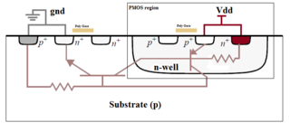
In electronics, a latch-up is a type of short circuit which can occur in an integrated circuit (IC). More specifically, it is the inadvertent creation of a low-impedance path between the power supply rails of a MOSFET circuit, triggering a parasitic structure which disrupts proper functioning of the part, possibly even leading to its destruction due to overcurrent. A power cycle is required to correct this situation.
In integrated circuits, depletion-load NMOS is a form of digital logic family that uses only a single power supply voltage, unlike earlier NMOS logic families that needed more than one different power supply voltage. Although manufacturing these integrated circuits required additional processing steps, improved switching speed and the elimination of the extra power supply made this logic family the preferred choice for many microprocessors and other logic elements.
PMOS or pMOS logic is a family of digital circuits based on p-channel, enhancement mode metal–oxide–semiconductor field-effect transistors (MOSFETs). In the late 1960s and early 1970s, PMOS logic was the dominant semiconductor technology for large-scale integrated circuits before being superseded by NMOS and CMOS devices.
A transistor is a semiconductor device with at least three terminals for connection to an electric circuit. In the common case, the third terminal controls the flow of current between the other two terminals. This can be used for amplification, as in the case of a radio receiver, or for rapid switching, as in the case of digital circuits. The transistor replaced the vacuum-tube triode, also called a (thermionic) valve, which was much larger in size and used significantly more power to operate. The first transistor was successfully demonstrated on December 23, 1947, at Bell Laboratories in Murray Hill, New Jersey. Bell Labs was the research arm of American Telephone and Telegraph (AT&T). The three individuals credited with the invention of the transistor were William Shockley, John Bardeen and Walter Brattain. The introduction of the transistor is often considered one of the most important inventions in history.
The following outline is provided as an overview of and topical guide to electronics:
The field-effect transistor (FET) is a type of transistor that uses an electric field to control the flow of current in a semiconductor. It comes in two types: junction FET (JFET) and metal-oxide-semiconductor FET (MOSFET). FETs have three terminals: source, gate, and drain. FETs control the flow of current by the application of a voltage to the gate, which in turn alters the conductivity between the drain and source.
The memory cell is the fundamental building block of computer memory. The memory cell is an electronic circuit that stores one bit of binary information and it must be set to store a logic 1 and reset to store a logic 0. Its value is maintained/stored until it is changed by the set/reset process. The value in the memory cell can be accessed by reading it.
This page is based on this Wikipedia article Text is available under the CC BY-SA 4.0 license; additional terms may apply. Images, videos and audio are available under their respective licenses.