Maximum power point tracking

Last updated
Power/Voltage-curve of a partially shaded PV system, with marked local and global MPP UP-curve of partially shaded solar generator.png
Power/Voltage-curve of a partially shaded PV system, with marked local and global MPP

Maximum power point tracking (MPPT), [1] [2] or sometimes just power point tracking (PPT), [3] [4] is a technique used with variable power sources to maximize energy extraction as conditions vary. The technique is most commonly used with photovoltaic (PV) solar systems, but can also be used with wind turbines, optical power transmission and thermophotovoltaics.

Contents

PV solar systems have varying relationships to inverter systems, external grids, battery banks, and other electrical loads. [5] The central problem addressed by MPPT is that the efficiency of power transfer from the solar cell depends on the amount of available sunlight, shading, solar panel temperature and the load's electrical characteristics. As these conditions vary, the load characteristic (impedance) that gives the highest power transfer changes. The system is optimized when the load characteristic changes to keep power transfer at highest efficiency. This optimal load characteristic is called the maximum power point (MPP). MPPT is the process of adjusting the load characteristic as the conditions change. Circuits can be designed to present optimal loads to the photovoltaic cells and then convert the voltage, current, or frequency to suit other devices or systems.

Solar cells' non-linear relationship between temperature and total resistance can be analyzed based on the Current-voltage (I-V) curve and the power-voltage (P-V) curves. [6] [7] MPPT samples cell output and applies the proper resistance (load) to obtain maximum power. [8] MPPT devices are typically integrated into an electric power converter system that provides voltage or current conversion, filtering, and regulation for driving various loads, including power grids, batteries, or motors. Solar inverters convert DC power to AC power and may incorporate MPPT.

The power at the MPP (Pmpp) is the product of the MPP voltage (Vmpp) and MPP current (Impp).

In general, the P-V curve of a partially shaded solar array can have multiple peaks, and some algorithms can get stuck in a local maximum rather than the global maximum of the curve. [9]

Background

Photovoltaic solar cell I-V curves where a line intersects the knee of the curves where the maximum power transfer point is located. Solar-Cell-IV-curve-with-MPP.png
Photovoltaic solar cell I-V curves where a line intersects the knee of the curves where the maximum power transfer point is located.

Photovoltaic cells have a complex relationship between their operating environment and the power they produce. The nonlinear I-V curve characteristic of a given cell in specific temperature and insolation conditions can be functionally characterized by a fill factor (FF). Fill factor is defined as the ratio of the maximum power from the cell to the product of open circuit voltage Voc and short-circuit current Isc. Tabulated data is often used to estimate the maximum power that a cell can provide with an optimal load under given conditions:

.

For most purposes, FF, Voc, and Isc are enough information to give a useful approximate view of the cell's electrical behavior under typical conditions.

For any given set of conditions, cells have a single operating point where the values of the current (I) and voltage (V) of the cell allow maximum power output. [10] These values correspond to a particular load resistance, which is equal to V / I as specified by Ohm's law. The power P is given by P=V I.

A photovoltaic cell, for the majority of its useful curve, acts as a constant current source. [11] However, at a photovoltaic cell's MPP region, its curve has an approximately inverse exponential relationship between current and voltage. From basic circuit theory, the power delivered to a device is optimized (MPP) where the derivative (graphically, the slope) dI/dV of the I-V curve is equal and opposite the I/V ratio (where dP/dV=0) [12] and corresponds to the "knee" of the curve.

A load with resistance R=V/I equal to the reciprocal of this value draws the maximum power from the device. This is sometimes called the 'characteristic resistance' of the cell. This is a dynamic quantity that changes depending on the level of illumination, as well as other factors such as temperature and cell condition. Lower or higher resistance reduces power output. Maximum power point trackers utilize control circuits or logic to identify this point.

Power-voltage (P-V) curve Power-voltage (P -V) curve.png
Power-voltage (P-V) curve

If a full power-voltage (P-V) curve is available, then the maximum power point can be obtained using a bisection method.

Implementation

When directly connecting a load to cell, the operating point of the panel is rarely at peak power. The impedance seen by the panel determines its operating point. Setting the impedance correctly achieves peak power. Since panels are DC devices, DC-DC converters transform the impedance of one circuit (source) to the other circuit (load). Changing the duty ratio of the DC-DC converter changes the impedance (duty ratio) seen by the cell. The I-V curve of the panel can be considerably affected by atmospheric conditions such as irradiance and temperature.

MPPT algorithms frequently sample panel voltages and currents, then adjust the duty ratio accordingly. Microcontrollers implement the algorithms. Modern implementations often utilize more sophisticated computers for analytics and load forecasting.

Classification

Controllers can follow several strategies to optimize power output. MPPTs may switch among multiple algorithms as conditions dictate. [13]

Perturb and observe

In this method the controller adjusts the voltage from the array by a small amount and measures power; if the power increases, further adjustments in that direction are tried until power no longer increases. This is called perturb and observe (P&O) and is most common, although this method can cause power output to oscillate. [14] [15] It is also referred to as a hill climbing method, because it depends on the rise of the curve of power against voltage below the maximum power point, and the fall above that point. [16] Perturb and observe is the most commonly used method due to its ease of implementation. [14] Perturb and observe method may result in top-level efficiency, provided that a proper predictive and adaptive hill climbing strategy is adopted. [17] [18]

Incremental conductance

In this method, the controller measures incremental current and voltage changes to predict the effect of a voltage change. This method requires more computation in the controller, but can track changing conditions more rapidly than P&O. Power output does not oscillate. [19] It utilizes the incremental conductance () of the photovoltaic array to compute the sign of the change in power with respect to voltage (). [20] The incremental conductance method computes MPP by comparison of the incremental conductance () to the array conductance (). When these two are the same (), the output voltage is the MPP voltage. The controller maintains this voltage until the irradiation changes and the process is repeated.

The incremental conductance method is based on the observation that at MPP, , and that . The current from the array can be expressed as a function of the voltage:

.

Therefore, . Setting this equal to zero yields: . Therefore, MPP is achieved when the incremental conductance is equal to the negative of the instantaneous conductance. The power-voltage curve characteristic shows that: when the voltage is smaller than MPP, , so ; when the voltage is bigger than MPP, or . Thus, a tracker can know where it is on the power-voltage curve by calculating the relation of the change of current/voltage and the current voltage themselves.

Current sweep

The current sweep method uses a sweep waveform for the array current such that the I-V characteristic of the PV array is obtained and updated at fixed time intervals. MPP voltage can then be computed from the characteristic curve at the same intervals. [21] [22]

Constant voltage

Constant voltage methods include one in which the output voltage is regulated to a constant value under all conditions and one in which the output voltage is regulated based on a constant ratio to the measured open circuit voltage (). The latter technique may also be labeled the "open voltage" method. [23] If the output voltage is held constant, there is no attempt to track MPP, so it is not strictly a MPPT technique, though it does function in cases when MPP tracking tends to fail, and thus it is sometimes used supplementally. In the open voltage method, power delivery is momentarily interrupted and the open-circuit voltage with zero current is measured. The controller then resumes operation with the voltage controlled at a fixed ratio, such as 0.76, of the open-circuit voltage . [24] This is usually a value that has been predetermined to be the MPP, either empirically or based on modelling, for expected operating conditions. [19] [20] The array's operating point is thus kept near MPP by regulating the array voltage and matching it to the fixed reference voltage . The value of may be chosen to give optimal performance relative to other factors as well as the MPP, but the central idea is that is determined as a ratio to . One of the inherent approximations in the method is that the ratio of MPP voltage to is only approximately constant, so it leaves room for further possible optimization.

Temperature method

This method estimates the MPP voltage () by measuring the temperature of the solar module and comparing it against a reference. [25] Since changes in irradiation levels have a negligible effect on the MPP voltage, its influences may be ignored - the voltage is assumed to vary linearly with temperature.

This algorithm calculates the following equation:

,

where:

is the voltage at the maximum power point for a given temperature;
is a reference temperature;
is the measured temperature;
is the temperature coefficient of (available in the datasheet).

Advantages

  • Simplicity: This algorithm solves one linear equation. Therefore, it requires little computation.
  • Can be implemented as an analog or digital circuit.
  • Since temperature varies slowly with time, oscillation and instability are non-factors.
  • Low cost: temperature sensors are usually cheap.
  • Robust against noise.

Disadvantages

  • Estimation error might not be negligible for low irradiation levels (e.g. below 200 W/m2).

Comparison of methods

Both P&O and incremental conductance are examples of "hill climbing" methods that can find the local maximum of the power curve for the array's operating condition, and so provide a true MPP. [6] [16] [19]

P&O produces power output oscillations around the maximum power point even under steady state irradiance.

Incremental conductance can determine the maximum power point without oscillating. [14] It can perform MPPT under rapidly varying irradiation conditions with higher accuracy than P&O. [14] However, this method can produce oscillations and can perform erratically under rapidly changing atmospheric conditions. The sampling frequency is decreased due to the higher complexity of the algorithm compared to P&O. [20]

In the constant voltage ratio (or "open voltage") method, energy may be lost during the time the current is set to zero. [20] The approximation of 76% as the ratio is not necessarily accurate. [20] Although simple and low-cost to implement, the interruptions reduce array efficiency and do not ensure finding the actual MPP. However, efficiencies of some systems may reach above 95%. [24]

Placement

Traditional solar inverters perform MPPT for the entire array. In such systems the same current, dictated by the inverter, flows through all modules in the string (series). Because different modules have different I-V curves and different MPPs (due to manufacturing tolerance, partial shading, [26] etc.) this architecture means some modules will be performing below their MPP, costing efficiency. [27]

Instead, MPPTs can be deployed for individual modules, allowing each to operate at peak efficiency despite uneven shading, soiling or electrical mismatch.

Data suggest having one inverter with one MPPT for a project that has identical number of east and west-facing modules presents no disadvantages when compared to having two inverters or one inverter with more than one MPPT. [28]

Battery operation

At night, an off-grid PV system may use batteries to supply loads. Although the fully charged battery pack voltage may be close to the PV panel's MPP voltage, this is unlikely to be true at sunrise when the battery is partially discharged. Charging may begin at a voltage considerably below the PV panel MPP voltage, and an MPPT can resolve this mismatch.

When the batteries are fully charged and PV production exceeds local loads, an MPPT can no longer operate the panel at its MPP as the excess power has no load to absorb it. The MPPT must then shift the PV panel operating point away from the peak power point until production matches demand. (An alternative approach commonly used in spacecraft is to divert surplus PV power into a resistive load, allowing the panel to operate continuously at its peak power point in order to keep the panel as cool as possible. [29] )

In a grid-connected system, all delivered power from solar modules is sent to the grid. Therefore, the MPPT in a grid connected system always attempts to operate at MPP.

Related Research Articles

<span class="mw-page-title-main">Photovoltaics</span> Method to produce electricity from solar radiation

Photovoltaics (PV) is the conversion of light into electricity using semiconducting materials that exhibit the photovoltaic effect, a phenomenon studied in physics, photochemistry, and electrochemistry. The photovoltaic effect is commercially used for electricity generation and as photosensors.

<span class="mw-page-title-main">Solar inverter</span> Converts output of a photovoltaic panel into a utility frequency alternating current

A solar inverter or photovoltaic (PV) inverter is a type of power inverter which converts the variable direct current (DC) output of a photovoltaic solar panel into a utility frequency alternating current (AC) that can be fed into a commercial electrical grid or used by a local, off-grid electrical network. It is a critical balance of system (BOS)–component in a photovoltaic system, allowing the use of ordinary AC-powered equipment. Solar power inverters have special functions adapted for use with photovoltaic arrays, including maximum power point tracking and anti-islanding protection.

<span class="mw-page-title-main">Solar cell</span> Photodiode used to produce power from light on a large scale

A solar cell or photovoltaic cell is an electronic device that converts the energy of light directly into electricity by means of the photovoltaic effect. It is a form of photoelectric cell, a device whose electrical characteristics vary when it is exposed to light. Individual solar cell devices are often the electrical building blocks of photovoltaic modules, known colloquially as "solar panels". Almost all commercial PV cells consist of crystalline silicon, with a market share of 95%. Cadmium telluride thin-film solar cells account for the remainder. The common single-junction silicon solar cell can produce a maximum open-circuit voltage of approximately 0.5 to 0.6 volts.

<span class="mw-page-title-main">Solar panel</span> Assembly of photovoltaic cells used to generate electricity

A solar panel is a device that converts sunlight into electricity by using photovoltaic (PV) cells. PV cells are made of materials that produce excited electrons when exposed to light. The electrons flow through a circuit and produce direct current (DC) electricity, which can be used to power various devices or be stored in batteries. Solar panels are also known as solar cell panels, solar electric panels, or PV modules.

<span class="mw-page-title-main">Solar-powered pump</span> Pump that uses solar energy

Solar-powered pumps run on electricity generated by photovoltaic (PV) panels or the radiated thermal energy available from collected sunlight as opposed to grid electricity- or diesel-run water pumps. Generally, solar-powered pumps consist of a solar panel array, solar charge controller, DC water pump, fuse box/breakers, electrical wiring, and a water storage tank. The operation of solar-powered pumps is more economical mainly due to the lower operation and maintenance costs and has less environmental impact than pumps powered by an internal combustion engine. Solar pumps are useful where grid electricity is unavailable or impractical, and alternative sources do not provide sufficient energy.

<span class="mw-page-title-main">Solar tracker</span> Device that orients a payload towards the Sun

A solar tracker is a device that orients a payload toward the Sun. Payloads are usually solar panels, parabolic troughs, Fresnel reflectors, lenses, or the mirrors of a heliostat.

<span class="mw-page-title-main">Stand-alone power system</span>

A stand-alone power system, also known as remote area power supply (RAPS), is an off-the-grid electricity system for locations that are not fitted with an electricity distribution system. Typical SAPS include one or more methods of electricity generation, energy storage, and regulation.

Thermophotonics is a concept for generating usable power from heat which shares some features of thermophotovoltaic (TPV) power generation. Thermophotonics was first publicly proposed by solar photovoltaic researcher Martin Green in 2000. However, no TPX device is known to have been demonstrated to date, apparently because of the stringent requirement on the emitter efficiency.

<span class="mw-page-title-main">Charge controller</span> Battery current regulator

A charge controller, charge regulator or battery regulator limits the rate at which electric current is added to or drawn from electric batteries to protect against electrical overload, overcharging, and may protect against overvoltage. This prevents conditions that reduce battery performance or lifespan and may pose a safety risk. It may also prevent completely draining a battery, or perform controlled discharges, depending on the battery technology, to protect battery life. The terms "charge controller" or "charge regulator" may refer to either a stand-alone device, or to control circuitry integrated within a battery pack, battery-powered device, and/or battery charger.

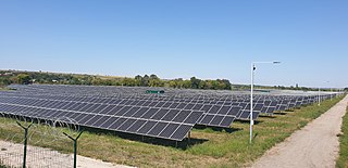
A photovoltaic system, also called a PV system or solar power system, is an electric power system designed to supply usable solar power by means of photovoltaics. It consists of an arrangement of several components, including solar panels to absorb and convert sunlight into electricity, a solar inverter to convert the output from direct to alternating current, as well as mounting, cabling, and other electrical accessories to set up a working system. Many utility-scale PV systems use tracking systems that follow the sun's daily path across the sky to generate more electricity than fixed-mounted systems.

<span class="mw-page-title-main">Multi-junction solar cell</span> Solar power cell with multiple band gaps from different materials

Multi-junction (MJ) solar cells are solar cells with multiple p–n junctions made of different semiconductor materials. Each material's p-n junction will produce electric current in response to different wavelengths of light. The use of multiple semiconducting materials allows the absorbance of a broader range of wavelengths, improving the cell's sunlight to electrical energy conversion efficiency.

<span class="mw-page-title-main">Shockley–Queisser limit</span> Maximum theoretical efficiency of a solar cell

In physics, the radiative efficiency limit is the maximum theoretical efficiency of a solar cell using a single p-n junction to collect power from the cell where the only loss mechanism is radiative recombination in the solar cell. It was first calculated by William Shockley and Hans-Joachim Queisser at Shockley Semiconductor in 1961, giving a maximum efficiency of 30% at 1.1 eV. The limit is one of the most fundamental to solar energy production with photovoltaic cells, and is one of the field's most important contributions.

<span class="mw-page-title-main">Thin-film solar cell</span> Type of second-generation solar cell

Thin-film solar cells are made by depositing one or more thin layers of photovoltaic material onto a substrate, such as glass, plastic or metal. Thin-film solar cells are typically a few nanometers (nm) to a few microns (μm) thick–much thinner than the wafers used in conventional crystalline silicon (c-Si) based solar cells, which can be up to 200 μm thick. Thin-film solar cells are commercially used in several technologies, including cadmium telluride (CdTe), copper indium gallium diselenide (CIGS), and amorphous thin-film silicon.

A power optimizer is a DC to DC converter technology developed to maximize the energy harvest from solar photovoltaic or wind turbine systems. They do this by individually tuning the performance of the panel or wind turbine through maximum power point tracking, and optionally tuning the output to match the performance of the string inverter. Power optimizers are especially useful when the performance of the power generating components in a distributed system will vary widely, such as due to differences in equipment, shading of light or wind, or being installed facing different directions or widely separated locations.

<span class="mw-page-title-main">Concentrator photovoltaics</span> Use of mirror or lens assemblies to generate current from multi-junction solar cells

Concentrator photovoltaics (CPV) is a photovoltaic technology that generates electricity from sunlight. Unlike conventional photovoltaic systems, it uses lenses or curved mirrors to focus sunlight onto small, highly efficient, multi-junction (MJ) solar cells. In addition, CPV systems often use solar trackers and sometimes a cooling system to further increase their efficiency.

<span class="mw-page-title-main">Theory of solar cells</span>

The theory of solar cells explains the process by which light energy in photons is converted into electric current when the photons strike a suitable semiconductor device. The theoretical studies are of practical use because they predict the fundamental limits of a solar cell, and give guidance on the phenomena that contribute to losses and solar cell efficiency.

<span class="mw-page-title-main">Solar-cell efficiency</span> Ratio of energy extracted from sunlight in solar cells

Solar-cell efficiency refers to the portion of energy in the form of sunlight that can be converted via photovoltaics into electricity by the solar cell.

<span class="mw-page-title-main">Rooftop solar power</span> Type of photovoltaic system

A rooftop solar power system, or rooftop PV system, is a photovoltaic (PV) system that has its electricity-generating solar panels mounted on the rooftop of a residential or commercial building or structure. The various components of such a system include photovoltaic modules, mounting systems, cables, solar inverters and other electrical accessories.

<span class="mw-page-title-main">Photovoltaic system performance</span>

Photovoltaic system performance is a function of the climatic conditions, the equipment used and the system configuration. PV performance can be measured as the ratio of actual solar PV system output vs expected values, the measurement being essential for proper solar PV facility's operation and maintenance. The primary energy input is the global light irradiance in the plane of the solar arrays, and this in turn is a combination of the direct and the diffuse radiation.

<span class="mw-page-title-main">Photovoltaic module analysis techniques</span>

Multiple different photovoltaic module analysis techniques are available and necessary for the inspection of photovoltaic (PV) modules, the detection of occurring degradation and the analysis of cell properties.

References

  1. Seyedmahmoudian, M.; Horan, B.; Soon, T. Kok; Rahmani, R.; Than Oo, A. Muang; Mekhilef, S.; Stojcevski, A. (2016-10-01). "State of the art artificial intelligence-based MPPT techniques for mitigating partial shading effects on PV systems – A review". Renewable and Sustainable Energy Reviews. 64: 435–455. doi:10.1016/j.rser.2016.06.053.
  2. Seyedmahmoudian, Mehdi; Horan, Ben; Rahmani, Rasoul; Maung Than Oo, Aman; Stojcevski, Alex (2016-03-02). "Efficient Photovoltaic System Maximum Power Point Tracking Using a New Technique". Energies. 9 (3): 147. doi: 10.3390/en9030147 . hdl: 10536/DRO/DU:30083526 .
  3. "What is Maximum Power Point Tracking (MPPT)". Northern Arizona Wind & Sun.
  4. Ali, Ali Nasr Allah; Saied, Mohamed H.; Mostafa, M; Abdel-Moneim, T. M. (2012). "A survey of maximum PPT techniques of PV systems". 2012 IEEE Energytech. pp. 1–17. doi:10.1109/EnergyTech.2012.6304652. ISBN   978-1-4673-1835-8. S2CID   10207856.
  5. Seyedmahmoudian, M.; Rahmani, R.; Mekhilef, S.; Maung Than Oo, A.; Stojcevski, A.; Soon, Tey Kok; Ghandhari, A. S. (2015-07-01). "Simulation and Hardware Implementation of New Maximum Power Point Tracking Technique for Partially Shaded PV System Using Hybrid DEPSO Method". IEEE Transactions on Sustainable Energy. 6 (3): 850–862. Bibcode:2015ITSE....6..850S. doi:10.1109/TSTE.2015.2413359. ISSN   1949-3029. S2CID   34245477.
  6. 1 2 Seyedmahmoudian, Mohammadmehdi; Mohamadi, Arash; Kumary, Swarna (2014). "A Comparative Study on Procedure and State of the Art of Conventional Maximum Power Point Tracking Techniques for Photovoltaic System". International Journal of Computer and Electrical Engineering. 6 (5): 402–414. doi: 10.17706/ijcee.2014.v6.859 .
  7. Seyedmahmoudian, Mohammadmehdi; Mekhilef, Saad; Rahmani, Rasoul; Yusof, Rubiyah; Renani, Ehsan Taslimi (2013-01-04). "Analytical Modeling of Partially Shaded Photovoltaic Systems". Energies. 6 (1): 128–144. doi: 10.3390/en6010128 . hdl: 10536/DRO/DU:30080850 .
  8. Surawdhaniwar, Sonali; Diwan, Ritesh (July 2012). "Study of Maximum Power Point Tracking Using Perturb and Observe Method". International Journal of Advanced Research in Computer Engineering & Technology. 1 (5): 106–110.
  9. Baba, Ali Omar; Liu, Guangyu; Chen, Xiaohui (2020). "Classification and Evaluation Review of Maximum Power Point Tracking Methods". Sustainable Futures. 2: 100020. doi: 10.1016/j.sftr.2020.100020 . S2CID   219879843.
  10. Seyedmahmoudian, Mohammadmehdi; Mekhilef, Saad; Rahmani, Rasoul; Yusof, Rubiyah; Shojaei, Ali Asghar (2014-03-01). "Maximum power point tracking of partial shaded photovoltaic array using an evolutionary algorithm: A particle swarm optimization technique". Journal of Renewable and Sustainable Energy. 6 (2): 023102. doi:10.1063/1.4868025. hdl: 1959.3/440382 . ISSN   1941-7012.
  11. "University of Chicago GEOS24705 Solar Photovoltaics EJM May 2011" (PDF).
  12. Sze, Simon M. (1981). Physics of Semiconductor Devices (2nd ed.). Wiley. p.  796. ISBN   9780471056614.
  13. Rahmani, R.; Seyedmahmoudian, M.;, Mekhilef, S.; Yusof, R.; 2013. Implementation of fuzzy logic maximum power point tracking controller for photovoltaic system. American Journal of Applied Sciences, 10: 209-218.
  14. 1 2 3 4 "Maximum Power Point Tracking". zone.ni.com. Archived from the original on 2011-04-16. Retrieved 2011-06-18.
  15. "Advanced Algorithm for MPPT Control of Photovoltaic System" (PDF). solarbuildings.ca. Archived from the original (PDF) on 2013-12-19. Retrieved 2013-12-19.
  16. 1 2 Hohm, D. P.; Ropp, M. E. (2003). "Comparative Study of Maximum Power Point Tracking Algorithms". Progress in Photovoltaics: Research and Applications. 11: 47–62. doi: 10.1002/pip.459 . S2CID   10668678.
  17. "Performances Improvement of Maximum Power Point Tracking Perturb and Observe Method". actapress.com. 2006-03-09. Retrieved 2011-06-18.
  18. Zhang, Q.; Hu, C.; Chen, L.; Amirahmadi, A.; Kutkut, N.; Batarseh, I. (2014). "A Center Point Iteration MPPT Method With Application on the Frequency-Modulated LLC Microinverter". IEEE Transactions on Power Electronics . 29 (3): 1262–1274. Bibcode:2014ITPE...29.1262Z. doi:10.1109/tpel.2013.2262806. S2CID   29377646.
  19. 1 2 3 "Evaluation of Micro Controller Based Maximum Power Point Tracking Methods Using dSPACE Platform" (PDF). itee.uq.edu.au. Archived from the original (PDF) on 2011-07-26. Retrieved 2011-06-18.
  20. 1 2 3 4 5 "MPPT algorithms". powerelectronics.com. April 2009. Retrieved 2011-06-10.
  21. Esram, Trishan; Chapman, P. L. (2007). "Comparison of Photovoltaic Array Maximum Power Point Tracking Techniques". IEEE Transactions on Energy Conversion. 22 (2): 439–449. Bibcode:2007ITEnC..22..439E. doi:10.1109/TEC.2006.874230. S2CID   31354655.
  22. Bodur, Mehmet; Ermis, M. (1994). "Maximum power point tracking for low power photovoltaic solar panels". Proceedings of MELECON '94. Mediterranean Electrotechnical Conference. pp. 758–761. doi:10.1109/MELCON.1994.380992. ISBN   0-7803-1772-6. S2CID   60529406.
  23. "Energy comparison of MPPT techniques for PV Systems" (PDF). wseas. Retrieved 2011-06-18.
  24. 1 2 Ferdous, S.M.; Mohammad, Mahir Asif; Nasrullah, Farhan; Saleque, Ahmed Mortuza; Muttalib, A.Z.M.Shahriar (2012). 2012 7th International Conference on Electrical and Computer Engineering. pp. 908–911. doi:10.1109/ICECE.2012.6471698. ISBN   978-1-4673-1436-7. S2CID   992906.
  25. Coelho, Roberto F.; Concer, Filipe M.; Martins, Denizar C. (December 2010). "A MPPT approach based on temperature measurements applied in PV systems". 2010 IEEE International Conference on Sustainable Energy Technologies (ICSET). IEEE. pp. 1–6. doi:10.1109/icset.2010.5684440. ISBN   978-1-4244-7192-8.
  26. Seyedmahmoudian, M.; Mekhilef, S.; Rahmani, R.; Yusof, R.; Renani, E.T. Analytical Modeling of Partially Shaded Photovoltaic Systems. Energies 2013, 6, 128-144.
  27. "Invert your thinking: Squeezing more power out of your solar panels". blogs.scientificamerican.com. Retrieved 2015-05-05.
  28. "InterPV.net - Global PhotoVoltaic Business Magazine". interpv.net.
  29. "solar cell - Why is it desired to divert the surplus PV power into a resistive load?". Electrical Engineering Stack Exchange.

Further reading

Commons-logo.svg Media related to Maximum power point tracker at Wikimedia Commons