Niobium capacitor

Last updated

SMD chip style of niobium electrolytic capacitors Nb-SMD-Electrolytic capacitors.png
SMD chip style of niobium electrolytic capacitors

A niobium electrolytic capacitor (historically also Columbium capacitor [1] [2] ) is an electrolytic capacitor whose anode (+) is made of passivated niobium metal or niobium monoxide, on which an insulating niobium pentoxide layer acts as a dielectric. A solid electrolyte on the surface of the oxide layer serves as the capacitor's cathode (−).

Contents

Niobium capacitors are available in SMD packaging and compete with tantalum chip capacitors in certain voltage and capacitance ratings. They are available with a solid manganese dioxide electrolyte.

Like most electrolytic capacitors, niobium capacitors are polarized components. Reverse voltages or ripple currents higher than specified tolerances can destroy the dielectric and thus the capacitor; the resulting short circuit can cause a fire or explosion in larger units.

Niobium capacitors were developed in the United States and the Soviet Union in the 1960s. Since 2002 they have been commercially available in the West, taking advantage of the lower cost and better availability of niobium relative to tantalum.

Basic information

Niobium is a sister metal to tantalum. Niobium has a similar melting point (2744 °C) to tantalum and exhibits similar chemical properties. The materials and processes used to produce niobium-dielectric capacitors are essentially the same as for existing tantalum-dielectric capacitors. However, niobium as a raw material is much more abundant in nature than tantalum and is less expensive. The characteristics of niobium electrolytic capacitors and tantalum electrolytic capacitors are roughly comparable.

Niobium electrolytic capacitors can be made with high purity niobium as the anode but the diffusion of oxygen from the dielectric (Nb2O5) into the niobium anode metal is very high, resulting in leakage current instability or even capacitor failures. There are two possible ways to reduce oxygen diffusion and improve leakage current stability – either by doping metallic niobium powders with nitride into passivated niobium nitride or using niobium oxide (NbO) as anode material. Niobium oxide is a hard ceramic material characterized by high metallic conductivity. Niobium oxide powder can be prepared in a similar structure to that of tantalum powder and can be processed in a similar way to produce capacitors. It also can be oxidized by anodic oxidation (anodizing, forming) to generate the insulating dielectric layer. Thus two types of niobium electrolytic capacitors are marketed, those using a passivated niobium anode and those using a niobium oxide anode. Both types use niobium pentoxide (Nb2O5) as the dielectric layer.

Anodic oxidation

Diagram illustrating anodic oxidation, in which a metallic anode in an electrolyte forms an oxide layer in response to the application of voltage. Anodic oxidation.jpg
Diagram illustrating anodic oxidation, in which a metallic anode in an electrolyte forms an oxide layer in response to the application of voltage.

Niobium, similarly to tantalum and aluminum, is a so-called valve metal. Placing such a metal in contact with an electrolytic bath and applying a positive voltage to it forms a layer of electrically insulating oxide whose thickness corresponds to the applied voltage. This oxide layer acts as the dielectric in an electrolytic capacitor.

This property of niobium was known since the beginning of the 20th century. Although niobium is more abundant in nature and less expensive than tantalum, its high melting point of 2744 °C hindered the development of niobium electrolytic capacitors.

In the 1960s, the higher availability of niobium ore compared with tantalum ore prompted research into niobium electrolytic capacitors in the Soviet Union. [3] Here they served the same purpose as tantalum capacitors in the West. With the collapse of the Iron Curtain, the technology became better-known in the West, with major capacitor manufacturers taking interest in the late 1990s. The materials and processes used to produce niobium capacitors are essentially the same as for tantalum capacitors. Rising tantalum prices in 2000 and 2001 encouraged the development of niobium electrolytic capacitors with manganese dioxide and polymer electrolytes, which have been available since 2002. [4] [5]

A dielectric material is placed between two conducting plates (electrodes), each of area A and with a separation of d. Parallel plate capacitor.svg
A dielectric material is placed between two conducting plates (electrodes), each of area A and with a separation of d.

Every electrolytic capacitor can be thought of as a "plate capacitor" whose capacitance increases with the electrode area (A) and the dielectric permittivity (ε), and decreases with the dielectric thickness (d).

The dielectric thickness of niobium electrolytic capacitors is very thin, in the range of nanometers per volt. [6] This very thin dielectric layer, combined with a sufficiently high dielectric strength, allows niobium electrolytic capacitors to achieve a high volumetric capacitance comparable to tantalum capacitors.

The niobium anode material is manufactured from a powder sintered into a pellet with a rough surface structure intended to increase the electrode surface area A compared to a smooth surface with the same footprint. This increase in surface area can increase the capacitance by a factor of up to 200 for solid niobium electrolytic capacitors, depending on the rated voltage. [7]

The properties of the niobium pentoxide dielectric layer, compared with a tantalum pentoxide layer, are given in the following table: [8]

Characteristics of the different tantalum and niobium oxide layers
Anode materialDielectricRelative permittivityOxide structureBreakdown voltage (V/μm)Dielectric layer thickness (nm/V)
TantalumTantalum pentoxide Ta2O527amorphous6251.6
Niobium or Niobium oxideNiobium pentoxide Nb2O541amorphous4002.5

The higher permittivity and lower breakdown voltage of niobium pentoxide relative to tantalum pentoxide results in niobium capacitors and tantalum capacitors having similar sizes for a given capacitance.

Basic construction of solid niobium electrolytic capacitors

A typical niobium capacitor is a chip capacitor and consists of niobium or niobium oxide powder pressed and sintered into a pellet as the anode of the capacitor, with the oxide layer of niobium pentoxide as dielectric, and a solid manganese dioxide electrolyte as the cathode.

Comparison of niobium and tantalum electrolytic capacitor types

The combination of anode materials for niobium and tantalum electrolytic capacitors and the electrolytes used has formed a wide variety of capacitor types with different properties. An outline of the main characteristics of the different types is shown in the table below.

Overview of the key features of niobium and tantalum electrolytic capacitors
Electrolytic capacitor familyElectrolyteCapacitance range (μF)Max. rated voltage (V)Max. temperature (°C)
Tantalum electrolytic capacitor, sintered anodeNon-solid, sulfuric acid0.1...18,000630125/200
Solid, manganese dioxide0.1...3,300125125/150
Solid, polymer10...1,50025105
Niobium oxide electrolytic capacitor, sintered anodeSolid, manganese dioxide1...1,50010105
Solid, polymer4.7...47016105

Tantalum and niobium electrolytic capacitors with solid electrolyte as surface-mountable chip capacitors are mainly used in electronic devices in which little space is available or a low profile is required. They operate reliably over a wide temperature range without large parameter deviations. [4] [6] [8] [9] [10]

Comparison of electrical parameters of niobium and tantalum capacitor types

In order to compare the different characteristics of the different electrolytic chip capacitor types, specimens with the same dimensions and of comparable capacitance and voltage are compared in the following table. In such a comparison the values for ESR and ripple current load are the most important parameters for the use of electrolytic capacitors in modern electronic equipment. The lower the ESR the higher the ripple current per volume, thus the better the functionality of the capacitor in the circuit.

Comparison of the most important characteristics of different types of electrolytic chip capacitors
Electrolytic capacitor familyType 1Dimension DxL, WxHxL (mm)Max. ESR 100 kHz, 20 °C (mΩ)Max. Ripple current 85/105 °C (mA)Max. Leakage current after 2 Min. 2 (μA)
Tantalum capacitors, MnO2 electrolyteKemet T494 330/107.3x4.3x4.0100128510 (0.01CV)
Tantalum capacitors, Multianode, MnO2 electrolyteKemet T510 330/107.3x4.3x4.035250010 (0.01CV)
Tantalum capacitors, Polymer electrolyteKemet T543 330/107.3x4.3x4.0104900100 (0.1CV)
Tantalum capacitors, Multianode, polymerKemet T530 150/107.3x4.3x4.054970100 (0.1CV)
Niobium capacitors, MnO2 electrolyteAVX,NOS 220/6,37.3x4.3x4.180146120 (0.02CV)
Niobium capacitors, Multianode, MnO2 electrolyteAVX,NBM 220/6.37.3x4.3x4.140256120 (0.02CV)
Niobium-caps Polymer electrolyteNEC, NMC 100/107.3x4.3x2.8--20 (0.02CV)
Aluminum capacitors, Polymer electrolytePanasonic SP-UE 180/6.37.3x4.3x4.273700100 (0.1CV)
Aluminum capacitors, Polymer electrolyteKemet A700 100/107.3x4.3x4.010470040 (0.04CV)

(1) 100 μF/10 V, unless otherwise specified,

(2) calculated for a capacitor 100 μF/10 V,

History

The phenomenon that can electrochemically form an oxide layer on aluminum and metals like tantalum or niobium, blocking an electric current in one direction but allowing it to flow in the other direction, was discovered in 1875 by the French researcher Eugène Ducretet. He coined the term "valve metal" for such metals. Charles Pollak (born Karol Pollak) used this phenomenon for an idea of a polarized "Electric liquid capacitor with aluminum electrodes". In 1896 Pollak obtained a patent for the first electrolytic capacitor. [11] The first tantalum electrolytic capacitors with wound tantalum foils and non-solid electrolyte were developed in 1930 by Tansitor Electronics Inc., USA, and used for military purposes. [12]

The development of solid electrolyte tantalum capacitors began in the early 1950s as a miniaturized, more reliable low-voltage support capacitor to complement the newly invented transistor. The solution found by R. L. Taylor and H. E. Haring of the Bell Labs was based on experience with ceramics. They ground down tantalum to a powder, pressed this powder into a cylindrical form and then sintered the powder particles into a pellet ("slug") at high temperatures, between 1500 and 2000 °C, under vacuum conditions. [13] [14] These first sintered tantalum capacitors used a non-solid electrolyte not consistent with the concept of solid state electronics. 1952 a targeted search in the Bell Labs for a solid electrolyte by D. A. McLean and F. S. Power led to the invention of manganese dioxide as a solid electrolyte for a sintered tantalum capacitor. [15]

Electrical characteristics

Series-equivalent circuit

Series-equivalent circuit model of a tantalum capacitor Electrolytic capacitor model.svg
Series-equivalent circuit model of a tantalum capacitor

Niobium electrolytic capacitors as discrete components are not ideal capacitors, they have losses and parasitic inductive parts. All properties can be defined and specified by a series equivalent circuit composed out of an idealized capacitance and additional electrical components which model all losses and inductive parameters of a capacitor. In this series-equivalent circuit the electrical characteristics are defined by:

Using a series equivalent circuit instead of a parallel equivalent circuit is specified by IEC/EN 60384-1.

Capacitance standard values and tolerances

The electrical characteristics of niobium electrolytic capacitors depend on structure of the anode and the type of electrolyte. The capacitance value of the capacitor depends on measuring frequency and temperature. The rated capacitance value or nominal value is specified in the data sheets of the manufacturers and is symbolized CR CN. The standardized measuring condition for electrolytic capacitors is an AC measuring method with a frequency of 100/120 Hz. The AC measuring voltage shall not exceed 0,5  V  AC-RMS.

The percentage of allowed deviation of the measured capacitance from the rated value is called capacitance tolerance. Electrolytic capacitors are available in different tolerance series, whose values are specified in the E series specified in IEC 60063. For abbreviated marking in tight spaces, a letter code for each tolerance is specified in IEC 60062.

Rated and category voltage

Relation between rated and category voltage and rated and category temperature Rated-Category.png
Relation between rated and category voltage and rated and category temperature

Referring to IEC/EN 60384-1 standard the allowed operating voltage for niobium capacitors is called "rated voltage UR " or "nominal voltage UN". The rated voltage UR is the maximum DC voltage or peak pulse voltage that may be applied continuously at any temperature within the rated temperature range TR (IEC/EN 60384-1).

The voltage proof of electrolytic capacitors decreases with increasing temperature. For some applications it is important to use a higher temperature range. Lowering the voltage applied at a higher temperature maintains safety margins. For some capacitor types therefore the IEC standard specifies a "temperature derated voltage" for a higher temperature, the "category voltage UC". The category voltage is the maximum DC voltage or peak pulse voltage that may be applied continuously to a capacitor at any temperature within the category temperature range TC. The relation between both voltages and temperatures is given in the picture right (or above, on mobile devices).

Lower voltage applied may have positive influences for tantalum (and niobium) electrolytic capacitors. Lowering the voltage applied increases the reliability and reduces the expected failure rate. [16]

Applying a higher voltage than specified may destroy electrolytic capacitors.

Surge Voltage

The surge voltage indicates the maximum peak voltage value that may be applied to electrolytic capacitors during their application for a limited number of cycles. The surge voltage is standardized in IEC/EN 60384-1. For niobium electrolytic capacitors the surge voltage shall be not higher than round 1.3 times of the rated voltage, rounded off to the nearest volt. The surge voltage applied to niobium capacitors may influence the capacitors failure rate.

Reverse voltage

Like other electrolytic capacitors, niobium electrolytic capacitors are polarized and require the anode electrode voltage to be positive relative to the cathode voltage.

Impedance, ESR and dissipation factor, ripple current , leakage current

General information to impedance, ESR, dissipation factor tan δ, ripple current, and leakage current see electrolytic capacitor

Reliability and life time

For general information on reliability and failure rate see electrolytic capacitor.

The life time, service life, load life or useful life of electrolytic capacitors is a special characteristic of non-solid electrolytic capacitors, especially non-solid aluminum electrolytic capacitors. Their liquid electrolyte can evaporate over time, leading to wear-out failures. Solid niobium capacitors with manganese dioxide electrolyte have no wear-out mechanism, so the constant failure rate lasts up to the point when all capacitors have failed. They don't have a life time specification like non-solid aluminum electrolytic capacitors.

However, solid polymer niobium electrolytic capacitors do have a life time specification. The electrolyte deteriorates by a thermal degradation mechanism of the conductive polymer. The electrical conductivity decreases, as a function of time, in agreement with a granular structure, in which aging is due to the shrinking of the conductive polymer grains. [17] The life time of polymer electrolytic capacitors is specified in similar terms like non-solid e-caps but its life time calculation follows other rules leading to much longer operational life times. [18] [19] [20]

Failure modes, self-healing mechanism and application rules

The different types of electrolytic capacitors show different behaviors in long-term stability, inherent failure modes and their self-healing mechanisms. Application rules for types with an inherent failure mode are specified to ensure capacitors high reliability and long life.

Long-term electrical behavior, failure modes, self-healing mechanism, and application rules of the different types of electrolytic capacitors
Type of electrolytic capacitorsLong-term electrical behaviorFailure modesSelf-healing mechanismApplication rules
Tantalum e-caps solid MnO2 electrolytestableField crystallization [21] [22] Thermally induced insulating of faults in the dielectric by decomposition of the electrolyte MnO2 into insulating Mn2O3 if current availability is limitedVoltage derating 50% Series resistance 3 Ω/V [23] [24]
Tantalum e-caps solid polymer electrolyteDeterioration of conductivity, ESR increasesField crystallization [21] [22] Insulating of faults in the dielectric by oxidation or evaporation of the polymer electrolyteVoltage derating 20% [23] [24]
Niobium e-caps, solid MnO2 electrolytestableno unique determinableThermally induced insulation of faults in the dielectric by reduction of Nb2O5 into insulating NbO2niobium anode: voltage derating 50% niobium oxide anode: voltage derating 20% [23] [24]
Self-healing in solid niobium capacitors with manganese dioxide electrolyte Self-Healing-Nb-MnO2-E-Caps.jpg
Self-healing in solid niobium capacitors with manganese dioxide electrolyte

A rare failure in solid electrolytic capacitors is breakdown of the dielectric caused by faults or impurities. In niobium electrolytic capacitors the dielectric is niobium pentoxide (Nb2O5). Besides this pentoxide there is an additional niobium suboxide, niobium dioxide (NbO2). The NbO2 is a semi-conducting material with a higher conductivity than Nb2O5 but much lower than a short. In case of faults or impurities in the dielectric which evokes a partial dielectric breakdown the conducting channel would be effectively isolated by reduction of Nb2O5 into high ohmic NbO2 if energy is limited.

As more energy is applied to a faulty solid niobium eventually either the high ohmic NbO2 channel or the Nb2O5 dielectric breaks down and the capacitor exhibits a thermal runaway failure. In comparison to solid tantalum capacitors the thermal runaway of niobium anodes will occur at about three times higher power than of tantalum anodes. This gives a significant reduction (95%) of the ignition failure mode compared to solid tantalum capacitors.

The dielectric layer Nb2O5 of solid niobium electrolytic capacitors has a lower breakdown voltage proof than Ta2O5 in tantalum capacitors and therefore grows thicker per applied volt and so operates at lower field strength for a given voltage rating with the lower electrical stress the dielectric. In combination with niobium oxide anodes, which are more stable against oxygen diffusion that results in lower voltage derating rules compared with passivated niobium or tantalum anodes. [8]

Additional information

Capacitor symbols

Electrolytic capacitor symbols

Polarized capacitor symbol.png Polarized capacitor symbol 2.png Polarized capacitor symbol 3.png
Electrolytic capacitorElectrolytic capacitorElectrolytic capacitor

Polarity marking

Niobium electrolytic chip capacitors are marked with a bar at the positive component side Polymer-Quader-Polaritat.jpg
Niobium electrolytic chip capacitors are marked with a bar at the positive component side

Niobium capacitors are in general polarized components, with distinctly marked positive terminals. When subjected to reversed polarity (even briefly), the capacitor depolarizes and the dielectric oxide layer breaks down, which can cause it to fail even when later operated with correct polarity. If the failure is a short circuit (the most common occurrence), and current is not limited to a safe value, catastrophic thermal runaway may occur.

Standardization

The standardization for all electrical, electronic components and related technologies follows the rules given by the International Electrotechnical Commission (IEC), [25] a non-profit, non-governmental international standards organization. [26] [27] The definition of the characteristics and the procedure of the test methods for capacitors for use in electronic equipment are set out in the generic specification:

Until now (2014) no IEC detail specification for niobium electrolytic capacitors is available.

For electronics manufacturers in the United States the EIA publish a standard for niobium and tantalum chip capacitors:

Features

See also

Related Research Articles

A photoflash capacitor is an electrolytic capacitor used in flash cameras, professional flashes, and also in solid-state laser power supplies. Their usual purpose is to briefly power a high-voltage flash tube, used to illuminate a photographic subject or optically pump a laser rod. As flash tubes require very high current for a very short time to operate, photoflash capacitors are designed to supply high discharge current pulses without excessive internal heating.

<span class="mw-page-title-main">Electrolytic capacitor</span> Type of capacitor

An electrolytic capacitor is a polarized capacitor whose anode or positive plate is made of a metal that forms an insulating oxide layer through anodization. This oxide layer acts as the dielectric of the capacitor. A solid, liquid, or gel electrolyte covers the surface of this oxide layer, serving as the cathode or negative plate of the capacitor. Because of their very thin dielectric oxide layer and enlarged anode surface, electrolytic capacitors have a much higher capacitance-voltage (CV) product per unit volume than ceramic capacitors or film capacitors, and so can have large capacitance values. There are three families of electrolytic capacitor: aluminium electrolytic capacitors, tantalum electrolytic capacitors, and niobium electrolytic capacitors.

Capacitors and inductors as used in electric circuits are not ideal components with only capacitance or inductance. However, they can be treated, to a very good degree of approximation, as being ideal capacitors and inductors in series with a resistance; this resistance is defined as the equivalent series resistance (ESR). If not otherwise specified, the ESR is always an AC resistance, which means it is measured at specified frequencies, 100 kHz for switched-mode power supply components, 120 Hz for linear power-supply components, and at its self-resonant frequency for general-application components. Additionally, audio components may report a "Q factor", incorporating ESR among other things, at 1000 Hz.

<span class="mw-page-title-main">Anodizing</span> Metal treatment process

Anodizing is an electrolytic passivation process used to increase the thickness of the natural oxide layer on the surface of metal parts.

<span class="mw-page-title-main">Capacitor types</span> Manufacturing styles of an electronic device

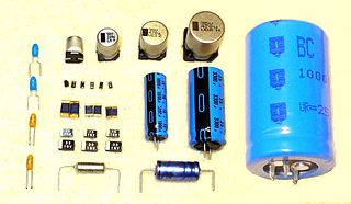
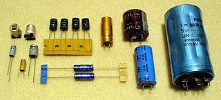
Capacitors are manufactured in many styles, forms, dimensions, and from a large variety of materials. They all contain at least two electrical conductors, called plates, separated by an insulating layer (dielectric). Capacitors are widely used as parts of electrical circuits in many common electrical devices.

<span class="mw-page-title-main">Tantalum pentoxide</span> Chemical compound

Tantalum pentoxide, also known as tantalum(V) oxide, is the inorganic compound with the formula Ta
2
O
5
. It is a white solid that is insoluble in all solvents but is attacked by strong bases and hydrofluoric acid. Ta
2
O
5
is an inert material with a high refractive index and low absorption, which makes it useful for coatings. It is also extensively used in the production of capacitors, due to its high dielectric constant.

<span class="mw-page-title-main">Capacitor</span> Passive two-terminal electronic component that stores electrical energy in an electric field

A capacitor is an electronic device that stores electrical energy in an electric field by accumulating electric charges on two closely spaced surfaces that are insulated from each other. It is a passive electronic component with two terminals.

<span class="mw-page-title-main">Ceramic capacitor</span> Fixed-value capacitor using ceramic

A ceramic capacitor is a fixed-value capacitor where the ceramic material acts as the dielectric. It is constructed of two or more alternating layers of ceramic and a metal layer acting as the electrodes. The composition of the ceramic material defines the electrical behavior and therefore applications. Ceramic capacitors are divided into two application classes:

<span class="mw-page-title-main">Niobium pentoxide</span> Chemical compound

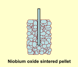
Niobium pentoxide is the inorganic compound with the formula Nb2O5. A colorless, insoluble, and fairly unreactive solid, it is the most widespread precursor for other compounds and materials containing niobium. It is predominantly used in alloying, with other specialized applications in capacitors, optical glasses, and the production of lithium niobate.

<span class="mw-page-title-main">Niobium monoxide</span> Chemical compound

Niobium monoxide is the inorganic compound with the formula NbO. It is a grey solid with metallic conductivity.

<span class="mw-page-title-main">Applications of capacitors</span> Uses of capacitors in daily life

Capacitors have many uses in electronic and electrical systems. They are so ubiquitous that it is rare that an electrical product does not include at least one for some purpose. Capacitors allow only AC signals to pass when they are charged blocking DC signals. The main components of filters are capacitors. Capacitors have the ability to connect one circuit segment to another. Capacitors are used by Dynamic Random Access Memory (DRAM) devices to represent binary information as bits.

<span class="mw-page-title-main">Tantalum capacitor</span> Type of electrolytic capacitor

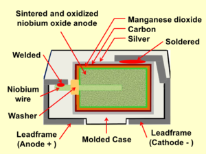
A tantalum electrolytic capacitor is an electrolytic capacitor, a passive component of electronic circuits. It consists of a pellet of porous tantalum metal as an anode, covered by an insulating oxide layer that forms the dielectric, surrounded by liquid or solid electrolyte as a cathode. Because of its very thin and relatively high permittivity dielectric layer, the tantalum capacitor distinguishes itself from other conventional and electrolytic capacitors in having high capacitance per volume and lower weight.

<span class="mw-page-title-main">Failure of electronic components</span> Ways electronic components fail and prevention measures

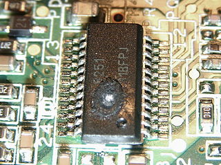
Electronic components have a wide range of failure modes. These can be classified in various ways, such as by time or cause. Failures can be caused by excess temperature, excess current or voltage, ionizing radiation, mechanical shock, stress or impact, and many other causes. In semiconductor devices, problems in the device package may cause failures due to contamination, mechanical stress of the device, or open or short circuits.

<span class="mw-page-title-main">Polymer capacitor</span> Solid conductive electrolyte

A polymer capacitor, or more accurately a polymer electrolytic capacitor, is an electrolytic capacitor (e-cap) with a solid conductive polymer electrolyte. There are four different types:

<span class="mw-page-title-main">Supercapacitor</span> Electrochemical capacitor

A supercapacitor (SC), also called an ultracapacitor, is a high-capacity capacitor, with a capacitance value much higher than solid-state capacitors but with lower voltage limits. It bridges the gap between electrolytic capacitors and rechargeable batteries. It typically stores 10 to 100 times more energy per unit volume or mass than electrolytic capacitors, can accept and deliver charge much faster than batteries, and tolerates many more charge and discharge cycles than rechargeable batteries.

Dielectric absorption is the name given to the effect by which a capacitor, that has been charged for a long time, discharges only incompletely when briefly discharged. Although an ideal capacitor would remain at zero volts after being discharged, real capacitors will develop a small voltage from time-delayed dipole discharging, a phenomenon that is also called dielectric relaxation, "soakage", or "battery action". For some dielectrics, such as many polymer films, the resulting voltage may be less than 1–2% of the original voltage, but it can be as much as 15% for electrolytic capacitors. The voltage at the terminals generated by the dielectric absorption may possibly cause problems in the function of an electronic circuit or can be a safety risk to personnel. In order to prevent shocks, most very large capacitors are shipped with shorting wires that need to be removed before they are used and/or permanently connected bleeder resistors. When disconnected at one or both ends, DC high-voltage cables can also "recharge themselves" to dangerous voltages.

<span class="mw-page-title-main">Film capacitor</span> Electrical capacitor with an insulating plastic film as the dielectric

Film capacitors, plastic film capacitors, film dielectric capacitors, or polymer film capacitors, generically called film caps as well as power film capacitors, are electrical capacitors with an insulating plastic film as the dielectric, sometimes combined with paper as carrier of the electrodes.

<span class="mw-page-title-main">KEMET Corporation</span> Industrial Manufacturer

KEMET Corporation, a subsidiary of Yageo Corporation, is an American company which manufactures a broad selection of capacitor technologies such as tantalum, aluminum, multilayer ceramic, film, paper, polymer electrolytic, and supercapacitors. KEMET also manufacturers a variety of other passive electronic components, such as AC line filters, EMI cores and filters, flex suppressors, electro-mechanical devices (relays), metal composite inductors, ferrite products, and transformers/magnetics. The product line consists of nearly 5 million distinct part configurations distinguished by various attributes, such as dielectric material, configuration, encapsulation, capacitance, voltage, performance characteristics, and packaging.

<span class="mw-page-title-main">SAL electrolytic capacitor</span> Capacitor with high capacitance in a small package

SAL electrolytic capacitors are a form of capacitor developed for high capacitance in a small package, with a long and robust service life. They are aluminum electrolytic capacitors with anodic oxidized aluminum oxide as dielectric and with the semiconducting solid manganese dioxide as electrolyte. They are made of etched and formed aluminum anodes, which are folded for the dipped pearl types or wound into a roll for the axial style. The solid manganese dioxide electrolyte is formed onto this roll in a pyrolytic process, similar to that for solid tantalum capacitors.

<span class="mw-page-title-main">Aluminum electrolytic capacitor</span> Type of capacitor

Aluminum electrolytic capacitors are polarized electrolytic capacitors whose anode electrode (+) is made of a pure aluminum foil with an etched surface. The aluminum forms a very thin insulating layer of aluminum oxide by anodization that acts as the dielectric of the capacitor. A non-solid electrolyte covers the rough surface of the oxide layer, serving in principle as the second electrode (cathode) (-) of the capacitor. A second aluminum foil called “cathode foil” contacts the electrolyte and serves as the electrical connection to the negative terminal of the capacitor.

References

  1. Shtasel, A.; Knight, H. T. (1961) [1960-11-30, 1960-07-05]. "An Investigation of Columbium as an Electrolytic Capacitor Metal" (PDF). Journal of the Electrochemical Society . Fansteel Metallurgical Corporation, North Chicago, Illinois, USA: The Electrochemical Society (ECS). 108 (4): 343–347. doi:10.1149/1.2428084. Archived (PDF) from the original on 2022-06-21. Retrieved 2022-06-21.
  2. Folster, J. H. D.; Holley, E. E.; Whitman, A. (1964-06-26). "Production engineering measure for Columbium capacitors" (report). North Adams, Massachusetts, USA: Sprague Electric Co. Archived from the original on 2022-06-21. Retrieved 2022-06-21.
  3. Tantalum-Niobium International Study Center, Tantalum and Niobium – Early History and Applications for Niobium Archived 2016-02-13 at the Wayback Machine
  4. 1 2 T. Zednicek, S. Sita, C. McCracken, W. A. Millman, J. Gill, AVX, Niobium Oxide Technology Roadmap, CARTS 2002 PDF Archived 2014-02-24 at the Wayback Machine
  5. Ch. Schnitter, A. Michaelis, U. Merker, H. C. Starck, Bayer, New Niobium Based Materials for Solid Electrolyte Capacitors, Carts 2002
  6. 1 2 J. Moore, Kemet, Nb capacitors compared to Ta capacitors a less costly alternative PDF
  7. Niobium Powder for Electrolytic Capacitor, JFE Technical Report No. 6 (October 2005) PDF
  8. 1 2 3 T. Kárník, AVX, Niobium oxide for capacitor manufacturing, Metal 2008, 2008-05-13 – 2008-05-15, PDF
  9. Y. Pozdeev-Freeman, P. Maden, Vishay, Solid-Electrolyte Niobium Capacitors Exhibit Similar Performance to Tantalum, 2002-02-01,
  10. Rutronik, Tantalum & Niobium Capacitors, Technical Standards and Benefits PDF
  11. Charles Pollack: D.R.P. 92564, filed 1896-01-14, granted 1897-05-19 D.R.P. 92564
  12. D. F. Tailor, Tantalum and Tantalum Compounds, Fansteel Inc., Encyclopedia of Chemical Technology, Vol. 19, 2nd ed. 1969 John Wiley & sons, Inc.
  13. R. L. Taylor and H. E. Haring, "A metal semi-conductor capacitor," J. Electrochem. Soc., vol. 103, p. 611, November, 1956.
  14. E. K. Reed, Jet Propulsion Laboratory, Characterization of Tantalum Polymer Capacitors, NEPP Task 1.21.5, Phase 1, FY05]
  15. D. A. McLean, F. S. Power, Proc. Inst. Radio Engrs. 44 (1956) 872
  16. Ch. Reynolds, AVX, Technical Information, Reliability Management of Tantalum Capacitors, PDF Archived 2013-08-06 at the Wayback Machine
  17. E. Vitoratos, S. Sakkopoulos, E. Dalas, N. Paliatsas, D. Karageorgopoulos, F. Petraki, S. Kennou, S. A. Choulis, Thermal degradation mechanisms of PEDOT:PSS, Organic Electronics, Volume 10, Issue 1, February 2009, Pages 61–66,
  18. Nichicon, Technical Guide, Calculation Formula of Lifetime PDF
  19. Estimating of Lifetime Fujitsu Media Devices Limited PDF Archived 2013-12-24 at the Wayback Machine
  20. NIC Technical Guide, Calculation Formula of Lifetime Archived 2013-09-15 at the Wayback Machine
  21. 1 2 T. Zednicek, AVX, A Study of Field Crystallization in Tantalum Capacitors and its effect on DCL and Reliability,
  22. 1 2 Vishay, DC Leakage Failure Mode, PDF
  23. 1 2 3 Zedníček, Tomáš; Gill, John (2003). "Voltage derating rules for solid Tantalum and Niobium capacitors" (PDF). AVX. Archived from the original (PDF) on 2013-08-06. Retrieved 2015-01-02.
  24. 1 2 3 Radovan Faltus, AVX, Advanced capacitors ensure long-term control-circuit stability, 2012-02-07, EDT
  25. "Homepage". www.iec.ch.
  26. "Welcome to the IEC Webstore". webstore.iec.ch.
  27. "Beuth Verlag – Normen, Standards & Fachliteratur kaufen | seit 1924". www.beuth.de.
  28. "G. Roos, Digi-Key, Niobium Capacitors Slow to Take Hold, 2012-11-20".

Further reading