In telecommunications, RS-232 or Recommended Standard 232 is a standard originally introduced in 1960 for serial communication transmission of data. It formally defines signals connecting between a DTE such as a computer terminal, and a DCE, such as a modem. The standard defines the electrical characteristics and timing of signals, the meaning of signals, and the physical size and pinout of connectors. The current version of the standard is TIA-232-F Interface Between Data Terminal Equipment and Data Circuit-Terminating Equipment Employing Serial Binary Data Interchange, issued in 1997. The RS-232 standard had been commonly used in computer serial ports and is still widely used in industrial communication devices.
Ethernet over twisted-pair technologies use twisted-pair cables for the physical layer of an Ethernet computer network. They are a subset of all Ethernet physical layers.

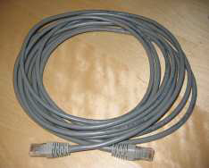
Category 5 cable (Cat 5) is a twisted pair cable for computer networks. Since 2001, the variant commonly in use is the Category 5e specification (Cat 5e). The cable standard provides performance of up to 100 MHz and is suitable for most varieties of Ethernet over twisted pair up to 2.5GBASE-T but more commonly runs at 1000BASE-T speeds. Cat 5 is also used to carry other signals such as telephone and video.

SCART is a French-originated standard and associated 21-pin connector for connecting audio-visual (AV) equipment. The name SCART comes from Syndicat des Constructeurs d'Appareils Radiorécepteurs et Téléviseurs, "Radio and Television Receiver Manufacturers' Association", the French organisation that created the connector in the mid-1970s. The related European standard EN 50049 has then been refined and published in 1978 by CENELEC, calling it péritelevision, but it is commonly called by the abbreviation péritel in French.

Components of an electrical circuit are electrically connected if an electric current can run between them through an electrical conductor. An electrical connector is an electromechanical device used to create an electrical connection between parts of an electrical circuit, or between different electrical circuits, thereby joining them into a larger circuit. Most electrical connectors have a gender – i.e. the male component, called a plug, connects to the female component, or socket. The connection may be removable, require a tool for assembly and removal, or serve as a permanent electrical joint between two points. An adapter can be used to join dissimilar connectors.

DMX512 is a standard for digital communication networks that are commonly used to control lighting and effects. It was originally intended as a standardized method for controlling stage lighting dimmers, which, prior to DMX512, had employed various incompatible proprietary protocols. It quickly became the primary method for linking controllers to dimmers and special effects devices such as fog machines and intelligent lights.
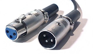
The XLR connector is a type of electrical connector primarily used in professional audio, video, and stage lighting equipment. XLR connectors are cylindrical in design, with three to seven connector pins, and are often employed for analog balanced audio interconnections, AES3 digital audio, portable intercom, DMX512 lighting control, and for low-voltage power supply. XLR connectors are included to the international standard for dimensions, IEC 61076-2-103. The XLR connector is superficially similar to the smaller DIN connector, with which it is physically incompatible.

A registered jack (RJ) is a standardized telecommunication network interface for connecting voice and data equipment to a service provided by a local exchange carrier or long distance carrier. Registration interfaces were first defined in the Universal Service Ordering Code (USOC) system of the Bell System in the United States for complying with the registration program for customer-supplied telephone equipment mandated by the Federal Communications Commission (FCC) in the 1970s. They were subsequently codified in title 47 of the Code of Federal Regulations Part 68. Registered jack connections began to see use after their invention in 1973 by Bell Labs. The specification includes physical construction, wiring, and signal semantics. Accordingly, registered jacks are primarily named by the letters RJ, followed by two digits that express the type. Additional letter suffixes indicate minor variations. For example, RJ11, RJ14, and RJ25 are the most commonly used interfaces for telephone connections for one-, two-, and three-line service, respectively. Although these standards are legal definitions in the United States, some interfaces are used worldwide.

RS-422, also known as TIA/EIA-422, is a technical standard originated by the Electronic Industries Alliance that specifies electrical characteristics of a digital signaling circuit. It was meant to be the foundation of a suite of standards that would replace the older RS-232C standard with standards that offered much higher speed, better immunity from noise, and longer cable lengths. RS-422 systems can transmit data at rates as high as 10 Mbit/s, or may be sent on cables as long as 1,200 meters (3,900 ft) at lower rates. It is closely related to RS-423, which uses the same signaling systems but on a different wiring arrangement.

The D-subminiature or D-sub is a common type of electrical connector. They are named for their characteristic D-shaped metal shield. When they were introduced, D-subs were among the smallest connectors used on computer systems.

A crossover cable connects two devices of the same type, for example DTE-DTE or DCE-DCE, usually connected asymmetrically (DTE-DCE), by a modified cable called a crosslink. Such a distinction between devices was introduced by IBM.
RS-485, also known as TIA-485(-A) or EIA-485, is a standard defining the electrical characteristics of drivers and receivers for use in serial communications systems. Electrical signaling is balanced, and multipoint systems are supported. The standard is jointly published by the Telecommunications Industry Association and Electronic Industries Alliance (TIA/EIA). Digital communications networks implementing the standard can be used effectively over long distances and in electrically noisy environments. Multiple receivers may be connected to such a network in a linear, multidrop bus. These characteristics make RS-485 useful in industrial control systems and similar applications.
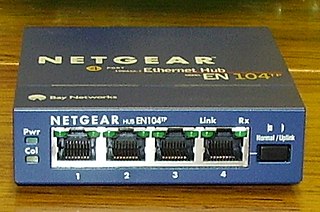
A medium dependent interface (MDI) describes the interface in a computer network from a physical layer implementation to the physical medium used to carry the transmission. Ethernet over twisted pair also defines a medium dependent interface crossover (MDI-X) interface. Auto MDI-X ports on newer network interfaces detect if the connection would require a crossover, and automatically chooses the MDI or MDI-X configuration to properly match the other end of the link.
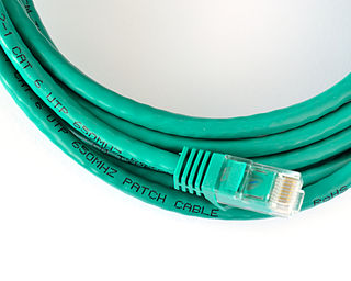
A patch cable, patch cord or patch lead is an electrical or optical cable used to connect one electronic or optical device to another for signal routing. Devices of different types are connected with patch cords.
An Ethernet crossover cable is a crossover cable for Ethernet used to connect computing devices together directly. It is most often used to connect two devices of the same type, e.g. two computers or two switches to each other. By contrast, straight through patch cables are used to connect devices of different types, such as a computer to a network switch.
A modular connector is a type of electrical connector for cords and cables of electronic devices and appliances, such as in computer networking, telecommunication equipment, and audio headsets.
RS-423, also known as TIA/EIA-423, is a technical standard originated by the Electronic Industries Alliance that specifies electrical characteristics of a digital signaling circuit. Although it was originally intended as a successor to RS-232C offering greater cable lengths, it is not widely used.
Several types of connectors for car audio systems are used.
ANSI/TIA-568 is a technical standard for commercial building cabling for telecommunications products and services. The title of the standard is Commercial Building Telecommunications Cabling Standard and is published by the Telecommunications Industry Association (TIA), a body accredited by the American National Standards Institute (ANSI).