
In telecommunications, RS-232 or Recommended Standard 232 is a standard originally introduced in 1960 for serial communication transmission of data. It formally defines signals connecting between a DTE such as a computer terminal or PC, and a DCE, such as a modem. The standard defines the electrical characteristics and timing of signals, the meaning of signals, and the physical size and pinout of connectors. The current version of the standard is TIA-232-F Interface Between Data Terminal Equipment and Data Circuit-Terminating Equipment Employing Serial Binary Data Interchange, issued in 1997. The RS-232 standard had been commonly used in computer serial ports and is still widely used in industrial communication devices.
A data circuit-terminating equipment (DCE) is a device that sits between the data terminal equipment (DTE) and a data transmission circuit. It is also called data communication(s) equipment and data carrier equipment. Usually, the DTE device is the terminal, and the DCE is a modem.

Data terminal equipment (DTE) is an end instrument that converts user information into signals or reconverts received signals. It is also called data processing terminal equipment or tail circuit. A DTE device communicates with the data circuit-terminating equipment (DCE), such as a modem. The DTE/DCE classification was introduced by IBM.

On computers, a serial port is a serial communication interface through which information transfers in or out sequentially one bit at a time. This is in contrast to a parallel port, which communicates multiple bits simultaneously in parallel. Throughout most of the history of personal computers, data has been transferred through serial ports to devices such as modems, terminals, various peripherals, and directly between computers.
In the seven-layer OSI model of computer networking, the physical layer or layer 1 is the first and lowest layer: the layer most closely associated with the physical connection between devices. The physical layer provides an electrical, mechanical, and procedural interface to the transmission medium. The shapes and properties of the electrical connectors, the frequencies to transmit on, the line code to use and similar low-level parameters, are specified by the physical layer.

Low-voltage differential signaling (LVDS), also known as TIA/EIA-644, is a technical standard that specifies electrical characteristics of a differential, serial signaling standard. LVDS operates at low power and can run at very high speeds using inexpensive twisted-pair copper cables. LVDS is a physical layer specification only; many data communication standards and applications use it and add a data link layer as defined in the OSI model on top of it.

DMX512 is a standard for digital communication networks that are commonly used to control lighting and effects. It was originally intended as a standardized method for controlling stage lighting dimmers, which, prior to DMX512, had employed various incompatible proprietary protocols. It quickly became the primary method for linking controllers to dimmers and special effects devices such as fog machines and intelligent lights.

RS-422, also known as TIA/EIA-422, is a technical standard originated by the Electronic Industries Alliance, first issued in 1975, that specifies electrical characteristics of a digital signaling circuit. It was meant to be the foundation of a suite of standards that would replace the older RS-232C standard with standards that offered much higher speed, better immunity from noise, and longer cable lengths. RS-422 systems can transmit data at rates as high as 10 Mbit/s, or may be sent on cables as long as 1,200 meters (3,900 ft) at lower rates. It is closely related to RS-423, which uses the same signaling systems but on a different wiring arrangement.

A crossover cable connects two devices of the same type, for example DTE-DTE or DCE-DCE, usually connected asymmetrically (DTE-DCE), by a modified cable called a crosslink. Such a distinction between devices was introduced by IBM.
In electronics, a pinout is a cross-reference between the contacts, or pins, of an electrical connector or electronic component, and their functions. "Pinout" now supersedes the term "basing diagram" which was the standard terminology used by the manufacturers of vacuum tubes and the RMA. The RMA started its standardization in 1934, collecting and correlating tube data for registration at what was to become the EIA. The EIA now has many sectors reporting to it and sets what is known as EIA standards where all registered pinouts and registered jacks can be found.
RS-485, also known as TIA-485(-A) or EIA-485, is a standard, originally introduced in 1983, defining the electrical characteristics of drivers and receivers for use in serial communications systems. Electrical signaling is balanced, and multipoint systems are supported. The standard is jointly published by the Telecommunications Industry Association and Electronic Industries Alliance (TIA/EIA). Digital communications networks implementing the standard can be used effectively over long distances and in electrically noisy environments. Multiple receivers may be connected to such a network in a linear, multidrop bus. These characteristics make RS-485 useful in industrial control systems and similar applications.

Differential signalling is a method for electrically transmitting information using two complementary signals. The technique sends the same electrical signal as a differential pair of signals, each in its own conductor. The pair of conductors can be wires in a twisted-pair or ribbon cable or traces on a printed circuit board.
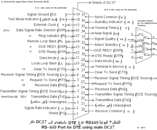
The RS-449 specification, also known as EIA-449 or TIA-449, defines the functional and mechanical characteristics of the interface between data terminal equipment, typically a computer, and data communications equipment, typically a modem or terminal server. The full title of the standard is EIA-449 General Purpose 37-Position and 9-Position Interface for Data Terminal Equipment and Data Circuit-Terminating Equipment Employing Serial Binary Data Interchange.

Currently known as TIA-530-A, but often called EIA-530, or RS-530, is a balanced serial interface standard that generally uses a 25-pin connector, originally created by the Telecommunications Industry Association.

The Modified Modular Jack (MMJ) is a small form-factor serial port connector developed by Digital Equipment Corporation (DEC). It uses a modified version of the 6P6C modular connector with the latch displaced off-center so standard modular connectors found on Ethernet cables or phone jacks cannot accidentally be plugged in. MMJ connections are used on Digital minicomputers, such as the PDP-11, VAX and Alpha systems, and to connect terminals, printers, and serial console servers.

A modular connector is a type of electrical connector for cords and cables of electronic devices and appliances, such as in computer networking, telecommunication equipment, and audio headsets.

The MAX232 is an integrated circuit by Maxim Integrated Products, now a subsidiary of Analog Devices, that converts signals from a TIA-232 (RS-232) serial port to signals suitable for use in TTL-compatible digital logic circuits. The MAX232 is a dual transmitter / dual receiver that typically is used to convert the RX, TX, CTS, RTS signals.
ANSI/TIA-568 is a technical standard for commercial building cabling for telecommunications products and services. The title of the standard is Commercial Building Telecommunications Cabling Standard and is published by the Telecommunications Industry Association (TIA), a body accredited by the American National Standards Institute (ANSI).
