AES3

Last updated

AES3 is a standard for the exchange of digital audio signals between professional audio devices. An AES3 signal can carry two channels of pulse-code-modulated digital audio over several transmission media including balanced lines, unbalanced lines, and optical fiber. [1]

Contents

AES3 was jointly developed by the Audio Engineering Society (AES) and the European Broadcasting Union (EBU) and so is also known as AES/EBU. The standard was first published in 1985 and was revised in 1992 and 2003. AES3 has been incorporated into the International Electrotechnical Commission's standard IEC 60958, and is available in a consumer-grade variant known as S/PDIF.

History and development

The development of standards for digital audio interconnect for both professional and domestic audio equipment, began in the late 1970s [2] in a joint effort between the Audio Engineering Society and the European Broadcasting Union, and culminated in the publishing of AES3 in 1985. The AES3 standard has been revised in 1992 and 2003 and is published in AES and EBU versions. [1] Early on, the standard was frequently known as AES/EBU.

Variants using different physical connections are specified in IEC 60958. These are essentially consumer versions of AES3 for use within the domestic high fidelity environment using connectors more commonly found in the consumer market. These variants are commonly known as S/PDIF.

IEC 60958

IEC 60958 (formerly IEC 958) is the International Electrotechnical Commission's standard on digital audio interfaces. It reproduces the AES3 professional digital audio interconnect standard and the consumer version of the same, S/PDIF.

The standard consists of several parts:

AES-2id

AES-2id is an AES information document published by the Audio Engineering Society [3] for digital audio engineering—Guidelines for the use of the AES3 interface. This document provides guidelines for the use of AES3, AES Recommended Practice for Digital Audio Engineering, Serial transmission format for two-channel linearly represented digital audio data. This document also covers the description of related standards used in conjunction with AES3 such as AES11. The full details of AES-2id can be studied in the standards section of the Audio Engineering Society web site [4] by downloading copies of the AES-2id document as a PDF file.

Hardware connections

The AES3 standard parallels part 4 of the international standard IEC 60958. Of the physical interconnection types defined by IEC 60958, two are in common use.

IEC 60958 type I

XLR connectors, used for IEC 60958 type I connections. Xlr-connectors.jpg
XLR connectors, used for IEC 60958 type I connections.

Type I connections use balanced, three-conductor, 110-ohm twisted pair cabling with XLR connectors. Type I connections are most often used in professional installations and are considered the standard connector for AES3. The hardware interface is usually implemented using RS-422 line drivers and receivers.

Type I connector ends
Cable endDevice end
InputXLR male plugXLR female jack
OutputXLR female plugXLR male jack

IEC 60958 type II

IEC 60958 Type II defines an unbalanced electrical or optical interface for consumer electronics applications. The precursor of the IEC 60958 Type II specification was the Sony/Philips Digital Interface, or S/PDIF. Both were based on the original AES/EBU work. S/PDIF and AES3 are interchangeable at the protocol level, but at the physical level, they specify different electrical signalling levels and impedances, which may be significant in some applications.

BNC Connector

BNC connector, used for AES-3id connections. BNC connector 20050720 001.jpg
BNC connector, used for AES-3id connections.

AES/EBU signals can also be run using unbalanced BNC connectors a with a 75-ohm coaxial cable. The unbalanced version has a very long transmission distance as opposed to the 150 meters maximum for the balanced version. [5] The AES-3id standard defines a 75-ohm BNC electrical variant of AES3. This uses the same cabling, patching and infrastructure as analogue or digital video, and is thus common in the broadcast industry.

Protocol

Simple representation of the protocol for both AES3 and S/PDIF SPDIF AES EBU protocol colored.svg
Simple representation of the protocol for both AES3 and S/PDIF
The low-level protocol for data transmission in AES3 and S/PDIF is largely identical, and the following discussion applies for S/PDIF, except as noted.

AES3 was designed primarily to support stereo PCM encoded audio in either DAT format at 48 kHz or CD format at 44.1 kHz. No attempt was made to use a carrier able to support both rates; instead, AES3 allows the data to be run at any rate, and encoding the clock and the data together using biphase mark code (BMC).

Each bit occupies one time slot. Each audio sample (of up to 24 bits) is combined with four flag bits and a synchronisation preamble which is four time slots long to make a subframe of 32 time slots. The 32 time slots of each subframe are assigned as follows:

AES3 subframe
Time slotNameDescription
0–3PreambleA synchronisation preamble (biphase mark code violation) for audio blocks, frames, and subframes.
4–7Auxiliary sample (optional)A low-quality auxiliary channel used as specified in the channel status word, notably for producer talkback or recording studio-to-studio communication.
8–27, or 4–27Audio sampleOne sample stored with most significant bit (MSB) last. If the auxiliary sample is used, bits 4–7 are not included. Data with smaller sample bit depths always have MSB at bit 27 and are zero-extended towards the least significant bit (LSB).
28Validity (V)Unset if the audio data are correct and suitable for D/A conversion. During the presence of defective samples, the receiving equipment may be instructed to mute its output. It is used by most CD players to indicate that concealment rather than error correction is taking place.
29User data (U)Forms a serial data stream for each channel (with 1 bit per frame), with a format specified in the channel status word.
30Channel status (C)Bits from each frame of an audio block are collated giving a 192-bit channel status word. Its structure depends on whether AES3 or S/PDIF is used.
31Parity (P) Even parity bit for detection of errors in data transmission. Excludes preamble; Bits 4–31 have an even number of ones.

Two subframes (A and B, normally used for left and right audio channels) make a frame. Frames contain 64 bit periods and are produced once per audio sample period. At the highest level, each 192 consecutive frames are grouped into an audio block. While samples repeat each frame time, metadata is only transmitted once per audio block. At 48 kHz sample rate, there are 250 audio blocks per second, and 3,072,000 time slots per second supported by a 6.144 MHz biphase clock. [6]

Synchronisation preamble

The synchronisation preamble is a specially coded preamble that identifies the subframe and its position within the audio block. Preambles are not normal BMC-encoded data bits, although they do still have zero DC bias.

Three preambles are possible:

The three preambles are called X, Y, Z in the AES3 standard; and M, W, B in IEC 958 (an AES extension).

The 8-bit preambles are transmitted in the time allocated to the first four time slots of each subframe (time slots 0 to 3). Any of the three marks the beginning of a subframe. X or Z marks the beginning of a frame, and Z marks the beginning of an audio block.

 | 0 | 1 | 2 | 3 |  | 0 | 1 | 2 | 3 | Time slots   _____       _            _____   _  /     \_____/ \_/  \_____/     \_/ \ Preamble X   _____     _              ___   ___  /     \___/ \___/  \_____/   \_/   \ Preamble Y   _____   _                _   _____  /     \_/ \_____/  \_____/ \_/     \ Preamble Z   ___     ___            ___     ___   /   \___/   \___/  \___/   \___/   \ All 0 bits BMC encoded   _   _   _   _        _   _   _   _  / \_/ \_/ \_/ \_/  \_/ \_/ \_/ \_/ \ All 1 bits BMC encoded    | 0 | 1 | 2 | 3 |  | 0 | 1 | 2 | 3 | Time slots 

In two-channel AES3, the preambles form a pattern of ZYXYXYXY..., but it is straightforward to extend this structure to additional channels (more subframes per frame), each with a Y preamble, as is done in the MADI protocol.

Channel status word

There is one channel status bit in each subframe, a total of 192 bits or 24 bytes for each channel in each block. Between the AES3 and S/PDIF standards, the contents of the 192-bit channel status word differ significantly, although they agree that the first channel status bit distinguishes between the two. In the case of AES3, the standard describes, in detail, the function of each bit. [1]

Embedded timecode

SMPTE timecode data can be embedded within AES3 signals. It can be used for synchronization and for logging and identifying audio content. It is embedded as a 32-bit binary word in bytes 18 to 21 of the channel status data. [8]

The AES11 standard provides information on the synchronization of digital audio structures. [9]

the AES52 standard describes how to insert unique identifiers into an AES3 bit stream. [10]

SMPTE 2110

SMPTE 2110-31 defines how to encapsulate an AES3 data stream in Real-time Transport Protocol packets for transmission over an IP network using the SMPTE 2110 IP based multicast framework. [11]

SMPTE 302M

SMPTE 302M-2007 defines how to encapsulate an AES3 data stream in an MPEG transport stream for television applications. [12]

Other formats

AES3 digital audio format can also be carried over an Asynchronous Transfer Mode network. The standard for packing AES3 frames into ATM cells is AES47.

See also

Notes

  1. Exactly 24h51m18.485333s
  2. Generator polynomial is x8+x4+x3+x2+1, preset to 1.

Related Research Articles

<span class="mw-page-title-main">MPEG-2</span> Video encoding standard

MPEG-2 is a standard for "the generic coding of moving pictures and associated audio information". It describes a combination of lossy video compression and lossy audio data compression methods, which permit storage and transmission of movies using currently available storage media and transmission bandwidth. While MPEG-2 is not as efficient as newer standards such as H.264/AVC and H.265/HEVC, backwards compatibility with existing hardware and software means it is still widely used, for example in over-the-air digital television broadcasting and in the DVD-Video standard.

<span class="mw-page-title-main">Digital audio</span> Technology that records, stores, and reproduces sound

Digital audio is a representation of sound recorded in, or converted into, digital form. In digital audio, the sound wave of the audio signal is typically encoded as numerical samples in a continuous sequence. For example, in CD audio, samples are taken 44,100 times per second, each with 16-bit sample depth. Digital audio is also the name for the entire technology of sound recording and reproduction using audio signals that have been encoded in digital form. Following significant advances in digital audio technology during the 1970s and 1980s, it gradually replaced analog audio technology in many areas of audio engineering, record production and telecommunications in the 1990s and 2000s.

<span class="mw-page-title-main">S/PDIF</span> Standardized digital audio interface

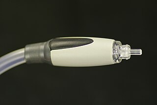
S/PDIF is a type of digital audio interface used in consumer audio equipment to output audio over relatively short distances. The signal is transmitted over either a coaxial cable or a fiber-optic cable with TOSLINK connectors. S/PDIF interconnects components in home theaters and other digital high-fidelity systems.

<span class="mw-page-title-main">SMPTE timecode</span> Standards to label individual frames of video or film with a timestamp

SMPTE timecode is a set of cooperating standards to label individual frames of video or film with a timecode. The system is defined by the Society of Motion Picture and Television Engineers in the SMPTE 12M specification. SMPTE revised the standard in 2008, turning it into a two-part document: SMPTE 12M-1 and SMPTE 12M-2, including new explanations and clarifications.

AC'97 is an audio codec standard developed by Intel Architecture Labs and various codec manufacturers in 1997. The standard was used in motherboards, modems, and sound cards.

<span class="mw-page-title-main">Serial digital interface</span> Family of digital video interfaces

Serial digital interface (SDI) is a family of digital video interfaces first standardized by SMPTE in 1989. For example, ITU-R BT.656 and SMPTE 259M define digital video interfaces used for broadcast-grade video. A related standard, known as high-definition serial digital interface (HD-SDI), is standardized in SMPTE 292M; this provides a nominal data rate of 1.485 Gbit/s.

The Digital Audio Stationary Head or DASH standard is a reel-to-reel, digital audio tape format introduced by Sony in early 1982 for high-quality multitrack studio recording and mastering, as an alternative to analog recording methods. DASH is capable of recording two channels of audio on a quarter-inch tape, and 24 or 48 tracks on 12-inch-wide (13 mm) tape on open reels of up to 14 inches. The data is recorded on the tape linearly, with a stationary recording head, as opposed to the DAT format, where data is recorded helically with a rotating head, in the same manner as a VCR. The audio data is encoded as linear PCM and boasts strong cyclic redundancy check (CRC) error correction, allowing the tape to be physically edited with a razor blade as analog tape would, e.g. by cutting and splicing, and played back with no loss of signal. In a two-track DASH recorder, the digital data is recorded onto the tape across nine data tracks: eight for the digital audio data and one for the CRC data; there is also provision for two linear analog cue tracks and one additional linear analog track dedicated to recording time code.

I²S, is an electrical serial bus interface standard used for connecting digital audio devices together. It is used to communicate PCM audio data between integrated circuits in an electronic device. The I²S bus separates clock and serial data signals, resulting in simpler receivers than those required for asynchronous communications systems that need to recover the clock from the data stream. Alternatively I²S is spelled I2S or IIS. Despite the similar name, I²S is unrelated to the bidirectional I²C (IIC) bus.

<span class="mw-page-title-main">HDCAM</span> Magnetic tape-based videocassette format for HD video

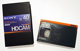
HDCAM is a high-definition video digital recording videocassette version of Digital Betacam introduced in 1997 that uses an 8-bit discrete cosine transform (DCT) compressed 3:1:1 recording, in 1080i-compatible down-sampled resolution of 1440×1080, and adding 24p and 23.976 progressive segmented frame (PsF) modes to later models. The HDCAM codec uses rectangular pixels and as such the recorded 1440×1080 content is upsampled to 1920×1080 on playback. The recorded video bit rate is 144 Mbit/s. Audio is also similar, with four channels of AES3 20-bit, 48 kHz digital audio. Like Betacam, HDCAM tapes were produced in small and large cassette sizes; the small cassette uses the same form factor as the original Betamax. The main competitor to HDCAM was the DVCPRO HD format offered by Panasonic, which uses a similar compression scheme and bit rates ranging from 40 Mbit/s to 100 Mbit/s depending on frame rate.

AES47 is a standard which describes a method for transporting AES3 professional digital audio streams over Asynchronous Transfer Mode (ATM) networks.

Dolby Digital Plus, also known as Enhanced AC-3, is a digital audio compression scheme developed by Dolby Labs for the transport and storage of multi-channel digital audio. It is a successor to Dolby Digital (AC-3), and has a number of improvements over that codec, including support for a wider range of data rates, an increased channel count, and multi-program support, as well as additional tools (algorithms) for representing compressed data and counteracting artifacts. Whereas Dolby Digital (AC-3) supports up to five full-bandwidth audio channels at a maximum bitrate of 640 kbit/s, E-AC-3 supports up to 15 full-bandwidth audio channels at a maximum bitrate of 6.144 Mbit/s.

SMPTE 292 is a digital video transmission line standard published by the Society of Motion Picture and Television Engineers (SMPTE). This technical standard is usually referred to as HD-SDI; it is part of a family of standards that define a Serial Digital Interface based on a coaxial cable, intended to be used for transport of uncompressed digital video and audio in a television studio environment.

Ancillary data is data that has been added to given data and uses the same form of transport. Common examples are cover art images for media files or streams, or digital data added to radio or television broadcasts.

AES52 is a standard first published by the Audio Engineering Society in March 2006 that specifies the insertion of unique identifiers into the AES3 digital audio transport structure.

<span class="mw-page-title-main">MADI</span> Multichannel digital audio interface

Multichannel Audio Digital Interface (MADI) standardized as AES10 by the Audio Engineering Society (AES) defines the data format and electrical characteristics of an interface that carries multiple channels of digital audio. The AES first documented the MADI standard in AES10-1991 and updated it in AES10-2003 and AES10-2008. The MADI standard includes a bit-level description and has features in common with the two-channel AES3 interface.

McASP is an acronym for Multichannel Audio Serial Port, a communication peripheral found in Texas Instruments family of digital signal processors (DSPs) and Microcontroller Units (MCUs).
The McASP functions as a general-purpose audio serial port optimized for the needs of multichannel audio applications. Depending on the implementation, the McASP may be useful for time-division multiplexed (TDM) stream, Inter-Integrated Sound (I2S) protocols, and intercomponent digital audio interface transmission (DIT). However, some implementations are limited to supporting just the Inter-Integrated Sound (I2S) protocol.
The McASP consists of transmit and receive sections that may operate synchronized, or completely independently with separate master clocks, bit clocks, and frame syncs, and using different transmit modes with different bit-stream formats. The McASP module also includes up to 16 serializers that can be individually enabled to either transmit or receive. In addition, all of the McASP pins can be configured as general-purpose input/output (GPIO) pins.

The ADAT Lightpipe, officially the ADAT Optical Interface, is a standard for the transfer of digital audio between equipment. It was originally developed by Alesis but has since become widely accepted, with many third party hardware manufacturers including Lightpipe interfaces on their equipment. The protocol has become so popular that the term ADAT is now often used to refer to the transfer standard rather than to the Alesis Digital Audio Tape itself.

The Serial Low-power Inter-chip Media Bus (SLIMbus) is a standard interface between baseband or application processors and peripheral components in mobile terminals. It was developed within the MIPI Alliance, founded by ARM, Nokia, STMicroelectronics and Texas Instruments. The interface supports many digital audio components simultaneously, and carries multiple digital audio data streams at differing sample rates and bit widths.

AES67 is a technical standard for audio over IP and audio over Ethernet (AoE) interoperability. The standard was developed by the Audio Engineering Society and first published in September 2013. It is a layer 3 protocol suite based on existing standards and is designed to allow interoperability between various IP-based audio networking systems such as RAVENNA, Livewire, Q-LAN and Dante.

AES50 is an Audio over Ethernet protocol for multichannel digital audio. It is defined by the AES50-2011 standard for High-resolution multi-channel audio interconnection (HRMAI).

References

  1. 1 2 3 "Specification of the AES/EBU digital audio interface (The AES/EBU interface)" (PDF). European Broadcast Union. 2004. Retrieved 2014-01-07.
  2. "About AES Standards". Audio Engineering Society. Retrieved 2014-01-07. In 1977, stimulated by the growing need for standards in digital audio, the AES Digital Audio Standards Committee was formed.
  3. AES Official Site
  4. Standards web site
  5. John Emmett (1995), Engineering Guidelines: the EBU/AES Digital Audio Interface (PDF), European Broadcasting Union
  6. Robin, Michael (1 September 2004). "The AES/EBU digital audio signal distribution standard". Broadcastengineering.com. Archived from the original on 2012-07-09. Retrieved 2012-05-13.
  7. "Specification of the AES/EBU digital audio interface (The AES/EBU interface)" (PDF). European Broadcast Union. 2004. p. 12. Retrieved 2014-01-07. Bytes 18 to 21, Bits 0 to 7: Time of day sample address code. Value (each Byte): 32-bit binary value representing the first sample of current block. LSBs are transmitted first. Default value shall be logic "0". Note: This is the time-of-day laid down during the source encoding of the signal and shall remain unchanged during subsequent operations. A value of all zeros for the binary sample address code shall, for the purposes of transcoding to real time, or to time codes in particular, be taken as midnight (i.e., 00 h, 00 mm, 00 s, 00 frame). Transcoding of the binary number to any conventional time code requires accurate sampling frequency information to provide the sample accurate time.
  8. Ratcliff, John (1999). Timecode: A user's guide. Focal Press. pp. 226, 228. ISBN   0-240-51539-0.
  9. AES11-2009 (r2019): AES recommended practice for digital audio engineering - Synchronization of digital audio equipment in studio operations, Audio Engineering Society, 2009
  10. AES52-2006 (r2017): AES standard for digital audio engineering - Insertion of unique identifiers into the AES3 transport stream, Audio Engineering Society, 2006
  11. "ST 2110-31:2018 - SMPTE Standard - Professional Media Over Managed IP Networks: AES3 Transparent Transport", St 2110-31:2018: 1–12, August 2018, doi:10.5594/SMPTE.ST2110-31.2018, ISBN   978-1-68303-151-2
  12. "ST 302:2007 - SMPTE Standard - For Television — Mapping of AES3 Data into an MPEG-2 Transport Stream", St 302:2007: 1–9, October 2007, doi:10.5594/SMPTE.ST302.2007, ISBN   978-1-68303-151-2

Further reading