Reflector sight

Last updated
A view through the Mark III Free Gun Reflector Sight, first produced in 1943, used on British army guns, naval guns, and as a pilot sight and a defensive gun sight on aircraft. The reticle image in this sight is produced by an optical collimator bounced off a beam splitter. The dot remains on the target even though the viewer's head is moved side to side Mark III free gun reflector sight mk 9 variant reflex sight animation.gif
A view through the Mark III Free Gun Reflector Sight, first produced in 1943, used on British army guns, naval guns, and as a pilot sight and a defensive gun sight on aircraft. The reticle image in this sight is produced by an optical collimator bounced off a beam splitter. The dot remains on the target even though the viewer's head is moved side to side

A reflector sight or reflex sight is an optical sight that allows the user to look through a partially reflecting glass element and see an illuminated projection of an aiming point or some other image superimposed on the field of view. [1] [2] These sights work on the simple optical principle that anything at the focus of a lens or curved mirror (such as an illuminated reticle) will appear to be sitting in front of the viewer at infinity. Reflector sights employ some sort of "reflector" to allow the viewer to see the infinity image and the field of view at the same time, either by bouncing the image created by lens off a slanted glass plate, or by using a mostly clear curved glass reflector that images the reticle while the viewer looks through the reflector. Since the reticle is at infinity it stays in alignment with the device to which the sight is attached regardless of the viewer's eye position, removing most of the parallax and other sighting errors found in simple sighting devices.

Contents

Since their invention in 1900, reflector sights have come to be used as gun sights on various weapons. They were used on fighter aircraft, in a limited capacity in World War I, widely used in World War II, and still used as the base component in many types of modern head-up displays. They have been used in other types of (usually large) weapons as well, such as anti-aircraft gun sights, anti-tank gun sights, and any other role where the operator had to engage fast moving targets over a wide field of view, and the sight itself could be supplied with sufficient electrical power to function. There was some limited use of the sight on small arms after World War II, but the sight came into widespread use during the late 1970s with the invention of the red dot sight. This sight uses a red light-emitting diode (LED) as its illumination source, making a durable, dependable sight with an extremely long illumination run time.

Other applications of reflector sights include sights on surveying equipment, optical telescope pointing aids, and camera viewfinders.

Design

Diagram of three types of reflector sights. The top uses a collimating lens (CL) and a beam splitter (B) to create a virtual image at infinity (V) of a reticle (R). The bottom two use half silvered curved mirrors (CM) as the collimating optics Reflector reflex sight diagram 3.png
Diagram of three types of reflector sights. The top uses a collimating lens (CL) and a beam splitter (B) to create a virtual image at infinity (V) of a reticle (R). The bottom two use half silvered curved mirrors (CM) as the collimating optics

Reflector sights work by using a lens or an image-forming curved mirror with a luminous or reflective overlay image or reticle at its focus, creating an optical collimator that produces a virtual image of that reticle. The image is reflected off some form of angled beam splitter or the partially silvered collimating curved mirror itself so that the observer (looking through the beam splitter or mirror) will see the image at the focus of the collimating optics superimposed in the sight's field of view in focus at ranges up to infinity. Since the optical collimator produces a reticle image made up of collimated light, light that is nearly parallel, the light making up that image is theoretically perfectly parallel with the axis of the device or gun barrel it is aligned with, i.e. with no parallax at infinity. The collimated reticle image can also be seen at any eye position in the cylindrical volume of collimated light created by the sight behind the optical window. [2] But this also means, for targets closer than infinity, sighting towards the edge of the optical window can make the reticle move in relation to the target since the observer is sighting down a parallel light bundle at the edge. Eye movement perpendicular to the device's optical axis will make the reticle image move in exact relationship to eye position in the cylindrical column of light created by the collimating optics. [3] [4]

A common type (used in applications such as aircraft gun sights) uses a collimating lens and a beam splitter. This type tends to be bulky since it requires at least two optical components, the lens and the beam splitter/glass plate. The reticle collimation optics are situated at 90° to the optical path making lighting difficult, usually needing additional electric illumination, condensing lenses, etc. A more compact type replaces the lens/beam splitter configuration with a half silvered or dichroic curved collimating mirror set at an angle that performs both tasks of focusing and combining the image of an offset reticle. This type is most often seen as the red dot type used on small arms. It is also possible to place the reticle between the viewer and the curved mirror at the mirror's focus. The reticle itself is too close to the eye to be in focus but the curved mirror presents the viewer with an image of the reticle at infinity. This type was invented by Dutch optical engineer Lieuwe van Albada in 1932, [5] originally as a camera viewfinder, and was also used as a gunsight on World War II bazookas: the US M9 and M9A1 "Bazooka" featured the D7161556 folding "Reflecting Sight Assembly". [6]

The viewing portion of a reflector sight does not use any refractive optical elements, it is simply a projected reticle bounced off a beam splitter or curved mirror right into the users eye. This gives it the defining characteristics of not needing considerable experience and skill to use, as opposed to simple mechanical sights such as iron sights. A reflector sight also does not have the field of view and eye relief problems of sights based on optical telescopes: depending on design constraints their field of view is the user's naked eye field of view, and their non-focusing collimated nature means they do not have the optical telescopes constraint of eye relief. Reflector sights can be combined with telescopes, usually by placing the telescope directly behind the sight so it can view the projected reticle creating a telescopic sight, but this re-introduces the problems of narrow field of view and limited eye relief. [4] The primary drawback of reflector sight is that they need some way to illuminate the reticle to function. Reticles illuminated by ambient light are hard to use in low light situations, and sights with electrical illumination stop functioning altogether if that system fails. [7]

History

1901 diagram of a version of Howard Grubb's collimating reflector sight designed to make a compact version suitable for firearms and small devices. Ambient lighting of the reticle was improved by placing it facing up and bouncing it off a relay mirror then off a concave collimating mirror Reflector reflex sight howard grubb 1901.png
1901 diagram of a version of Howard Grubb's collimating reflector sight designed to make a compact version suitable for firearms and small devices. Ambient lighting of the reticle was improved by placing it facing up and bouncing it off a relay mirror then off a concave collimating mirror
Prototype of the Grubb reflector sight attached to a rifle Howard Grubb Reflexvisier 2.jpg
Prototype of the Grubb reflector sight attached to a rifle

The idea of a reflector sight originated in 1900 with Irish optical designer and telescope maker Howard Grubb in patent No.12108. [8] [9] Grubb conceived of his "Gun Sight for large and small Ordnance" as a better alternative to the difficult to use iron sight while avoiding the telescopic sight's limited field of view, greater apparent target speed, parallax errors, and the danger of keeping the eye against an eye stop. In the 1901 the Scientific Transactions of the Royal Dublin Society he described his invention as: [10]

It would be possible to conceive an arrangement by which a fine beam of light like that from a search light would be projected from a gun in the direction of its axis and so adjusted as to correspond with the line of fire so that wherever the beam of light impinged upon an object the shot would hit. This arrangement would be of course equally impracticable for obvious reasons but it is instanced to show that a beam of light has the necessary qualifications for our purposes.

Now the sight which forms the subject of this Paper attains a similar result not by projecting an actual spot of light or an image on the object but by projecting what is called in optical language a virtual image upon it.

It was noted soon after its invention that the sight could be a good alternative to iron sights and also had uses in surveying and measuring equipment. [11] The reflector sight was first used on German fighter aircraft in 1918 [12] [13] and widely adopted on all kinds of fighter and bomber aircraft in the 1930s. By World War II the reflector sight was being used on many types of weapons besides aircraft, including anti-aircraft guns, naval guns, anti-tank weapons, and many other weapons where the user needed the simplicity and quick target acquisition nature of the sight. Through its development in the 1930s and into World War II the sight was also being referred to in some applications by the abbreviation "reflex sight". [14] [15]

Weapon sights

German paratrooper looks through the reflector sight of the Flakvisier 40 gunsight on a FlaK 38 anti-aircraft gun (1944), one of the more sophisticated sights at the time Bundesarchiv Bild 101I-584-2165-12, Frankreich, Fallschirmjager an Geschutz.jpg
German paratrooper looks through the reflector sight of the Flakvisier 40 gunsight on a FlaK 38 anti-aircraft gun (1944), one of the more sophisticated sights at the time

Reflector sights were invented as an improved gun-sight and since their invention they have been adapted to many types of weapons. When used with different types of guns, reflector sights are considered an improvement over simple iron sights (sights composed of two spaced metal aiming points that have to be aligned). [16] Iron sights take considerable experience and skill in the user who has to hold a proper eye position and focus exclusively on the front sight, keeping it centered on the (unfocused) rear sight, while keeping the whole centered on a target at different distances, requiring alignment of all three planes of focus to achieve a hit. [17] [18] The reflector sight's single, parallax-free virtual image, in focus with the target, removes this aiming problem, helping poor, average, and expert shooters alike.

Since the collimated image produced by the sight is only truly parallax free at infinity, the sight has an error circle equal to the diameter of the collimating optics for any target at a finite distance. Depending on the eye position behind the sight and the closeness of the target this induces some aiming error. [3] For larger targets at a distance (given the non-magnifying, quick target acquisitions nature of the sight) this aiming error is considered trivial. [4] On small arms aimed at close targets this is compensated for by keeping the reticle in the middle of the optical window (sighting down its optical axis). [19] Some manufacturers of small arms sights also make models with the optical collimator set at a finite distance. This gives the sight parallax due to eye movement the size of the optical window at close range which diminishes to a minimal size at the set distance (somewhere around a desired target range of 25–50 yd (23–46 m)). [3]

Compared to standard telescopic sights, a reflector sight can be held at any distance from the eye (does not require a designed eye relief), and at almost any angle, without distorting the image of the target or reticle. They are often used with both eyes open (the brain will tend to automatically superimpose the illuminated reticle image coming from the dominant eye onto the other eye's unobstructed view), giving the shooter normal depth perception and full field of view. Since reflector sights are not dependent on eye relief, they can theoretically be placed in any mechanically-convenient mounting position on a weapon.

Aircraft

Longitudinal cross-section of a basic reflector sight for pre-WWII German fighter planes (1937 German Revi C12/A) Revi C12-A.jpg
Longitudinal cross-section of a basic reflector sight for pre-WWII German fighter planes (1937 German Revi C12/A)

The earliest record of the reflector sight being used with fighter aircraft was in 1918. The optical firm of Optische Anstalt Oigee of Berlin, working from the Grubb patents, developed two versions what came to be known as the Oigee Reflector Sight. Both used a 45 degree angle glass beam splitter and electrical illumination and were used to aim the plane's machine guns. One version was used in operational trials on the biplane Albatros D.Va and triplane Fokker Dr.1 fighters. [13] There was some interest in this sight after World War I but reflector sights in general were not widely adopted for fighter and bomber aircraft until the 1930s, first by the French, then by most other major airforces. [20] These sights were not only used for aiming fighter aircraft, they were used with aircraft defensive guns and in bombsights.

Reflector sights as aircraft gun-sights have many advantages. The pilot/gunner need not position their head to align the sight line precisely as they did in two-point mechanical sights, head position is only limited to that determined by the optics in the collimator, mostly by the diameter of the collimator lens. The sight does not interfere with the overall view, particularly when the collimator light is turned off. Both eyes may be used simultaneously for sighting.

HUD inside the cockpit of a fighter jet Hud on the cat.jpg
HUD inside the cockpit of a fighter jet

The optical nature of the reflector sight meant it was possible to feed other information into field of view, such as modifications of the aiming point due to deflection determined by input from a gyroscope. [21] 1939 saw the development by the British of the first of these gyro gunsights, reflector sights adjusted by gyroscope for the aircraft's speed and rate of turn, enabling the display of a lead-adjusted sighting reticle that lagged the actual "boresight" of the weapon(s), allowing the boresight to lead the target in a turn by the proper amount for an effective strike [21]

As reflector sight designs advanced after World War II, giving the pilot more and more information, they eventually evolved into the head-up display (HUD). [22] The illuminated reticle was eventually replaced by a video screen at the focus of the collimating optics that not only gave a sighting point and information from a lead-finding computer and radar, but also various aircraft indicators (such as an artificial horizon, compass, altitude and airspeed indicators), facilitating the visual tracking of targets or the transition from instrument to visual methods during landings.

Firearms

A US Marine looking through an ITL MARS reflex sight on his M16A4 rifle INDIA5.jpg
A US Marine looking through an ITL MARS reflex sight on his M16A4 rifle

The idea of attaching a reflector sight to a firearm has been around since its invention in 1900. [10] Soon after World War II, models appeared for rifles and shotguns including the Nydar shotgun sight (1945), [23] which used a curved semi-reflective mirror to reflect an ambient lit reticle, [24] and the Giese electric gunsight (1947), which had a battery-powered illuminated reticle. [25] Later types included the Qwik-Point (1970) and the Thompson Insta-Sight. Both were beam-splitter type reflector sights that used ambient light: illuminating a green crosshair in the Insta-Sight, and a red plastic rod "light pipe" that produced a red aiming spot reticle in the Qwik-Point. [26]

A view through a Tasco ProPoint red dot sight Tasco PDP2.jpg
A view through a Tasco ProPoint red dot sight

The mid- to late 1970s saw the introduction of what are usually referred to as red dot sights, a type that gives the user a simple bright red dot as an aiming point. [27] The typical configuration for this sight is a compact curved mirror reflector design with a red light-emitting diode (LED) at its focus. Using an LED as a reticle is an innovation that greatly improves the reliability and general usefulness of the sight: there is no need for other optical elements to focus light behind a reticle; the mirror can use a dichroic coating to reflect just the red spectrum, passing through most other light; and the LED itself is solid state and consumes very little power, allowing battery-powered sights to run for hundreds and even tens of thousands of hours.

Reflector sights for military firearms (usually referred to as reflex sights) took a long time to be adopted. The US House Committee on Armed Services noted as far back as 1975 on the suitability of the use of reflex sight for the M16 rifle, [28] but the US military did not widely introduce reflector sights until the early 2000s with the Aimpoint CompM2 red dot sight, designated the "M68 Close Combat Optic".

Reticle types

Many reticle illumination and pattern options are available. Common light sources used in firearm reflector sights include battery powered lights, fiber optic light collectors, and even tritium capsules. Some sights are specifically designed to be visible when viewed through night vision devices. The color of a sight reticle is often red or amber for visibility against most backgrounds. Some sights use a chevron or triangular pattern instead, to aid precision aiming and range estimation, and still others provide selectable patterns.

Sights that use dot reticles are almost invariably measured in minutes of arc, sometimes called "minutes of angle" or "moa". Moa is a convenient measure for shooters using Imperial or US customary units, since 1 moa subtends approximately 1 in (25 mm) at a distance of 100 yd (91 m), which makes moa a convenient unit to use in ballistics calculations. A 5 moa (1.5 milliradian) dot is small enough not to obscure most targets, and large enough to quickly acquire a proper "sight picture". For many types of action shooting, a larger dot has traditionally been preferred; 7, 10, 15 or even 20 moa (2, 3, 4.5 or 6 mil) have been used; often these will be combined with horizontal and/or vertical lines to provide a level reference.

Most sights have either active or passive adjustments for the reticle brightness, which help the shooter adapt to different lighting conditions. A very dim reticle will help prevent loss of night vision in low-light conditions, while a brighter reticle will display more clearly in full sunlight.

Modern optical reflector sights designed for firearms and other uses fall into two housing-configurations: "tubed" and "open". [29]

Other uses

The Telrad, a reflector sight for astronomical telescopes introduced in the late 1970s Telrad hinten.jpg
The Telrad, a reflector sight for astronomical telescopes introduced in the late 1970s

Reflector sights have been used over the years in nautical navigation devices and surveying equipment. Albada type sights were used on early large format cameras, "Point and shoot" type cameras, and on simple disposable cameras. [30]

These sights are also used on astronomical telescopes as finderscopes, to help aim the telescope at the desired object. There are many commercial models, the first of which was the Telrad, invented by amateur astronomer Steve Kufeld in the late 1970s. [31] Others are now available from companies such as Apogee, Celestron, Photon, Rigel, and Televue. [32]

Reflector sights are also used in the entertainment industry in productions such as live theater on "Follow Spot" spotlights. Sights such as Telrad's adapted for use and the purpose built Spot Dot [33] allow the spotlight operator to aim the light without turning it on.

Similar types

See also

Related Research Articles

<span class="mw-page-title-main">Parallax</span> Difference in the apparent position of an object viewed along two different lines of sight

Parallax is a displacement or difference in the apparent position of an object viewed along two different lines of sight and is measured by the angle or half-angle of inclination between those two lines. Due to foreshortening, nearby objects show a larger parallax than farther objects, so parallax can be used to determine distances.

<span class="mw-page-title-main">Schlieren photography</span> Process to photograph fluid flow

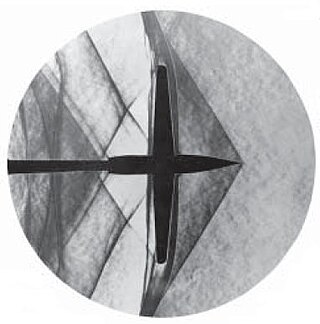
Schlieren photography is a process for photographing fluid flow. Invented by the German physicist August Toepler in 1864 to study supersonic motion, it is widely used in aeronautical engineering to photograph the flow of air around objects.

<span class="mw-page-title-main">Collimated beam</span> Light all pointing in the same direction

A collimated beam of light or other electromagnetic radiation has parallel rays, and therefore will spread minimally as it propagates. A perfectly collimated light beam, with no divergence, would not disperse with distance. However, diffraction prevents the creation of any such beam.

<span class="mw-page-title-main">Advanced Combat Optical Gunsight</span> American series of telescopic sights manufactured by Trijicon

The Advanced Combat Optical Gunsight (ACOG) is a series of prismatic telescopic sights manufactured by Trijicon. The ACOG was originally designed to be used on the M16 rifle and M4 carbine, but Trijicon has also developed ACOG accessories for other firearms. Models provide fixed-power magnification levels from 1.25× to 6×. ACOG reticles are illuminated at night by an internal tritium phosphor. Some versions have an additional daytime reticle illumination via a passive external fiberoptic light pipe or are LED-illuminated using a dry battery. The first ACOG model, known as the TA01, was released in 1987.

<span class="mw-page-title-main">Reticle</span> Aim markings in optical devices, e.g. crosshairs

A reticle, or reticule also known as a graticule, is a pattern of fine lines or markings built into the eyepiece of an optical device such as a telescopic sight, spotting scope, theodolite, optical microscope or the screen of an oscilloscope, to provide measurement references during visual inspections. Today, engraved lines or embedded fibers may be replaced by a digital image superimposed on a screen or eyepiece. Both terms may be used to describe any set of patterns used for aiding visual measurements and calibrations, but in modern use reticle is most commonly used for weapon sights, while graticule is more widely used for non-weapon measuring instruments such as oscilloscope display, astronomic telescopes, microscopes and slides, surveying instruments and other similar devices.

<span class="mw-page-title-main">Telescopic sight</span> Sighting device for firearms

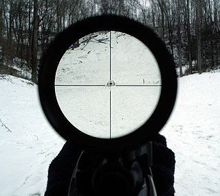
A telescopic sight, commonly called a scope informally, is an optical sighting device based on a refracting telescope. It is equipped with some form of a referencing pattern – known as a reticle – mounted in a focally appropriate position in its optical system to provide an accurate point of aim. Telescopic sights are used with all types of systems that require magnification in addition to reliable visual aiming, as opposed to non-magnifying iron sights, reflector (reflex) sights, holographic sights or laser sights, and are most commonly found on long-barrel firearms, particularly rifles, usually via a scope mount. Similar devices are also found on other platforms such as Artillery, Tanks and even Aircraft. The optical components may be combined with optoelectronics to add night vision or smart device features.

A collimator is a device which narrows a beam of particles or waves. To narrow can mean either to cause the directions of motion to become more aligned in a specific direction, or to cause the spatial cross section of the beam to become smaller.

<span class="mw-page-title-main">SUSAT</span>

The Sight Unit Small Arms, Trilux, or SUSAT, is a 4× telescopic sight, with tritium-powered illumination utilised at dusk or dawn. The full name of the current model is the SUSAT L9A1. The sight is not designed as a sniper sight, but is rather intended to be mounted on a variety of rifles and to be used by all infantrymen. A similar device is the Advanced Combat Optical Gunsight (ACOG).

<span class="mw-page-title-main">Sight (device)</span> Visual aiming device

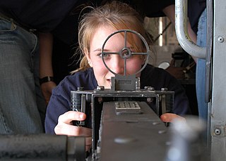
A sight or sighting device is any device used to assist in precise visual alignment of ranged weapons, surveying instruments, aircraft equipment or optical illumination equipments with the intended target. Sights can be a simple set or system of physical markers that serve as visual references for directly aligning the user's line of sight with the target, or optical instruments that provide an optically enhanced — often magnified — target image aligned in the same focus with an aiming point. There are also sights that actively project an illuminated point of aim onto the target itself so it can be observed by anyone with a direct view, such as laser sights and infrared illuminators on some night vision devices, as well as augmented or even virtual reality-enabled digital cameras with software algorithms that produce digitally enhanced target images.

<span class="mw-page-title-main">Boresight (firearm)</span>

Boresighting is a method of visually pre-aligning a firearm barrel's bore axis with the target, in order to more easily zero the gunsight. The process is usually performed on a rifle, and can be accomplished either with the naked eye, or with a specialized device called a boresighter.

Aimpoint AB is a Swedish optics company based in Malmö, Sweden that manufactures red dot sights.

<span class="mw-page-title-main">Finderscope</span>

A finderscope is an accessory sighting device used in astronomy and stargazing, typically a small auxiliary refracting telescope/monocular mounted parallelly on a larger astronomical telescope along the same line of sight. The finderscope usually has a much smaller magnification than the main telescope, thus providing a larger field of view, useful for manually pointing the main telescope into a roughly correct direction that can easily place a desired astronomical object in view when zooming in. Some finderscopes have sophisticated reticles to more accurately aim the main telescope and/or even perform stadiometric measurements.

<span class="mw-page-title-main">Howard Grubb</span>

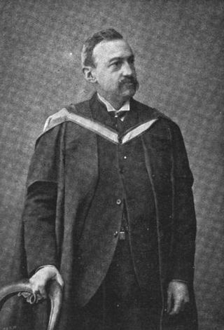
Sir Howard Grubb was an optical designer from Dublin, Ireland. He was head of a family firm that made large optical telescopes, telescope drive controls, and other optical instruments. He is also noted for his work to perfect the periscope and inventing the reflector sight.

<span class="mw-page-title-main">Red dot sight</span> Type of firearm reflector sight

A red dot sight is a common classification for a non-magnifying reflector sight that provides an illuminated red dot to the user as a point of aim. A standard design uses a red light-emitting diode (LED) at the focus of collimating optics, which generates a dot-style illuminated reticle that stays in alignment with the weapon the sight is attached to, regardless of eye position.

<span class="mw-page-title-main">Holographic weapon sight</span> Type of gunsight

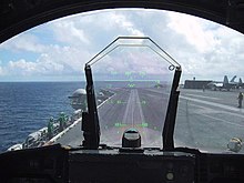
A holographic weapon sight or holographic diffraction sight is a non-magnifying gunsight that allows the user to look through a glass optical window and see a holographic reticle image superimposed at a distance on the field of view. The hologram of the reticle is built into the window and is illuminated by a laser diode.

<span class="mw-page-title-main">Collimator sight</span>

A collimator sight is a type of optical sight that allows the user looking into it to see an illuminated aiming point aligned with the device the sight is attached to, regardless of eye position. They are also referred to as collimating sights or "occluded eye gunsight" (OEG).

<span class="mw-page-title-main">Sight magnifier</span> Type of firearm sight accessory

A sight magnifier is an optical telescope that can be paired with a non-magnifying optical sight on a weapon to create a telescopic sight. They work with the parallel collimated reticle image produced by red dot sights and holographic weapon sights. They may synonymously be referred to as a red dot magnifier, reflex sight magnifier, holographic sight magnifier, or flip to side magnifiers.

<span class="mw-page-title-main">Prism sight</span>

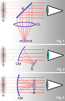
A prism sight or prismatic sight, sometimes also called prism scope or prismatic scope, is a type telescopic sight which uses a reflective prism for its image-erecting system, instead of the series of relay lenses found in traditional telescopic sights. The use of prisms makes it possible to construct a shorter and lighter sight, or with an offset between the eyepiece and objective axes.

References

  1. "Elementary Optics and Application to Fire Control Instruments". Headquarters, Department of the Army. 13 April 1977. Retrieved 13 April 2018 via Google Books.
  2. 1 2 Company, McGraw-Hill Book (13 April 2018). McGraw-Hill encyclopedia of science and technology. McGraw-Hill. ISBN   9780079136657 . Retrieved 13 April 2018 via Google Books.
  3. 1 2 3 "Encyclopedia of Bullseye Pistol". www.bullseyepistol.com. Retrieved 13 April 2018.
  4. 1 2 3 American rifleman: Volume 93, National Rifle Association of America - THE REFLECTOR SIGHT By JOHN B. BUTLER, page 31
  5. Ray, Sidney F. (13 April 2018). Applied Photographic Optics: Lenses and Optical Systems for Photography, Film, Video, Electronic and Digital Imaging. Focal. ISBN   9780240515403 . Retrieved 13 April 2018 via Google Books.
  6. "BAZOOKA M9A1". usmilitariaforum.com. Retrieved 13 April 2018.
  7. American rifleman: Volume 93, National Rifle Association of America - THE REFLECTOR SIGHT By JOHN B. BUTLER, page 29
  8. "Science Progress". John Murray. 13 April 1992. Retrieved 13 April 2018 via Google Books.
  9. Lockyer, Sir Norman (1902). Nature. Macmillan Journals Limited. p.  227 . Retrieved 13 April 2018 via Internet Archive. grubb for sighting devices for guns.
  10. 1 2 "The Scientific Transactions of the Royal Dublin Society". The Society. 13 April 2018. Retrieved 13 April 2018 via Google Books.
  11. "The Mining engineer, Volume 23 By Institution of Mining Engineers (Great Britain). THE GRUBB SIGHT FOR SURVEYING INSTRUMENTS By Sir HOWARD GRUBB and HENRY DAVIS". google.com. 1903. Retrieved 13 April 2018.
  12. Harry Woodman (1989). Early aircraft armament: the aeroplane and the gun up to 1918. p. 239. ISBN   9780874749946.
  13. 1 2 British Aircraft Armament Vol.2: Guns and Gunsights", by R Wallace Clarke, page 134
  14. Ohio, United States Document Service Center, Dayton (13 April 2018). "Technical Data Digest" . Retrieved 13 April 2018 via Google Books.{{cite web}}: CS1 maint: multiple names: authors list (link)
  15. Applied physics Chauncey Guy Suits, George Russell Harrison, Louis Jordan - 1948, page 222 - "One of the most important types of gun sights used by the Army and Navy during the war was the reflex, or reflector, sight."
  16. Applied optics and optical engineering, Volume 5, Part 2 - Page 198 Rudolf Kingslake, Robert Rennie Shannon, James C. Wyant Applied optics and optical engineering, Volume 5, Part 2 - Page 198
  17. Shideler, Dan (14 July 2010). Gun Digest 2011. Krause Publications. ISBN   9781440215612 . Retrieved 13 April 2018 via Google Books.
  18. Transactions, Volume 23 By Institution of Mining Engineers (Great Britain), Federated Institution of Mining Engineers, page 125
  19. Jones, Tony L. (1 January 2002). The Police Officer's Guide to Operating and Surviving in Low-light and No-light Conditions: How to Prevail in Stressful Situations Through Proper Decision Making and Instruction on the Use and Availability of Illumination Tools. Charles C Thomas Publisher. ISBN   9780398072537 . Retrieved 13 April 2018 via Google Books.
  20. "Aircraft Gunnery_Sights". liberatorcrew.com. Retrieved 13 April 2018.
  21. 1 2 Lon O. Nordeen, Air warfare in the missile age, page 265
  22. Jarrett, D. N. (13 April 2018). Cockpit Engineering. Ashgate Pub. ISBN   9780754617518 . Retrieved 13 April 2018 via Google Books.
  23. Game breeder and sportsman: Volumes 50-52, 1945
  24. U.S. Patent 2633051A
  25. "Stock Up For the Outdoors", Popular Science - Dec 1946- Vol. 149, No. 6 - page 150
  26. Popular Science - Sep 1971 - Page 56
  27. Invention intelligence: Volume 11, Inventions Promotion Board, National Research Development Corporation of India, 1976, page 12
  28. "Hearings before and special reports made by Committee on Armed Services of the House of Representatives on subjects affecting the naval and military establishments", Volume 980 - Page 3002 United States. Congress. House. Committee on Armed Services - Political Science, 1975
  29. McIntyre, Thomas (1 December 2007). The Field and Stream Hunting Optics Handbook: An Expert's Guide to Riflescopes, Binoculars, Spotting Scopes, and Rangefinders. Lyons Press. ISBN   9781599210445 . Retrieved 13 April 2018 via Google Books.
  30. "The Hines Lensless Optical Viewfinder". hineslab.com. Archived from the original on 23 March 2012. Retrieved 13 April 2018.
  31. "Telrad Sight". Company Seven. Retrieved 17 January 2016.
  32. Mullaney, James (26 May 2007). A Buyer's and User's Guide to Astronomical Telescopes & Binoculars. Springer Science & Business Media. ISBN   9781846287077 . Retrieved 13 April 2018 via Google Books.
  33. Lighting dimensions, Volume 19, Page 114, Lighting Dimensions Associates, 1995
  34. William C Farmer, Ordnance field guide, page 279
  35. Jan Kay, International Defense Directory, 1991-92, page 241
  36. Dept, United States Army Ordnance (13 April 2018). "Elementary Optics and Applications to Fire Control Instruments: May, 1921". U.S. Government Printing Office. Retrieved 13 April 2018 via Google Books.
  37. Magazines, Hearst (1 September 1970). "Popular Mechanics". Hearst Magazines. Retrieved 13 April 2018 via Google Books.
  38. ""Compact Holographic Sight" - EOTech company Patent #5,483,362 issued January 9, 1996" (PDF). google.com. Retrieved 13 April 2018.

Further reading