Ringing artifacts

Last updated
Image showing ringing artifacts. 3 levels on each side of transition: overshoot, first ring, and (faint) second ring. Ringing artifact example.png
Image showing ringing artifacts. 3 levels on each side of transition: overshoot, first ring, and (faint) second ring.
Same image without ringing artifacts. Ringing artifact example - original.png
Same image without ringing artifacts.

In signal processing, particularly digital image processing, ringing artifacts are artifacts that appear as spurious signals near sharp transitions in a signal. Visually, they appear as bands or "ghosts" near edges; audibly, they appear as "echos" near transients, particularly sounds from percussion instruments; most noticeable are the pre-echos. The term "ringing" is because the output signal oscillates at a fading rate around a sharp transition in the input, similar to a bell after being struck. As with other artifacts, their minimization is a criterion in filter design.

Contents

Introduction

The main cause of ringing artifacts is overshoot and oscillations in the step response of a filter. High accuracy settling time measurements figure 1.png
The main cause of ringing artifacts is overshoot and oscillations in the step response of a filter.

The main cause of ringing artifacts is due to a signal being bandlimited (specifically, not having high frequencies) or passed through a low-pass filter; this is the frequency domain description. In terms of the time domain, the cause of this type of ringing is the ripples in the sinc function, [1] which is the impulse response (time domain representation) of a perfect low-pass filter. Mathematically, this is called the Gibbs phenomenon.

One may distinguish overshoot (and undershoot), which occurs when transitions are accentuated – the output is higher than the input – from ringing, where after an overshoot, the signal overcorrects and is now below the target value; these phenomena often occur together, and are thus often conflated and jointly referred to as "ringing".

The term "ringing" is most often used for ripples in the time domain, though it is also sometimes used for frequency domain effects: [2] windowing a filter in the time domain by a rectangular function causes ripples in the frequency domain for the same reason as a brick-wall low pass filter (rectangular function in the frequency domain) causes ripples in the time domain, in each case the Fourier transform of the rectangular function being the sinc function.

There are related artifacts caused by other frequency domain effects, and similar artifacts due to unrelated causes.

Causes

Description

The sinc function, the impulse response for an ideal low-pass filter, illustrating ringing for an impulse. Sinc function (normalized).svg
The sinc function, the impulse response for an ideal low-pass filter, illustrating ringing for an impulse.
The Gibbs phenomenon, illustrating ringing for a step function. Gibbs phenomenon 10.svg
The Gibbs phenomenon, illustrating ringing for a step function.

By definition, ringing occurs when a non-oscillating input yields an oscillating output: formally, when an input signal which is monotonic on an interval has output response which is not monotonic. This occurs most severely when the impulse response or step response of a filter has oscillations – less formally, if for a spike input, respectively a step input (a sharp transition), the output has bumps. Ringing most commonly refers to step ringing, and that will be the focus.

Ringing is closely related to overshoot and undershoot, which is when the output takes on values higher than the maximum (respectively, lower than the minimum) input value: one can have one without the other, but in important cases, such as a low-pass filter, one first has overshoot, then the response bounces back below the steady-state level, causing the first ring, and then oscillates back and forth above and below the steady-state level. Thus overshoot is the first step of the phenomenon, while ringing is the second and subsequent steps. Due to this close connection, the terms are often conflated, with "ringing" referring to both the initial overshoot and the subsequent rings.

If one has a linear time invariant (LTI) filter, then one can understand the filter and ringing in terms of the impulse response (the time domain view), or in terms of its Fourier transform, the frequency response (the frequency domain view). Ringing is a time domain artifact, and in filter design is traded off with desired frequency domain characteristics: the desired frequency response may cause ringing, while reducing or eliminating ringing may worsen the frequency response.

sinc filter

The Sine integral for positive values, exhibiting oscillation. Sine integral.svg
The Sine integral for positive values, exhibiting oscillation.

The central example, and often what is meant by "ringing artifacts", is the ideal (brick-wall) low-pass filter, the sinc filter. This has an oscillatory impulse response function, as illustrated above, and the step response – its integral, the sine integral – thus also features oscillations, as illustrated at right.

These ringing artifacts are not results of imperfect implementation or windowing: the ideal low-pass filter, while possessing the desired frequency response, necessarily causes ringing artifacts in the time domain.

Time domain

In terms of impulse response, the correspondence between these artifacts and the behavior of the function is as follows:

Turning to step response, the step response is the integral of the impulse response; formally, the value of the step response at time a is the integral of the impulse response. Thus values of the step response can be understood in terms of tail integrals of the impulse response.

Assume that the overall integral of the impulse response is 1, so it sends constant input to the same constant as output – otherwise the filter has gain, and scaling by gain gives an integral of 1.

The impulse response may have many negative lobes, and thus many oscillations, each yielding a ring, though these decay for practical filters, and thus one generally only sees a few rings, with the first generally being most pronounced.

Note that if the impulse response has small negative lobes and larger positive lobes, then it will exhibit ringing but not undershoot or overshoot: the tail integral will always be between 0 and 1, but will oscillate down at each negative lobe. However, in the sinc filter, the lobes monotonically decrease in magnitude and alternate in sign, as in the alternating harmonic series, and thus tail integrals alternate in sign as well, so it exhibits overshoot as well as ringing.

Conversely, if the impulse response is always nonnegative, so it has no negative lobes – the function is a probability distribution – then the step response will exhibit neither ringing nor overshoot or undershoot – it will be a monotonic function growing from 0 to 1, like a cumulative distribution function. Thus the basic solution from the time domain perspective is to use filters with nonnegative impulse response.

Frequency domain

The frequency domain perspective is that ringing is caused by the sharp cut-off in the rectangular passband in the frequency domain, and thus is reduced by smoother roll-off, as discussed below. [1] [4]

Solutions

Solutions depend on the parameters of the problem: if the cause is a low-pass filter, one may choose a different filter design, which reduces artifacts at the expense of worse frequency domain performance. On the other hand, if the cause is a band-limited signal, as in JPEG, one cannot simply replace a filter, and ringing artifacts may prove hard to fix – they are present in JPEG 2000 and many audio compression codecs (in the form of pre-echo), as discussed in the examples.

Low-pass filter

The Gaussian function is non-negative and non-oscillating, hence causes no overshoot or ringing. DisNormal01.svg
The Gaussian function is non-negative and non-oscillating, hence causes no overshoot or ringing.

If the cause is the use of a brick-wall low-pass filter, one may replace the filter with one that reduces the time domain artifacts, at the cost of frequency domain performance. This can be analyzed from the time domain or frequency domain perspective.

In the time domain, the cause is an impulse response that oscillates, assuming negative values. This can be resolved by using a filter whose impulse response is non-negative and does not oscillate, but shares desired traits. For example, for a low-pass filter, the Gaussian filter is non-negative and non-oscillatory, hence causes no ringing. However, it is not as good as a low-pass filter: it rolls off in the passband, and leaks in the stopband: in image terms, a Gaussian filter "blurs" the signal, which reflects the attenuation of desired higher frequency signals in the passband.

A general solution is to use a window function on the sinc filter, which cuts off or reduces the negative lobes: these respectively eliminate and reduce overshoot and ringing. Note that truncating some but not all of the lobes eliminates the ringing beyond that point, but does not reduce the amplitude of the ringing that is not truncated (because this is determined by the size of the lobe), and increases the magnitude of the overshoot if the last non-cut lobe is negative, since the magnitude of the overshoot is the integral of the tail, which is no longer canceled by positive lobes.

Further, in practical implementations one at least truncates sinc, otherwise one must use infinitely many data points (or rather, all points of the signal) to compute every point of the output – truncation corresponds to a rectangular window, and makes the filter practically implementable, but the frequency response is no longer perfect. [5] In fact, if one takes a brick wall low-pass filter (sinc in time domain, rectangular in frequency domain) and truncates it (multiplies with a rectangular function in the time domain), this convolves the frequency domain with sinc (Fourier transform of the rectangular function) and causes ringing in the frequency domain, [2] which is referred to as ripple. In symbols, The frequency ringing in the stopband is also referred to as side lobes. Flat response in the passband is desirable, so one windows with functions whose Fourier transform has fewer oscillations, so the frequency domain behavior is better.

Multiplication in the time domain corresponds to convolution in the frequency domain, so multiplying a filter by a window function corresponds to convolving the Fourier transform of the original filter by the Fourier transform of the window, which has a smoothing effect – thus windowing in the time domain corresponds to smoothing in the frequency domain, and reduces or eliminates overshoot and ringing. [6]

In the frequency domain, the cause can be interpreted as due to the sharp (brick-wall) cut-off, and ringing reduced by using a filter with smoother roll-off. [1] This is the case for the Gaussian filter, whose magnitude Bode plot is a downward opening parabola (quadratic roll-off), as its Fourier transform is again a Gaussian, hence (up to scale) – taking logarithms yields

External image
Searchtool.svg Butterworth filter impulse response and frequency response graphs [7]

In electronic filters, the trade-off between frequency domain response and time domain ringing artifacts is well-illustrated by the Butterworth filter: the frequency response of a Butterworth filter slopes down linearly on the log scale, with a first-order filter having slope of −6 dB per octave, a second-order filter –12 dB per octave, and an nth order filter having slope of dB per octave – in the limit, this approaches a brick-wall filter. Thus, among these the, first-order filter rolls off slowest, and hence exhibits the fewest time domain artifacts, but leaks the most in the stopband, while as order increases, the leakage decreases, but artifacts increase. [4]

Benefits

While ringing artifacts are generally considered undesirable, the initial overshoot (haloing) at transitions increases acutance (apparent sharpness) by increasing the derivative across the transition, and thus can be considered as an enhancement. [8]

Overshoot

The sinc function has negative tail integrals, hence has overshoot. Sinc function (normalized).svg
The sinc function has negative tail integrals, hence has overshoot.

Another artifact is overshoot (and undershoot), which manifests itself not as rings, but as an increased jump at the transition. It is related to ringing, and often occurs in combination with it.

Overshoot and undershoot are caused by a negative tail – in the sinc, the integral from the first zero to infinity, including the first negative lobe. While ringing is caused by a following positive tail – in sinc, the integral from the second zero to infinity, including the first non-central positive lobe. Thus overshoot is necessary for ringing,[ dubious ] but can occur separately: for example, the 2-lobed Lanczos filter has only a single negative lobe on each side, with no following positive lobe, and thus exhibits overshoot but no ringing, while the 3-lobed Lanczos filter exhibits both overshoot and ringing, though the windowing reduces this compared to the sinc filter or the truncated sinc filter.

Similarly, the convolution kernel used in bicubic interpolation is similar to a 2-lobe windowed sinc, taking on negative values, and thus produces overshoot artifacts, which appear as halos at transitions.

Clipping

Following from overshoot and undershoot is clipping. If the signal is bounded, for instance an 8-bit or 16-bit integer, this overshoot and undershoot can exceed the range of permissible values, thus causing clipping.

Strictly speaking, the clipping is caused by the combination of overshoot and limited numerical accuracy, but it is closely associated with ringing, and often occurs in combination with it.

Clipping can also occur for unrelated reasons, from a signal simply exceeding the range of a channel.

On the other hand, clipping can be exploited to conceal ringing in images. Some modern JPEG codecs, such as mozjpeg and ISO libjpeg, use such a trick to reduce ringing by deliberately causing overshoots in the IDCT results. [9] This idea originated in a mozjpeg patch. [10]

Ringing and ripple

Frequency response of a 5th order Chebyshev filter, exhibiting ripple. Chebyscheff5.svg
Frequency response of a 5th order Chebyshev filter, exhibiting ripple.

In signal processing and related fields, the general phenomenon of time domain oscillation is called ringing, while frequency domain oscillations are generally called ripple, though generally not "rippling".

A key source of ripple in digital signal processing is the use of window functions: if one takes an infinite impulse response (IIR) filter, such as the sinc filter, and windows it to make it have finite impulse response, as in the window design method, then the frequency response of the resulting filter is the convolution of the frequency response of the IIR filter with the frequency response of the window function. Notably, the frequency response of the rectangular filter is the sinc function (the rectangular function and the sinc function are Fourier dual to each other), and thus truncation of a filter in the time domain corresponds to multiplication by the rectangular filter, thus convolution by the sinc filter in the frequency domain, causing ripple. In symbols, the frequency response of is In particular, truncating the sinc function itself yields in the time domain, and in the frequency domain, so just as low-pass filtering (truncating in the frequency domain) causes ringing in the time domain, truncating in the time domain (windowing by a rectangular filter) causes ripple in the frequency domain.

Examples

JPEG

Extreme example of JPEG artifacts, including ringing: cyan (= white minus red) rings around a red star. Asterisk with jpg-artefacts.png
Extreme example of JPEG artifacts, including ringing: cyan (= white minus red) rings around a red star.

JPEG compression can introduce ringing artifacts at sharp transitions, which are particularly visible in text.

This is a due to loss of high frequency components, as in step response ringing. JPEG uses 8×8 blocks, on which the discrete cosine transform (DCT) is performed. The DCT is a Fourier-related transform, and ringing occurs because of loss of high frequency components or loss of precision in high frequency components.

They can also occur at the edge of an image: since JPEG splits images into 8×8 blocks, if an image is not an integer number of blocks, the edge cannot easily be encoded, and solutions such as filling with a black border create a sharp transition in the source, hence ringing artifacts in the encoded image.

Ringing also occurs in the wavelet-based JPEG 2000.

JPEG and JPEG 2000 have other artifacts, as illustrated above, such as blocking ("jaggies") and edge busyness ("mosquito noise"), though these are due to specifics of the formats, and are not ringing as discussed here.

Some illustrations:

ImageLossless compressionLossy compression
Original Lossless-circle.png Lossy-circle.jpg
Processed by
Canny edge detector,
highlighting artifacts.
Lossless-circle-canny.png Lossy-circle-canny.png

Pre-echo

In audio signal processing, ringing can cause echoes to occur before and after transients, such as the impulsive sound from percussion instruments, such as cymbals (this is impulse ringing). The (causal) echo after the transient is not heard, because it is masked by the transient, an effect called temporal masking. Thus only the (anti-causal) echo before the transient is heard, and the phenomenon is called pre-echo.

This phenomenon occurs as a compression artifact in audio compression algorithms that use Fourier-related transforms, such as MP3, AAC, and Vorbis.

Similar phenomena

Other phenomena have similar symptoms to ringing, but are otherwise distinct in their causes. In cases where these cause circular artifacts around point sources, these may be referred to as "rings" due to the round shape (formally, an annulus), which is unrelated to the "ringing" (oscillatory decay) frequency phenomenon discussed on this page.

Edge enhancement

Edge enhancement, which aims to increase edges, may cause ringing phenomena, particularly under repeated application, such as by a DVD player followed by a television. This may be done by high-pass filtering, rather than low-pass filtering. [4]

Special functions

The Airy pattern, caused by Fraunhofer diffraction. Airy-pattern.svg
The Airy pattern, caused by Fraunhofer diffraction.

Many special functions exhibit oscillatory decay, and thus convolving with such a function yields ringing in the output; one may consider these ringing, or restrict the term to unintended artifacts in frequency domain signal processing.

Fraunhofer diffraction yields the Airy disk as point spread function, which has a ringing pattern.

The Bessel function of the first kind, which is related to the Airy function, exhibits such decay.

In cameras, a combination of defocus and spherical aberration can yield circular artifacts ("ring" patterns). However, the pattern of these artifacts need not be similar to ringing (as discussed on this page) – they may exhibit oscillatory decay (circles of decreasing intensity), or other intensity patterns, such as a single bright band.

Interference

Ghosting is a form of television interference where an image is repeated. Though this is not ringing, it can be interpreted as convolution with a function, which is 1 at the origin and ε (the intensity of the ghost) at some distance, which is formally similar to the above functions (a single discrete peak, rather than continuous oscillation).

Lens flare

In photography, lens flare is a defect where various circles can appear around highlights, and with ghosts throughout a photo, due to undesired light, such as reflection and scattering off elements in the lens.

Visual illusions

Visual illusions can occur at transitions, as in Mach bands, which perceptually exhibit a similar undershoot/overshoot to the Gibbs phenomenon.

See also

Related Research Articles

Nyquist–Shannon sampling theorem Sufficiency theorem for reconstructing signals from samples

The Nyquist–Shannon sampling theorem is a theorem in the field of signal processing which serves as a fundamental bridge between continuous-time signals and discrete-time signals. It establishes a sufficient condition for a sample rate that permits a discrete sequence of samples to capture all the information from a continuous-time signal of finite bandwidth.

Wavelet Function for integral Fourier-like transform

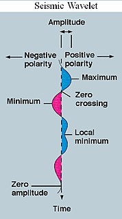
A wavelet is a wave-like oscillation with an amplitude that begins at zero, increases or decreases, and then returns to zero one or more times. Wavelets are termed a "brief oscillation". A taxonomy of wavelets has been established, based on the number and direction of its pulses. Wavelets are imbued with specific properties that make them useful for signal processing.

A low-pass filter is a filter that passes signals with a frequency lower than a selected cutoff frequency and attenuates signals with frequencies higher than the cutoff frequency. The exact frequency response of the filter depends on the filter design. The filter is sometimes called a high-cut filter, or treble-cut filter in audio applications. A low-pass filter is the complement of a high-pass filter.

Window function Function used in signal processing

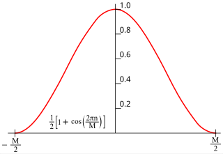
In signal processing and statistics, a window function is a mathematical function that is zero-valued outside of some chosen interval, normally symmetric around the middle of the interval, usually near a maximum in the middle, and usually tapering away from the middle. Mathematically, when another function or waveform/data-sequence is "multiplied" by a window function, the product is also zero-valued outside the interval: all that is left is the part where they overlap, the "view through the window". Equivalently, and in actual practice, the segment of data within the window is first isolated, and then only that data is multiplied by the window function values. Thus, tapering, not segmentation, is the main purpose of window functions.

Sinc filter

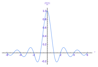
In signal processing, a sinc filter is an idealized filter that removes all frequency components above a given cutoff frequency, without affecting lower frequencies, and has linear phase response. The filter's impulse response is a sinc function in the time domain, and its frequency response is a rectangular function.

Undersampling

In signal processing, undersampling or bandpass sampling is a technique where one samples a bandpass-filtered signal at a sample rate below its Nyquist rate, but is still able to reconstruct the signal.

In mathematics, the Gibbs phenomenon, discovered by Henry Wilbraham (1848) and rediscovered by J. Willard Gibbs (1899), is the oscillatory behavior of the Fourier series of a piecewise continuously differentiable periodic function around a jump discontinuity. The function's th partial Fourier series produces large peaks around the jump which overshoot and undershoot the function's actual values. This approximation error approaches a limit of about 9% of the jump as more sinusoids are used, though the infinite Fourier series sum does eventually converge almost everywhere except the point of discontinuity.

Analog signal processing is a type of signal processing conducted on continuous analog signals by some analog means. "Analog" indicates something that is mathematically represented as a set of continuous values. This differs from "digital" which uses a series of discrete quantities to represent signal. Analog values are typically represented as a voltage, electric current, or electric charge around components in the electronic devices. An error or noise affecting such physical quantities will result in a corresponding error in the signals represented by such physical quantities.

In signal processing, a finite impulse response (FIR) filter is a filter whose impulse response is of finite duration, because it settles to zero in finite time. This is in contrast to infinite impulse response (IIR) filters, which may have internal feedback and may continue to respond indefinitely.

Pulse (signal processing) Quick, temporary change in amplitude of elecrtical signals

A pulse in signal processing is a rapid, transient change in the amplitude of a signal from a baseline value to a higher or lower value, followed by a rapid return to the baseline value.

Linear time-invariant system Mathematical model

In system analysis, among other fields of study, a linear time-invariant system is a system that produces an output signal from any input signal subject to the constraints of linearity and time-invariance; these terms are briefly defined below. These properties apply to many important physical systems, in which case the response y(t) of the system to an arbitrary input x(t) can be found directly using convolution: y(t) = x(t) ∗ h(t) where h(t) is called the system's impulse response and ∗ represents convolution. What's more, there are systematic methods for solving any such system, whereas systems not meeting both properties are generally more difficult to solve analytically. A good example of an LTI system is any electrical circuit consisting of resistors, capacitors, inductors and linear amplifiers.

In a mixed-signal system, a reconstruction filter, sometimes called an anti-imaging filter, is used to construct a smooth analog signal from a digital input, as in the case of a digital to analog converter (DAC) or other sampled data output device.

Lanczos resampling Application of a mathematical formula

Lanczos filtering and Lanczos resampling are two applications of a mathematical formula. It can be used as a low-pass filter or used to smoothly interpolate the value of a digital signal between its samples. In the latter case it maps each sample of the given signal to a translated and scaled copy of the Lanczos kernel, which is a sinc function windowed by the central lobe of a second, longer, sinc function. The sum of these translated and scaled kernels is then evaluated at the desired points.

The zero-order hold (ZOH) is a mathematical model of the practical signal reconstruction done by a conventional digital-to-analog converter (DAC). That is, it describes the effect of converting a discrete-time signal to a continuous-time signal by holding each sample value for one sample interval. It has several applications in electrical communication.

First-order hold (FOH) is a mathematical model of the practical reconstruction of sampled signals that could be done by a conventional digital-to-analog converter (DAC) and an analog circuit called an integrator. For FOH, the signal is reconstructed as a piecewise linear approximation to the original signal that was sampled. A mathematical model such as FOH is necessary because, in the sampling and reconstruction theorem, a sequence of Dirac impulses, xs(t), representing the discrete samples, x(nT), is low-pass filtered to recover the original signal that was sampled, x(t). However, outputting a sequence of Dirac impulses is impractical. Devices can be implemented, using a conventional DAC and some linear analog circuitry, to reconstruct the piecewise linear output for either predictive or delayed FOH.

Gaussian filter

In electronics and signal processing, a Gaussian filter is a filter whose impulse response is a Gaussian function. Gaussian filters have the properties of having no overshoot to a step function input while minimizing the rise and fall time. This behavior is closely connected to the fact that the Gaussian filter has the minimum possible group delay. It is considered the ideal time domain filter, just as the sinc is the ideal frequency domain filter. These properties are important in areas such as oscilloscopes and digital telecommunication systems.

In electronics and telecommunications, pulse shaping is the process of changing the waveform of transmitted pulses. Its purpose is to make the transmitted signal better suited to its purpose or the communication channel, typically by limiting the effective bandwidth of the transmission. By filtering the transmitted pulses this way, the intersymbol interference caused by the channel can be kept in control. In RF communication, pulse shaping is essential for making the signal fit in its frequency band.

Overshoot (signal)

In signal processing, control theory, electronics, and mathematics, overshoot is the occurrence of a signal or function exceeding its target. Undershoot is the same phenomenon in the opposite direction. It arises especially in the step response of bandlimited systems such as low-pass filters. It is often followed by ringing, and at times conflated with the latter.

Ringing (signal)

In electronics, signal processing, and video, ringing is oscillation of a signal, particularly in the step response. Often ringing is undesirable, but not always, as in the case of resonant inductive coupling. It is also known as hunting. It is closely related to overshoot, often instigated as damping response following overshoot or undershoot, and thus the terms are at times conflated.

The chirp pulse compression process transforms a long duration frequency-coded pulse into a narrow pulse of greatly increased amplitude. It is a technique used in radar and sonar systems because it is a method whereby a narrow pulse with high peak power can be derived from a long duration pulse with low peak power. Furthermore, the process offers good range resolution because the half-power beam width of the compressed pulse is consistent with the system bandwidth.

References

  1. 1 2 3 Bankman, Isaac N. (2000), Handbook of medical imaging, Academic Press, ISBN   978-0-12-077790-7 , section I.6, Enhancement: Frequency Domain Techniques, p. 16
  2. 1 2 Digital Signal Processing, by J.S.Chitode, Technical Publications, 2008, ISBN   978-81-8431-346-8, 4 - 70
  3. Glassner, Andrew S (2004), Principles of Digital Image Synthesis (2 ed.), Morgan Kaufmann, ISBN   978-1-55860-276-2 , p. 518
  4. 1 2 3 Microscope Image Processing, by Qiang Wu, Fatima Merchant, Kenneth Castleman, ISBN   978-0-12-372578-3 p. 71
  5. ( Allen & Mills 2004 ) Section 9.3.1.1 Ideal Filters: Low pass, p. 621
  6. ( Allen & Mills 2004 ) p. 623
  7. Op Amp applications handbook, by Walter G. Jung, Newnes, 2004, ISBN   978-0-7506-7844-5, p. 332
  8. Mitchell, Don P.; Netravali, Arun N. (August 1988). Reconstruction filters in computer-graphics (PDF). ACM SIGGRAPH International Conference on Computer Graphics and Interactive Techniques. Vol. 22. pp. 221–228. doi:10.1145/54852.378514. ISBN   0-89791-275-6.
  9. Richter, Thomas (September 2016). "JPEG on STEROIDS: Common optimization techniques for JPEG image compression". 2016 IEEE International Conference on Image Processing (ICIP): 61–65. doi:10.1109/ICIP.2016.7532319.
  10. Lesiński, Kornel. "Deringing in DCT via overshoot and clipping". kornel.ski.