X-ray optics

Last updated

X-ray optics is the branch of optics that manipulates X-rays instead of visible light. It deals with focusing and other ways of manipulating the X-ray beams for research techniques such as X-ray diffraction, X-ray crystallography, X-ray fluorescence, small-angle X-ray scattering, X-ray microscopy, X-ray phase-contrast imaging, and X-ray astronomy.

Contents

Since X-rays and visible light are both electromagnetic waves they propagate in space in the same way, but because of the much higher frequency and photon energy of X-rays they interact with matter very differently. Visible light is easily redirected using lenses and mirrors, but because the real part of the complex refractive index of all materials is very close to 1 for X-rays, [1] they instead tend to initially penetrate and eventually get absorbed in most materials without changing direction much.

X-ray techniques

There are many different techniques used to redirect X-rays, most of them changing the directions by only minute angles. The most common principle used is reflection at grazing incidence angles, either using total external reflection at very small angles or multilayer coatings. Other principles used include diffraction and interference in the form of zone plates, refraction in compound refractive lenses that use many small X-ray lenses in series to compensate by their number for the minute index of refraction, Bragg reflection from a crystal plane in flat or bent crystals.

X-ray beams are often collimated or reduced in size using pinholes or movable slits typically made of tungsten or some other high-Z material. Narrow parts of an X-ray spectrum can be selected with monochromators based on one or multiple Bragg reflections by crystals. X-ray spectra can also be manipulated by having the X-rays pass through a filter (optics). This will typically reduce the low-energy part of the spectrum, and possibly parts above absorption edges of the elements used for the filter.

Focusing optics

Analytical X-ray techniques such as X-ray crystallography, small-angle X-ray scattering, wide-angle X-ray scattering, X-ray fluorescence, X-ray spectroscopy and X-ray photoelectron spectroscopy all benefit from high X-ray flux densities on the samples being investigated. This is achieved by focusing the divergent beam from the X-ray source onto the sample using one out of a range of focusing optical components. This is also useful for scanning probe techniques such as scanning transmission X-ray microscopy and scanning X-ray fluorescence imaging.

Polycapillary optics

A polycapillary lens for focusing X-rays Polycapillary lens.jpg
A polycapillary lens for focusing X-rays

Polycapillary lenses are arrays of small hollow glass tubes that guide the X-rays with many total external reflections on the inside of the tubes. [2] The array is tapered so that one end of the capillaries points at the X-ray source and the other at the sample. Polycapillary optics are achromatic and thus suitable for scanning fluorescence imaging and other applications where a broad X-ray spectrum is useful. They collect X-rays efficiently for photon energies of 0.1 to 30  keV and can achieve gains of 100 to 10000 in flux over using a pinhole at 100 mm from the X-ray source. [3] Since only X-rays entering the capillaries within a very narrow angle will be totally internally reflected, only X-rays coming from a small spot will be transmitted through the optic. Polycapillary optics cannot image more than one point to another, so they are used for illumination and collection of X-rays.

Zone plates

Zone plates consist of a substrate with concentric zones of a phase-shifting or absorbing material with zones getting narrower the larger their radius. The zone widths are designed so that a transmitted wave gets constructive interference in a single point giving a focus. [4] Zone plates can be used as condensers to collect light, but also for direct full-field imaging in e.g. an X-ray microscope. Zone plates are highly chromatic and usually designed only for a narrow energy span, making it necessary to have monochromatic X-rays for efficient collection and high-resolution imaging.

Compound refractive lenses

Since refractive indices at X-ray wavelengths are so close to 1, the focal lengths of normal lenses get impractically long. To overcome this, lenses with very small radii of curvature are used, and they are stacked in long rows, so that the combined focusing power gets appreciable. [5] Since the refractive index is less than 1 for X-rays, these lenses must be concave to achieve focusing, contrary to visible-light lenses, which are convex for a focusing effect. Radii of curvature are typically less than a millimeter, making the usable X-ray beam width at most about 1 mm. [6] To reduce the absorption of X-rays in these stacks, materials with very low atomic number such as beryllium or lithium are often used. Lenses from other materials are also on the market: radiation resistant polymer (Epoxy based) such as SU-8, nickel and silicon. Since the refractive index depends strongly on X-ray wavelength, these lenses are highly chromatic, and the variation of the focal length with wavelength must be taken into account for any application.

Reflection

Designs based on grazing-incidence reflection used in X-ray telescopes include that by Kirkpatrick-Baez, and several by Wolter (Wolter I-IV) Xray telescope lens.svg
Designs based on grazing-incidence reflection used in X-ray telescopes include that by Kirkpatrick–Baez, and several by Wolter (Wolter I–IV)

The basic idea is to reflect a beam of X-rays from a surface and to measure the intensity of X-rays reflected in the specular direction (reflected angle equal to incident angle). It has been shown that a reflection off a parabolic mirror followed by a reflection off a hyperbolic mirror leads to the focusing of X-rays. [7] Since the incoming X-rays must strike the tilted surface of the mirror, the collecting area is small. It can, however, be increased by nesting arrangements of mirrors inside each other. [8]

The ratio of reflected intensity to incident intensity is the X-ray reflectivity for the surface. If the interface is not perfectly sharp and smooth, the reflected intensity will deviate from that predicted by the Fresnel reflectivity law. The deviations can then be analyzed to obtain the density profile of the interface normal to the surface. For films with multiple layers, X-ray reflectivity may show oscillations with wavelength, analogous to the Fabry–Pérot effect. These oscillations can be used to infer layer thicknesses and other properties.

Diffraction

Symmetrically spaced atoms cause re-radiated X-rays to reinforce each other in the specific directions where their path-length difference 2d sin th equals an integer multiple of the wavelength l Bragg diffraction 2.svg
Symmetrically spaced atoms cause re-radiated X-rays to reinforce each other in the specific directions where their path-length difference 2dsin θ equals an integer multiple of the wavelength λ

In X-ray diffraction a beam strikes a crystal and diffracts into many specific directions. The angles and intensities of the diffracted beams indicate a three-dimensional density of electrons within the crystal. X-rays produce a diffraction pattern because their wavelength typically has the same order of magnitude (0.1–10.0 nm) as the spacing between the atomic planes in the crystal.

Each atom re-radiates a small portion of an incoming beam's intensity as a spherical wave. If the atoms are arranged symmetrically (as is found in a crystal) with a separation d, these spherical waves will be in phase (add constructively) only in directions where their path-length difference 2dsin θ is equal to an integer multiple of the wavelength λ. The incoming beam therefore appears to have been deflected by an angle 2θ, producing a reflection spot in the diffraction pattern.

X-ray diffraction is a form of elastic scattering in the forward direction; the outgoing X-rays have the same energy, and thus the same wavelength, as the incoming X-rays, only with altered direction. By contrast, inelastic scattering occurs when energy is transferred from the incoming X-ray to an inner-shell electron, exciting it to a higher energy level. Such inelastic scattering reduces the energy (or increases the wavelength) of the outgoing beam. Inelastic scattering is useful for probing such electron excitation, but not in determining the distribution of atoms within the crystal.

Longer-wavelength photons (such as ultraviolet radiation) would not have sufficient resolution to determine the atomic positions. At the other extreme, shorter-wavelength photons such as gamma rays are difficult to produce in large numbers, difficult to focus, and interact too strongly with matter, producing particle–antiparticle pairs.

Similar diffraction patterns can be produced by scattering electrons or neutrons. X-rays are usually not diffracted from atomic nuclei, but only from the electrons surrounding them.

Interference

X-ray interference is the addition (superposition) of two or more X-ray waves that results in a new wave pattern. X-ray interference usually refers to the interaction of waves that are correlated or coherent with each other, either because they come from the same source or because they have the same or nearly the same frequency.

Two non-monochromatic X-ray waves are only fully coherent with each other if they both have exactly the same range of wavelengths and the same phase differences at each of the constituent wavelengths.

The total phase difference is derived from the sum of both the path difference and the initial phase difference (if the X-ray waves are generated from two or more different sources). It can then be concluded whether the X-ray waves reaching a point are in phase (constructive interference) or out of phase (destructive interference).

Technologies

There are a variety of techniques used to funnel X-ray photons to the appropriate location on an X-ray detector:

Most X-ray optical elements (with the exception of grazing-incidence mirrors) are very small and must be designed for a particular incident angle and energy, thus limiting their applications in divergent radiation. Although the technology has advanced rapidly, its practical uses outside research are still limited. Efforts are ongoing, however, to introduce X-ray optics in medical X-ray imaging. For instance, one of the applications showing greater promise is in enhancing both the contrast and resolution of mammographic images, compared to conventional anti-scatter grids. [16] Another application is to optimize the energy distribution of the X-ray beam to improve contrast-to-noise ratio compared to conventional energy filtering. [17]

Mirrors for X-ray optics

One of the mirrors of XRISM made of 203 foils XRISM s X-ray mirror assembly.jpg
One of the mirrors of XRISM made of 203 foils

The mirrors can be made of glass, ceramic, or metal foil, coated by a reflective layer. [1] The most commonly used reflective materials for X-ray mirrors are gold and iridium. Even with these the critical reflection angle is energy dependent. For gold at 1 keV, the critical reflection angle is 2.4°. [18]

The use of X-ray mirrors simultaneously requires:

Multilayers for X-Rays

No material has substantial reflection for X-rays, except at very small grazing angles. Multilayers enhance the small reflectivity from a single boundary by adding the small reflected amplitudes from many boundaries coherently in phase. For example, if a single boundary has a reflectivity of R = 10−4 (amplitude r = 10−2), then the addition of 100 amplitudes from 100 boundaries can give reflectivity R close to one. The period Λ of the multilayer that provides the in-phase addition is that of the standing wave produced by the input and output beam, Λ = λ/2 sin θ, where λ is the wavelength, and 2θ the half angle between the two beams. For θ = 90°, or reflection at normal incidence, the period of the multilayer is Λ = λ/2. The shortest period that can be used in a multilayer is limited by the size of the atoms to about 2 nm, corresponding to wavelengths above 4 nm. For shorter wavelength a reduction of the incidence angle θ toward more grazing has to be used.

The materials for multilayers are selected to give the highest possible reflection at each boundary and the smallest absorption or the propagation through the structure. This is usually achieved by light, low-density materials for the spacer layer and a heavier material that produces high contrast. The absorption in the heavier material can be reduced by positioning it close to the nodes of the standing-wave field inside the structure. Good low-absorption spacer materials are Be, C, B, B4C and Si. Some examples of the heavier materials with good contrast are W, Rh, Ru and Mo.

Applications include:

Mo/Si is the material selection used for the near-normal incidence reflectors for EUV lithography.

Hard X-ray mirrors

An X-ray mirror optic for NuSTAR space telescope working up 79 keV was made using multilayered coatings, computer-aided manufacturing, and other techniques. [19] The mirrors use a tungsten/silicon (W/Si) or platinum/silicon-carbide (Pt/SiC) multicoating on slumped glass, allowing a Wolter telescope design. [19]

See also

Related Research Articles

<span class="mw-page-title-main">Diffraction</span> Phenomenon of the motion of waves

Diffraction is the interference or bending of waves around the corners of an obstacle or through an aperture into the region of geometrical shadow of the obstacle/aperture. The diffracting object or aperture effectively becomes a secondary source of the propagating wave. Italian scientist Francesco Maria Grimaldi coined the word diffraction and was the first to record accurate observations of the phenomenon in 1660.

<span class="mw-page-title-main">Optics</span> Branch of physics that studies light

Optics is the branch of physics that studies the behaviour and properties of light, including its interactions with matter and the construction of instruments that use or detect it. Optics usually describes the behaviour of visible, ultraviolet, and infrared light. Light is a type of electromagnetic radiation, and other forms of electromagnetic radiation such as X-rays, microwaves, and radio waves exhibit similar properties.

<span class="mw-page-title-main">Refractive index</span> Ratio of the speed of light in vacuum to that in the medium

In optics, the refractive index of an optical medium is a dimensionless number that gives the indication of the light bending ability of that medium.

<span class="mw-page-title-main">Diffraction grating</span> Optical component which splits light into several beams

In optics, a diffraction grating is an optical grating with a periodic structure that diffracts light, or another type of electromagnetic radiation, into several beams traveling in different directions. The emerging coloration is a form of structural coloration. The directions or diffraction angles of these beams depend on the wave (light) incident angle to the diffraction grating, the spacing or periodic distance between adjacent diffracting elements on the grating, and the wavelength of the incident light. The grating acts as a dispersive element. Because of this, diffraction gratings are commonly used in monochromators and spectrometers, but other applications are also possible such as optical encoders for high-precision motion control and wavefront measurement.

<span class="mw-page-title-main">Prism (optics)</span> Transparent optical element with flat, polished surfaces that refract light

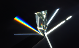
An optical prism is a transparent optical element with flat, polished surfaces that are designed to refract light. At least one surface must be angled — elements with two parallel surfaces are not prisms. The most familiar type of optical prism is the triangular prism, which has a triangular base and rectangular sides. Not all optical prisms are geometric prisms, and not all geometric prisms would count as an optical prism. Prisms can be made from any material that is transparent to the wavelengths for which they are designed. Typical materials include glass, acrylic and fluorite.

Optics is the branch of physics which involves the behavior and properties of light, including its interactions with matter and the construction of instruments that use or detect it. Optics usually describes the behavior of visible, ultraviolet, and infrared light. Because light is an electromagnetic wave, other forms of electromagnetic radiation such as X-rays, microwaves, and radio waves exhibit similar properties.

<span class="mw-page-title-main">Diffraction-limited system</span> Optical system with resolution performance at the instruments theoretical limit

In optics, any optical instrument or system – a microscope, telescope, or camera – has a principal limit to its resolution due to the physics of diffraction. An optical instrument is said to be diffraction-limited if it has reached this limit of resolution performance. Other factors may affect an optical system's performance, such as lens imperfections or aberrations, but these are caused by errors in the manufacture or calculation of a lens, whereas the diffraction limit is the maximum resolution possible for a theoretically perfect, or ideal, optical system.

In many areas of science, Bragg's law, Wulff–Bragg's condition, or Laue–Bragg interference are a special case of Laue diffraction, giving the angles for coherent scattering of waves from a large crystal lattice. It describes how the superposition of wave fronts scattered by lattice planes leads to a strict relation between the wavelength and scattering angle. This law was initially formulated for X-rays, but it also applies to all types of matter waves including neutron and electron waves if there are a large number of atoms, as well as visible light with artificial periodic microscale lattices.

<span class="mw-page-title-main">Reflection (physics)</span> "Bouncing back" of waves at an interface

Reflection is the change in direction of a wavefront at an interface between two different media so that the wavefront returns into the medium from which it originated. Common examples include the reflection of light, sound and water waves. The law of reflection says that for specular reflection the angle at which the wave is incident on the surface equals the angle at which it is reflected.

<span class="mw-page-title-main">Optical coating</span> Material which alters light reflection or transmission on optics

An optical coating is one or more thin layers of material deposited on an optical component such as a lens, prism or mirror, which alters the way in which the optic reflects and transmits light. These coatings have become a key technology in the field of optics. One type of optical coating is an anti-reflective coating, which reduces unwanted reflections from surfaces, and is commonly used on spectacle and camera lenses. Another type is the high-reflector coating, which can be used to produce mirrors that reflect greater than 99.99% of the light that falls on them. More complex optical coatings exhibit high reflection over some range of wavelengths, and anti-reflection over another range, allowing the production of dichroic thin-film filters.

<span class="mw-page-title-main">Specular reflection</span> Mirror-like wave reflection

Specular reflection, or regular reflection, is the mirror-like reflection of waves, such as light, from a surface.

<span class="mw-page-title-main">Backscatter</span> Reflection which reverses the direction of a wave, particle, or signal

In physics, backscatter is the reflection of waves, particles, or signals back to the direction from which they came. It is usually a diffuse reflection due to scattering, as opposed to specular reflection as from a mirror, although specular backscattering can occur at normal incidence with a surface. Backscattering has important applications in astronomy, photography, and medical ultrasonography. The opposite effect is forward scatter, e.g. when a translucent material like a cloud diffuses sunlight, giving soft light.

<span class="mw-page-title-main">Zone plate</span> Device used to focus light using diffraction

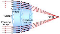
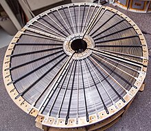
A zone plate is a device used to focus light or other things exhibiting wave character. Unlike lenses or curved mirrors, zone plates use diffraction instead of refraction or reflection. Based on analysis by French physicist Augustin-Jean Fresnel, they are sometimes called Fresnel zone plates in his honor. The zone plate's focusing ability is an extension of the Arago spot phenomenon caused by diffraction from an opaque disc.

<span class="mw-page-title-main">X-ray spectroscopy</span> Technique to characterize materials using X-ray radiation

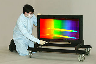
X-ray spectroscopy is a general term for several spectroscopic techniques for characterization of materials by using x-ray radiation.

<span class="mw-page-title-main">Anti-reflective coating</span> Optical coating that reduces reflection

An antireflective, antiglare or anti-reflection (AR) coating is a type of optical coating applied to the surface of lenses, other optical elements, and photovoltaic cells to reduce reflection. In typical imaging systems, this improves the efficiency since less light is lost due to reflection. In complex systems such as cameras, binoculars, telescopes, and microscopes the reduction in reflections also improves the contrast of the image by elimination of stray light. This is especially important in planetary astronomy. In other applications, the primary benefit is the elimination of the reflection itself, such as a coating on eyeglass lenses that makes the eyes of the wearer more visible to others, or a coating to reduce the glint from a covert viewer's binoculars or telescopic sight.

<span class="mw-page-title-main">Acousto-optic modulator</span> Device which diffracts light via sound waves

An acousto-optic modulator (AOM), also called a Bragg cell or an acousto-optic deflector (AOD), uses the acousto-optic effect to diffract and shift the frequency of light using sound waves. They are used in lasers for Q-switching, telecommunications for signal modulation, and in spectroscopy for frequency control. A piezoelectric transducer is attached to a material such as glass. An oscillating electric signal drives the transducer to vibrate, which creates sound waves in the material. These can be thought of as moving periodic planes of expansion and compression that change the index of refraction. Incoming light scatters off the resulting periodic index modulation and interference occurs similar to Bragg diffraction. The interaction can be thought of as a three-wave mixing process resulting in sum-frequency generation or difference-frequency generation between phonons and photons.

<span class="mw-page-title-main">Distributed Bragg reflector</span> Structure used in waveguides

A distributed Bragg reflector (DBR) is a reflector used in waveguides, such as optical fibers. It is a structure formed from multiple layers of alternating materials with different refractive index, or by periodic variation of some characteristic of a dielectric waveguide, resulting in periodic variation in the effective refractive index in the guide. Each layer boundary causes a partial reflection and refraction of an optical wave. For waves whose vacuum wavelength is close to four times the optical thickness of the layers, the interaction between these beams generates constructive interference, and the layers act as a high-quality reflector. The range of wavelengths that are reflected is called the photonic stopband. Within this range of wavelengths, light is "forbidden" to propagate in the structure.

<span class="mw-page-title-main">Acousto-optics</span> The study of sound and light interaction

Acousto-optics is a branch of physics that studies the interactions between sound waves and light waves, especially the diffraction of laser light by ultrasound through an ultrasonic grating.

A holographic optical element (HOE) is an optical component (mirror, lens, directional diffuser, etc.) that produces holographic images using principles of diffraction. HOE is most commonly used in transparent displays, 3D imaging, and certain scanning technologies.

References

  1. 1 2 Spiller, E. (2015). "X-Rays: Optical Elements". In Craig Hoffman; Ronald Driggers (eds.). Encyclopedia of Optical Engineering (2nd ed.). Taylor & Francis. doi:10.1081/E-EOE2. ISBN   978-1-351-24718-4.
  2. MacDonald, Carolyn A. (2010). "Focusing Polycapillary Optics and Their Applications". X-Ray Optics and Instrumentation. 2010: 1–17. Bibcode:2010XROI.2010E..11M. doi: 10.1155/2010/867049 .
  3. "Polycapillary Focusing Optics – X-Ray". XOS. Retrieved 2016-12-13.
  4. "Zone Plates". X-Ray Data Booklet. Center for X-ray Optics and Advanced Light Source. Lawrence Berkeley National Laboratory. Retrieved 13 January 2015.
  5. Snigirev, A. (1998). "Focusing high-energy x rays by compound refractive lenses". Applied Optics. 37 (4): 653–662. Bibcode:1998ApOpt..37..653S. doi:10.1364/AO.37.000653. PMID   18268637.
  6. "Compound refractive X-ray optics (CRLs)". X-ray-Optics.de. Retrieved 2016-12-14.
  7. 1 2 Rob Petre. "X-ray Imaging Systems". NASA.
  8. Bradt, Hale (2007). Astronomy Methods. Cambridge, UK: Cambridge University Press. p. 106. ISBN   978-0-521-53551-9.
  9. Wolter, H. (1952). "Glancing Incidence Mirror Systems as Imaging Optics for X-rays". Annalen der Physik. 10 (1): 94. Bibcode:1952AnP...445...94W. doi:10.1002/andp.19524450108.
  10. Wolter, H. (1952). "Verallgemeinerte Schwarzschildsche Spiegelsysteme streifender Reflexion als Optiken für Röntgenstrahlen". Annalen der Physik. 10 (4–5): 286–295. Bibcode:1952AnP...445..286W. doi:10.1002/andp.19524450410.
  11. Pikuz, T. A.; Faenov, A. Ya.; Fraenkel, M.; Zigler, A.; Flora, F.; Bollanti, S.; Di Lazzaro, P.; Letardi, T.; Grilli, A.; Palladino, L.; Tomassetti, G.; Reale, A.; Reale, L.; Scafati, A.; Limongi, T.; Bonfigli, F.; Alainelli, L.; Sanchez del Rio, M. (2000). Using spherically bent crystals for obtaining high-resolution, large-field, monochromatic X-ray backlighting imaging for wide range of Bragg angles. 27th IEEE International Conference on Plasma Science. p. 183. doi:10.1109/PLASMA.2000.854969.
  12. Kumakhov, M. A. (1990). "Channeling of photons and new X-ray optics". Nuclear Instruments and Methods in Physics Research Section B. 48 (1–4): 283–286. Bibcode:1990NIMPB..48..283K. doi:10.1016/0168-583X(90)90123-C.
  13. Dabagov, SB (2003). "Channeling of neutral particles in micro- and nanocapillaries". Physics-Uspekhi. 46 (10): 1053–1075. Bibcode:2003PhyU...46.1053D. doi:10.1070/PU2003v046n10ABEH001639. S2CID   115277219.
  14. An introduction to X-Ray Optics.
  15. Polycapillary Optics Archived 2013-12-04 at the Wayback Machine .
  16. Fredenberg, Erik; Cederström, Björn; Åslund, Magnus; Nillius, Peter; Danielsson, Mats (27 January 2009). "An efficient pre-object collimator based on an x-ray lens". Medical Physics. 36 (2): 626–633. arXiv: 2101.07788 . Bibcode:2009MedPh..36..626F. doi:10.1118/1.3062926. PMID   19292003. S2CID   44470446.
  17. Fredenberg, Erik; Cederström, Björn; Nillius, Peter; Ribbing, Carolina; Karlsson, Staffan; Danielsson, Mats (2009). "A low-absorption x-ray energy filter for small-scale applications". Optics Express. 17 (14): 11388–11398. Bibcode:2009OExpr..1711388F. doi: 10.1364/OE.17.011388 . PMID   19582053.
  18. "CXRO X-Ray interactions with matter". henke.lbl.gov. Retrieved 2016-02-19.
  19. 1 2 NuStar: Instrumentation: Optics. Archived 1 November 2010 at the Wayback Machine