
The 25-pair color code, originally known as even-count color code, [1] is a color code used to identify individual conductors in twisted-pair wiring for telecommunications.
The 25-pair color code, originally known as even-count color code, [1] is a color code used to identify individual conductors in twisted-pair wiring for telecommunications.
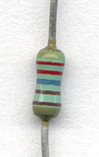
With the development of new generations of telecommunication cables with polyethylene-insulated conductors (PIC) by Bell Laboratories for the Bell System in the 1950s, new methods were developed to mark each individual conductor in cables. [2] Each wire is identified by the combination of two colors, one of which is the major color, and the second the minor color. Major and minor colors are chosen from two different groups of five, resulting in 25 color combinations. The color combinations are applied to the insulation that covers each conductor. Typically, one color is a prominent background color of the insulation, and the other is a tracer, consisting of stripes, rings, or dots, applied over the background. The background color always matches the tracer color of its paired conductor, and vice versa.
The major, or primary group of colors consists of the sequence of white, red, black, yellow, and violet (mnemonic: Why run backwards? You'll vomit!). [3] [ ISBN missing ] The minor, or secondary color is chosen from the sequence blue, orange, green, brown, and slate (mnemonic: Bell operators give better service. [4] ). [5] [6] [7]

| Pair no. | Major color | Minor color | ||
|---|---|---|---|---|
| 1 | White | Blue | ||
| 2 | Orange | |||
| 3 | Green | |||
| 4 | Brown | |||
| 5 | Slate | |||
| 6 | Red | Blue | ||
| 7 | Orange | |||
| 8 | Green | |||
| 9 | Brown | |||
| 10 | Slate | |||
| 11 | Black | Blue | ||
| 12 | Orange | |||
| 13 | Green | |||
| 14 | Brown | |||
| 15 | Slate | |||
| 16 | Yellow | Blue | ||
| 17 | Orange | |||
| 18 | Green | |||
| 19 | Brown | |||
| 20 | Slate | |||
| 21 | Violet | Blue | ||
| 22 | Orange | |||
| 23 | Green | |||
| 24 | Brown | |||
| 25 | Slate | |||
The wire pairs are referenced directly by their color combination, or by the pair number. For example, pair 9 is also called the red-brown pair. In technical tabulations, the colors are often suitably abbreviated.
Violet is the standard name in the telecommunications and electronics industry, but it is sometimes referred to as purple. Similarly, slate is a particular shade of gray. The names of most of the colors were taken from the conventional colors of the rainbow or optical spectrum, and in the electronic color code, which uses the same ten colors, albeit in a different order.[ citation needed ]
When used for plain old telephone service (POTS), the first wire is known as the tip or A-leg (U.K.) conductor, and is usually connected to the positive side of a direct current (DC) circuit, while the second wire is known as the ring lead or B-leg (U.K.), and is connected to the negative side of the circuit. Neither of these two sides of the line has a connection to the local ground. This creates a balanced audio circuit with common-mode rejection, also known as a differential pair. The tip and ring convention is based on the 1⁄4 inch (6.35 mm) TRS phone connectors, which were employed in telephone switchboards in the 19th and 20th centuries, where the tip contact of the connector is separated from the ring contact by a spacer of insulation. The connection furthest from the cable is known as the tip, the middle connection is the ring, and the (largest) connection closest to the wire is the sleeve.
Small cables with 5 pairs or less sometimes omit the white tracer color from the ring wires, as it is not needed. Large cables would usually omit both tracer colors requiring both wires in a twisted pair to be examined to identify the pair, [8] but as manufacturing techniques have improved this no longer offers a cost saving and so is rarely seen.[ citation needed ]
Older Bell System wiring inside customer premises used untwisted wire cable, with each conductor a different solid color. 4-conductor was most common, but 6-conductor was sometimes used and the colors for up to 5 pairs (10 conductors) were defined. They correspond to the current 25-color code as follows:
| Tip | Pair | Ring | ||
|---|---|---|---|---|
| Old color | New colors | Old Color | New Colors | |
| | | Line 1 | | |
| | | Line 2 | | |
| | | Line 3 | | |
| | | Line 4 | | |
| pink | | Line 5 | | |
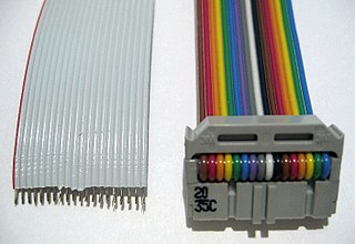
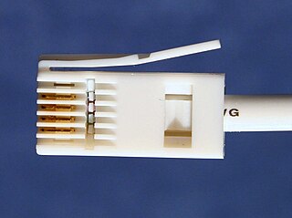
A common application of the 25-pair color code is the cabling for the Registered Jack interface RJ21, which uses a female 50-pin miniature ribbon connector, as shown in the following table. The geometry of the pins of the receptacle (right hand image) corresponds to the pin numbers of the table. The left column of pins are the ring (R) conductors, while all tip (T) conductors are on the right.
| Color (minor/major) | (R) | (T) | Color (major/minor) | The corresponding pin order in the female RJ21 connector | |
|---|---|---|---|---|---|
| Pin no. | |||||
| | 1 | 26 | |  | |
| | 2 | 27 | | ||
| | 3 | 28 | | ||
| | 4 | 29 | | ||
| | 5 | 30 | | ||
| | 6 | 31 | | ||
| | 7 | 32 | | ||
| | 8 | 33 | | ||
| | 9 | 34 | | ||
| | 10 | 35 | | ||
| | 11 | 36 | | ||
| | 12 | 37 | | ||
| | 13 | 38 | | ||
| | 14 | 39 | | ||
| | 15 | 40 | | ||
| | 16 | 41 | | ||
| | 17 | 42 | | ||
| | 18 | 43 | | ||
| | 19 | 44 | | ||
| | 20 | 45 | | ||
| | 21 | 46 | | ||
| | 22 | 47 | | ||
| | 23 | 48 | | ||
| | 24 | 49 | | ||
| | 25 | 50 | | ||
For cables with more than 25 pairs, each group of 25 is called a binder group. The binder groups are marked with mylar ribbons using the same color coding system, starting with a white/blue ribbon, then a white/orange ribbon, and so on. The 24th binder group has a violet/brown ribbon, completing a super binder of 600 pairs. [5] [6]
In cables of more than 600 pairs, each of the 600-pair super binder group bundles is wrapped with a mylar binder ribbon, or string, matching the "tip" colors of the color code, starting with white. The pattern then starts over with the first 25-pair group as white/blue, and continues indefinitely, in multiples of 600 pairs or parts thereof. For example, a 900-pair cable has the first 600 pairs in 24 groups of 25 pairs in a white binder, and the remaining 300 pairs in 12 groups of 25 pairs wrapped in a red binder. [5] [6]
Some cables are "mirrored" or "clocked" with a pattern that is known throughout the telephone industry. Starting with the first binder group in the center, the technician counts the cable's groups in a spiral direction depending on the location of the central office or switch. If looking at the cable's core and the switch is in that direction, the groups are counted counter-clockwise. If the cable is the field side, the count is clockwise. There are indicators on the mylar ribbons to know where to begin for each layer and a diagram for the different cable sizes should be readily available for reference. [5] [6]
Other color schemes are sometimes used for outdoor cables, particularly outside the U.S., but this color code is common for aerial and underground cables up to several thousand pairs in North America. In the UK, the British Post Office (later BT) used this color code for what is now known loosely as CW1308 specification cables, referring to the Post Office's "Cable and Wire" specification No. 1308.

When working on aerial cable splicing and installation, it is common to use a telephone lineman's set or "butt set" to communicate over long distances. To facilitate this, extra pairs of wires are embedded in cables using "major" colors for both wires (instead of the major/minor color combinations used for the rest). One extra pair (red–white) may be embedded into cables that are 6 to 75 pairs; two pairs (red–white and black–white) may be encapsulated in cables of 100 to 300 pairs; and three pairs (red–white, black–white, and yellow–white) may be included in cables of 400 to 900 pairs. [6] These extra pairs are often referred to as "talk pairs", and are never used for subscriber service.
A color coding method used for fiber-optic cables, TIA-598-C, starts with the same first ten colors, adding the color rose for 11, and aqua for 12. [10]

An electrical insulator is a material in which electric current does not flow freely. The atoms of the insulator have tightly bound electrons which cannot readily move. Other materials—semiconductors and conductors—conduct electric current more easily. The property that distinguishes an insulator is its resistivity; insulators have higher resistivity than semiconductors or conductors. The most common examples are non-metals.

A 600 series connector is an obsolete three-pin connector with up to six conductors.
An electronic color code or electronic colour code is used to indicate the values or ratings of electronic components, usually for resistors, but also for capacitors, inductors, diodes and others. A separate code, the 25-pair color code, is used to identify wires in some telecommunications cables. Different codes are used for wire leads on devices such as transformers or in building wiring.

Twisted pair cabling is a type of communications cable in which two conductors of a single circuit are twisted together for the purposes of improving electromagnetic compatibility. Compared to a single conductor or an untwisted balanced pair, a twisted pair reduces electromagnetic radiation from the pair and crosstalk between neighbouring pairs and improves rejection of external electromagnetic interference. It was invented by Alexander Graham Bell.

Components of an electrical circuit are electrically connected if an electric current can run between them through an electrical conductor. An electrical connector is an electromechanical device used to create an electrical connection between parts of an electrical circuit, or between different electrical circuits, thereby joining them into a larger circuit.
A ribbon cable is a cable with many conducting wires running parallel to each other on the same flat plane. As a result, the cable is wide and flat. Its name comes from its resemblance to a piece of ribbon.

A registered jack (RJ) is a standardized telecommunication network interface for connecting voice and data equipment to a computer service provided by a local exchange carrier or long distance carrier. Registered interfaces were first defined in the Universal Service Ordering Code (USOC) system of the Bell System in the United States for complying with the registration program for customer-supplied telephone equipment mandated by the Federal Communications Commission (FCC) in the 1970s. Subsequently, in 1980 they were codified in title 47 of the Code of Federal Regulations Part 68. Registered jack connections began to see use after their invention in 1973 by Bell Labs. The specification includes physical construction, wiring, and signal semantics. Accordingly, registered jacks are primarily named by the letters RJ, followed by two digits that express the type. Additional letter suffixes indicate minor variations. For example, RJ11, RJ14, and RJ25 are the most commonly used interfaces for telephone connections for one-, two-, and three-line service, respectively. Although these standards are legal definitions in the United States, some interfaces are used worldwide.

An audio multicore cable is a thick cable which usually contains 4–64 individual audio cables inside a common, sturdy outer jacket. Audio multicore cables are used to convey many audio signals between two locations, such as in audio recording, sound reinforcement, PA systems and broadcasting. Multicores often route many signals from microphones or musical instruments to a mixing console, and can also carry signals from a mixing console back to speakers.
Electrical wiring in North America follows the regulations and standards applicable at the installation location. It is also designed to provide proper function, and is also influenced by history and traditions of the location installation.

A telephone jack and a telephone plug are electrical connectors for connecting a telephone set or other telecommunications apparatus to the telephone wiring inside a building, establishing a connection to a telephone network. The plug is inserted into its counterpart, the jack, which is commonly affixed to a wall or baseboard. The standards for telephone jacks and plugs vary from country to country, though the 6P2C style modular plug has become by far the most common type.

A banana connector is a single-wire electrical connector used for joining wires to equipment. The term 4 mm connector is also used, especially in Europe, although not all banana connectors will mate with 4 mm parts, and 2 mm banana connectors exist. Various styles of banana plug contacts exist, all based on the concept of spring metal applying outward force into the unsprung cylindrical jack to produce a snug fit with good electrical conductivity. Common types include: a solid pin split lengthwise and splayed slightly, a tip of four leaf springs, a cylinder with a single leaf spring on one side, a bundle of stiff wire, a central pin surrounded by a multiple-slit cylinder with a central bulge, or simple sheet spring metal rolled into a nearly complete cylinder. The plugs are frequently used to terminate patch cords for electronic test equipment such as laboratory power supply units, while sheathed banana plugs are common on multimeter probe leads.

A telephone line or telephone circuit is a single-user circuit on a telephone communication system. It is designed to reproduce speech of a quality that is understandable. It is the physical wire or other signaling medium connecting the user's telephone apparatus to the telecommunications network, and usually also implies a single telephone number for billing purposes reserved for that user.
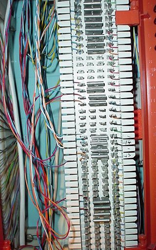
A 66 block is a type of punch-down block used to connect sets of wires in a telephone system. They have been manufactured in four common configurations, A, B, E and M. A and B styles have the clip rows on 0.25" centers while E and M have the clip rows on 0.20" centers. The A blocks have 25 slotted holes on the left side for position the incoming building cable with a 50 slot fanning strip on the right side for distribution cables. They have been obsolete for many years. The B & M styles have 50 slot fanning strip on both sides. The B style is used mainly in distribution panels where several destinations need to connect to the same source. The M blocks are often used to connect a single instrument to such a distribution block. The E style has 5 columns of 10 2 clips rows and are used for transitioning from the 25 pair distribution cable to a 25 pair RJ21 style female ribbon connector.
The micro ribbon or miniature ribbonconnector is a common type of electrical connector for a variety of applications, such as in computer and telecommunications equipment having many contacts.
An insulation-displacement contact (IDC), also known as insulation-piercing contact (IPC), is an electrical connector designed to be connected to the conductor(s) of an insulated cable by a connection process which forces a selectively sharpened blade or blades through the insulation, bypassing the need to strip the conductors of insulation before connecting. When properly made, the connector blade cold-welds to the conductor, making a theoretically reliable gas-tight connection.

A computer port is a hardware piece on a computer where an electrical connector can be plugged to link the device to external devices, such as another computer, a peripheral device or network equipment.This is a non-standard term.
A modular connector is a type of electrical connector for cords and cables of electronic devices and appliances, such as in computer networking, telecommunication equipment, and audio headsets.

Tip and ring are the two conductors or sides of a telephone line. Their names are derived from the telephone plugs used for connecting telephone calls in manual switchboards. One side of the line is connected to the metal tip of the plug, and the second is connected to a metal ring behind the tip, separated and insulated from the tip by a non-conducting material. When inserted into a jack, the plug's tip conductor connects first, followed by the ring conductor. In many European countries, tip and ring are referred to as the A and B wires.
British telephone sockets were introduced in their current plug and socket form on 19 November 1981 by British Telecom to allow subscribers to connect their own telephones. The connectors are specified in British Standard BS 6312. Electrical characteristics of the telephone interface are specified by individual network operators, e.g. in British Telecom's SIN 351. Electrical characteristics required of British telephones used to be specified in BS 6305.
ANSI/TIA-568 is a technical standard for commercial building cabling for telecommunications products and services. The title of the standard is Commercial Building Telecommunications Cabling Standard and is published by the Telecommunications Industry Association (TIA), a body accredited by the American National Standards Institute (ANSI).