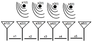
A sensor array is a group of sensors, usually deployed in a certain geometry pattern, used for collecting and processing electromagnetic or acoustic signals. The advantage of using a sensor array over using a single sensor lies in the fact that an array adds new dimensions to the observation, helping to estimate more parameters and improve the estimation performance. For example an array of radio antenna elements used for beamforming can increase antenna gain in the direction of the signal while decreasing the gain in other directions, i.e., increasing signal-to-noise ratio (SNR) by amplifying the signal coherently. Another example of sensor array application is to estimate the direction of arrival of impinging electromagnetic waves. The related processing method is called array signal processing. Application examples of array signal processing include radar/sonar, wireless communications, seismology, machine condition monitoring, astronomical observations fault diagnosis, etc.

Array processing is a wide area of research in the field of signal processing that extends from the simplest form of 1 dimensional line arrays to 2 and 3 dimensional array geometries. Array structure can be defined as a set of sensors that are spatially separated, e.g. radio antenna and seimic arrays. The sensors used for a specific problem may vary widely, for example microphones, accelerometers and telescopes. However, many similarities exist, the most fundamental of which may be an assumption of wave propagation. Wave propagation means there is a systemic relationship between the signal received on spatially separated sensors. By creating a physical model of the wave propagation, or in machine learning applications a training data set, the relationships between the signals received on spatially separated sensors can be leveraged for many applications.
Smart antennas are antenna arrays with smart signal processing algorithms used to identify spatial signal signatures such as the direction of arrival (DOA) of the signal, and use them to calculate beamforming vectors which are used to track and locate the antenna beam on the mobile/target. Smart antennas should not be confused with reconfigurable antennas, which have similar capabilities but are single element antennas and not antenna arrays.

Antenna diversity, also known as space diversity or spatial diversity, is any one of several wireless diversity schemes that uses two or more antennas to improve the quality and reliability of a wireless link. Often, especially in urban and indoor environments, there is no clear line-of-sight (LOS) between transmitter and receiver. Instead the signal is reflected along multiple paths before finally being received. Each of these bounces can introduce phase shifts, time delays, attenuations, and distortions that can destructively interfere with one another at the aperture of the receiving antenna.

Space-time adaptive processing (STAP) is a signal processing technique most commonly used in radar systems. It involves adaptive array processing algorithms to aid in target detection. Radar signal processing benefits from STAP in areas where interference is a problem. Through careful application of STAP, it is possible to achieve order-of-magnitude sensitivity improvements in target detection.
Radio resource management (RRM) is the system level management of co-channel interference, radio resources, and other radio transmission characteristics in wireless communication systems, for example cellular networks, wireless local area networks, wireless sensor systems radio broadcasting networks. RRM involves strategies and algorithms for controlling parameters such as transmit power, user allocation, beamforming, data rates, handover criteria, modulation scheme, error coding scheme, etc. The objective is to utilize the limited radio-frequency spectrum resources and radio network infrastructure as efficiently as possible.
Precoding is a generalization of beamforming to support multi-stream transmission in multi-antenna wireless communications. In conventional single-stream beamforming, the same signal is emitted from each of the transmit antennas with appropriate weighting such that the signal power is maximized at the receiver output. When the receiver has multiple antennas, single-stream beamforming cannot simultaneously maximize the signal level at all of the receive antennas. In order to maximize the throughput in multiple receive antenna systems, multi-stream transmission is generally required.
Multi-user MIMO (MU-MIMO) is a set of multiple-input and multiple-output (MIMO) technologies for wireless communication, in which a set of users or wireless terminals, each with one or more antennas, communicate with each other. In contrast, single-user MIMO considers a single multi-antenna transmitter communicating with a single multi-antenna receiver. In a similar way that OFDMA adds multiple access (multi-user) capabilities to OFDM, MU-MIMO adds multiple access (multi-user) capabilities to MIMO. MU-MIMO has been investigated since the beginning of research into multi-antenna communication.
In radio, Cooperative multiple-input multiple-output is an advanced technology that can effectively exploit the spatial domain of mobile fading channels to bring significant performance improvements to wireless communication systems. It is also called Network MIMO, Distributed MIMO, Virtual MIMO, and Virtual Antenna Arrays.

WiMAX MIMO refers to the use of Multiple-input multiple-output communications (MIMO) technology on WiMAX, which is the technology brand name for the implementation of the standard IEEE 802.16.

In radio, multiple-input and multiple-output, or MIMO, is a method for multiplying the capacity of a radio link using multiple transmission and receiving antennas to exploit multipath propagation. MIMO has become an essential element of wireless communication standards including IEEE 802.11n (Wi-Fi), IEEE 802.11ac (Wi-Fi), HSPA+ (3G), WiMAX (4G), and Long Term Evolution. More recently, MIMO has been applied to power-line communication for 3-wire installations as part of ITU G.hn standard and HomePlug AV2 specification.
3G MIMO describes MIMO techniques which have been considered as 3G standard techniques.
Many antennas is a smart antenna technique which overcomes the performance limitation of single user multiple-input multiple-output (MIMO) techniques. In cellular communication, the maximum number of considered antennas for downlink is 2 and 4 to support 3GPP Long Term Evolution (LTE) and IMT Advanced requirements, respectively. Since the available spectrum band will probably be limited while the data rate requirement will continuously increase beyond IMT-A to support the mobile multimedia services, it is highly probable that the number of transmit antennas at the base station must be increased to 8–64 or more. The installation of many antennas at single base stations introduced many challenges and required development of several high technologies: a new SDMA engine, a new beamforming algorithm and a new antenna array.

WSDMA is a high bandwidth channel access method, developed for multi-transceiver systems such as active array antennas. WSDMA is a beamforming technique suitable for overlay on the latest air-interface protocols including WCDMA and OFDM. WSDMA enabled systems can determine the angle of arrival (AoA) of received signals to spatially divide a cell sector into many sub-sectors. This spatial awareness provides information necessary to maximise Carrier to Noise+Interference Ratio (CNIR) link budget, through a range of digital processing routines. WSDMA facilitates a flexible approach to how uplink and downlink beamforming is performed and is capable of spatial filtering known interference generating locations.
The first smart antennas were developed for military communications and intelligence gathering. The growth of cellular telephone in the 1980s attracted interest in commercial applications. The upgrade to digital radio technology in the mobile phone, indoor wireless network, and satellite broadcasting industries created new opportunities for smart antennas in the 1990s, culminating in the development of the MIMO technology used in 4G wireless networks.

Gregory “Greg” Raleigh, is an American radio scientist, inventor, and entrepreneur who has made contributions in the fields of wireless communication, information theory, mobile operating systems, medical devices, and network virtualization. His discoveries and inventions include the first wireless communication channel model to accurately predict the performance of advanced antenna systems, the MIMO-OFDM technology used in contemporary Wi-Fi and 4G wireless networks and devices, higher accuracy radiation beam therapy for cancer treatment, improved 3D surgery imaging, and a cloud-based Network Functions Virtualization platform for mobile network operators that enables users to customize and modify their smartphone services.
Multiple-input, multiple-output orthogonal frequency-division multiplexing (MIMO-OFDM) is the dominant air interface for 4G and 5G broadband wireless communications. It combines multiple-input, multiple-output (MIMO) technology, which multiplies capacity by transmitting different signals over multiple antennas, and orthogonal frequency-division multiplexing (OFDM), which divides a radio channel into a large number of closely spaced subchannels to provide more reliable communications at high speeds. Research conducted during the mid-1990s showed that while MIMO can be used with other popular air interfaces such as time-division multiple access (TDMA) and code-division multiple access (CDMA), the combination of MIMO and OFDM is most practical at higher data rates.
Per-user unitary rate control (PU2RC) is a multi-user MIMO (multiple-input and multiple-output) scheme. PU2RC uses both transmission pre-coding and multi-user scheduling. By doing that, the network capacity is further enhanced than the capacity of the single-user MIMO scheme.

Multiple-input multiple-output (MIMO) radar is an advanced type of phased array radar employing digital receivers and waveform generators distributed across the aperture. MIMO radar signals propagate in a fashion similar to Multistatic radar. However, instead of distributing the radar elements throughout the surveillance area, antennas are closely located to obtain better spatial resolution, Doppler resolution, and dynamic range. MIMO radar may also be used to obtain Low-probability-of-intercept radar properties.


