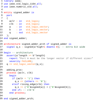
The VHSIC Hardware Description Language (VHDL) is a hardware description language (HDL) that can model the behavior and structure of digital systems at multiple levels of abstraction, ranging from the system level down to that of logic gates, for design entry, documentation, and verification purposes. Since 1987, VHDL has been standardized by the Institute of Electrical and Electronics Engineers (IEEE) as IEEE Std 1076; the latest version of which is IEEE Std 1076-2019. To model analog and mixed-signal systems, an IEEE-standardized HDL based on VHDL called VHDL-AMS has been developed.
Verilog, standardized as IEEE 1364, is a hardware description language (HDL) used to model electronic systems. It is most commonly used in the design and verification of digital circuits at the register-transfer level of abstraction. It is also used in the verification of analog circuits and mixed-signal circuits, as well as in the design of genetic circuits. In 2009, the Verilog standard was merged into the SystemVerilog standard, creating IEEE Standard 1800-2009. Since then, Verilog is officially part of the SystemVerilog language. The current version is IEEE standard 1800-2017.
In computer engineering, a hardware description language (HDL) is a specialized computer language used to describe the structure and behavior of electronic circuits, and most commonly, digital logic circuits.
Electronic design automation (EDA), also referred to as electronic computer-aided design (ECAD), is a category of software tools for designing electronic systems such as integrated circuits and printed circuit boards. The tools work together in a design flow that chip designers use to design and analyze entire semiconductor chips. Since a modern semiconductor chip can have billions of components, EDA tools are essential for their design; this article in particular describes EDA specifically with respect to integrated circuits (ICs).

Accellera Systems Initiative (Accellera) is a standards organization that supports a mix of user and vendor standards and open interfaces development in the area of electronic design automation (EDA) and integrated circuit (IC) design and manufacturing. It is less constrained than the Institute of Electrical and Electronics Engineers (IEEE) and is therefore the starting place for many standards. Once mature and adopted by the broader community, the standards are usually transferred to the IEEE.
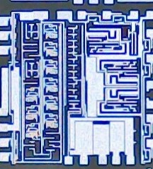
A mixed-signal integrated circuit is any integrated circuit that has both analog circuits and digital circuits on a single semiconductor die. Their usage has grown dramatically with the increased use of cell phones, telecommunications, portable electronics, and automobiles with electronics and digital sensors.
In electronic design, a semiconductor intellectual property core, IP core, or IP block is a reusable unit of logic, cell, or integrated circuit layout design that is the intellectual property of one party. IP cores can be licensed to another party or owned and used by a single party. The term comes from the licensing of the patent or source code copyright that exists in the design. Designers of application-specific integrated circuits (ASIC) and systems of field-programmable gate array (FPGA) logic can use IP cores as building blocks.
Specman is an EDA tool that provides advanced automated functional verification of hardware designs. It provides an environment for working with, compiling, and debugging testbench environments written in the e Hardware Verification Language. Specman also offers automated testbench generation to boost productivity in the context of block, chip, and system verification.

Integrated circuit design, or IC design, is a sub-field of electronics engineering, encompassing the particular logic and circuit design techniques required to design integrated circuits, or ICs. ICs consist of miniaturized electronic components built into an electrical network on a monolithic semiconductor substrate by photolithography.

Quite Universal Circuit Simulator (Qucs) is a free-software electronics circuit simulator software application released under GPL. It offers the ability to set up a circuit with a graphical user interface and simulate the large-signal, small-signal and noise behaviour of the circuit. Pure digital simulations are also supported using VHDL and/or Verilog.
Verilog-AMS is a derivative of the Verilog hardware description language that includes analog and mixed-signal extensions (AMS) in order to define the behavior of analog and mixed-signal systems. It extends the event-based simulator loops of Verilog/SystemVerilog/VHDL, by a continuous-time simulator, which solves the differential equations in analog-domain. Both domains are coupled: analog events can trigger digital actions and vice versa.
Verilog-A is an industry standard modeling language for analog circuits. It is the continuous-time subset of Verilog-AMS. A few commercial applications may export MEMS designs in Verilog-A format.
e is a hardware verification language (HVL) which is tailored to implementing highly flexible and reusable verification testbenches.

Electronic circuit simulation uses mathematical models to replicate the behavior of an actual electronic device or circuit. Simulation software allows for modeling of circuit operation and is an invaluable analysis tool. Due to its highly accurate modeling capability, many colleges and universities use this type of software for the teaching of electronics technician and electronics engineering programs. Electronics simulation software engages its users by integrating them into the learning experience. These kinds of interactions actively engage learners to analyze, synthesize, organize, and evaluate content and result in learners constructing their own knowledge.
Aldec, Inc. is a privately owned electronic design automation company based in Henderson, Nevada that provides software and hardware used in creation and verification of digital designs targeting FPGA and ASIC technologies.
The Design Automation Standards Committee (DASC) is a subgroup of interested individuals members of the Institute of Electrical and Electronics Engineers (IEEE) Computer Society and Standards Association. It oversees IEEE Standards that are related to computer-aided design. It is part of the IEEE Computer Society.
VHDL-AMS is a derivative of the hardware description language VHDL. It includes analog and mixed-signal extensions (AMS) in order to define the behavior of analog and mixed-signal systems.
Intelligent Verification, including intelligent testbench automation, is a form of functional verification of electronic hardware designs used to verify that a design conforms to specification before device fabrication. Intelligent verification uses information derived from the design and specification(s) to expose bugs in and between hardware IPs. Intelligent verification tools require considerably less engineering effort and user guidance to achieve verification results that meet or exceed the standard approach of writing a testbench program.
This page is a comparison of electronic design automation (EDA) software which is used today to design the near totality of electronic devices. Modern electronic devices are too complex to be designed without the help of a computer. Electronic devices may consist of integrated circuits (ICs), printed circuit boards (PCBs), field programmable gate arrays (FPGAs) or a combination of them. Integrated circuits may consist of a combination of digital and analog circuits. These circuits can contain a combination of transistors, resistors, capacitors or specialized components such as analog neural networks, antennas or fuses.
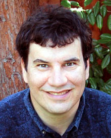
Kenneth S. Kundert is an engineer that is notable for his work in the area of Electronic Design Automation (EDA). He studied electrical engineering at the University of California, Berkeley under professors Alberto Sangiovanni-Vincentelli and Robert G. Meyer and received his doctorate in 1989. During this time, he created the circuit simulator that eventually became the Advanced Design System from what is now PathWave Design and the Spectre circuit simulator from Cadence Design Systems.